
Service Manual
Page 3
... and Installing Parts Computer Cover 15 Opening the Computer Cover 15 Closing the Computer Cover 16 Interior Service Label 19 Inside Your Computer 21 System Board Components 23 Components 23 Labels 25 Jumpers 26 Drive Door 29 Removing the Drive Door 29 Replacing the Drive Door 30 Front Panel 31 Removing... Front-Panel Inserts 33 Replacing Front-Panel Inserts 34 Front-Panel Button 35 Removing the Front-Panel Button 35 Replacing the Front-Panel Button 37 Dell Shield 39 3
... and Installing Parts Computer Cover 15 Opening the Computer Cover 15 Closing the Computer Cover 16 Interior Service Label 19 Inside Your Computer 21 System Board Components 23 Components 23 Labels 25 Jumpers 26 Drive Door 29 Removing the Drive Door 29 Replacing the Drive Door 30 Front Panel 31 Removing... Front-Panel Inserts 33 Replacing Front-Panel Inserts 34 Front-Panel Button 35 Removing the Front-Panel Button 35 Replacing the Front-Panel Button 37 Dell Shield 39 3
Service Manual
Page 4
Removing the Dell Shield 39 Replacing the Dell Shield 40 Power Supply 41 Removing the Power Supply 41 Replacing the Power Supply 43 Computer Memory 45 System Memory Installation Guidelines 47 Removing a Memory Module 48 Installing a Memory Module 49 Removing Memory Riser Boards 50 Installing Memory Riser Boards 53 Disk Drives and Media 55 Installing...
Removing the Dell Shield 39 Replacing the Dell Shield 40 Power Supply 41 Removing the Power Supply 41 Replacing the Power Supply 43 Computer Memory 45 System Memory Installation Guidelines 47 Removing a Memory Module 48 Installing a Memory Module 49 Removing Memory Riser Boards 50 Installing Memory Riser Boards 53 Disk Drives and Media 55 Installing...

Service Manual
Page 5
... 113 Removing the Microprocessor Cooling Fan 113 Replacing the Microprocessor Cooling Fan 114 VRM 115 Removing a VRM 115 Installing a VRM 116 Computer Battery 119 System Board 123 Removing the System Board 123 Replacing the System...
... 113 Removing the Microprocessor Cooling Fan 113 Replacing the Microprocessor Cooling Fan 114 VRM 115 Removing a VRM 115 Installing a VRM 116 Computer Battery 119 System Board 123 Removing the System Board 123 Replacing the System...

Service Manual
Page 9
... wrist grounding strap is incorrectly installed. Always follow installation and service instructions closely. Disconnect your computer and devices from the system board, verify that might harm internal components. Replace the battery only with the same or equivalent type recommended by touching an unpainted ...such as explained in the sequence indicated. Safety First-For You and Your Computer Use the following steps in your online Dell documentation or otherwise provided to you work, periodically touch an unpainted metal surface on the computer chassis to dissipate any static...
... wrist grounding strap is incorrectly installed. Always follow installation and service instructions closely. Disconnect your computer and devices from the system board, verify that might harm internal components. Replace the battery only with the same or equivalent type recommended by touching an unpainted ...such as explained in the sequence indicated. Safety First-For You and Your Computer Use the following steps in your online Dell documentation or otherwise provided to you work, periodically touch an unpainted metal surface on the computer chassis to dissipate any static...

Service Manual
Page 13
SECTION 2 Removing and Installing Parts Computer Cover Interior Service Label Inside Your Computer System Board Components Drive Door Front Panel Front-Panel Inserts Front-Panel Button Dell Shield Power Supply Computer Memory Disk Drives and Media Expansion-Card Airflow Shroud Expansion Cards Expansion-Card Cooling Fan and Guide Control Panel I/O Panel Chassis Intrusion Switch www.dell.com | support.dell.com
SECTION 2 Removing and Installing Parts Computer Cover Interior Service Label Inside Your Computer System Board Components Drive Door Front Panel Front-Panel Inserts Front-Panel Button Dell Shield Power Supply Computer Memory Disk Drives and Media Expansion-Card Airflow Shroud Expansion Cards Expansion-Card Cooling Fan and Guide Control Panel I/O Panel Chassis Intrusion Switch www.dell.com | support.dell.com

Service Manual
Page 15
... on the rear panel, remove the padlock. 3 Lay the computer on its electrical outlet. Before removing a component from the system board, verify that the standby power light on the system board has turned off the computer and devices, disconnect them from their electrical outlets, and wait 10 to 20 seconds after disconnecting... Computer." Computer Cover • Opening the computer cover • Closing the computer cover Opening the Computer Cover CAUTION: Before you perform this light, see "System Board Components." 1 Turn off .
... on the rear panel, remove the padlock. 3 Lay the computer on its electrical outlet. Before removing a component from the system board, verify that the standby power light on the system board has turned off the computer and devices, disconnect them from their electrical outlets, and wait 10 to 20 seconds after disconnecting... Computer." Computer Cover • Opening the computer cover • Closing the computer cover Opening the Computer Cover CAUTION: Before you perform this light, see "System Board Components." 1 Turn off .
Service Manual
Page 21
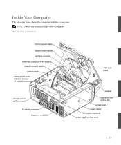
Inside Your Computer The following figure shows the computer with the cover open. Inside the Computer interior service label diskette drive bracket hard-drive bracket externally accessible-drive bracket chassis intrusion switch control panel memory riser board retention bracket (if needed) microprocessor airflow shroud I/O panel connectors expansion-card slots AGP card brace speaker expansion-card cooling fan system board power supply AC power receptacle power supply airflow vents 21 NOTE: User service access points are color-coded green.
Inside Your Computer The following figure shows the computer with the cover open. Inside the Computer interior service label diskette drive bracket hard-drive bracket externally accessible-drive bracket chassis intrusion switch control panel memory riser board retention bracket (if needed) microprocessor airflow shroud I/O panel connectors expansion-card slots AGP card brace speaker expansion-card cooling fan system board power supply AC power receptacle power supply airflow vents 21 NOTE: User service access points are color-coded green.

Service Manual
Page 23
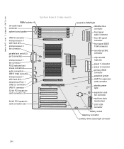
System Board Components Components The following figure shows the principal connectors and components on the system board. 23
System Board Components Components The following figure shows the principal connectors and components on the system board. 23
Service Manual
Page 24
www.dell.com | support.dell.com RIMM sockets (4) CD audio input connector system board speaker System Board Components VRM 0 connector microprocessor 0 with heat sink microprocessor 0 fan connector parallel and serial (2) port connectors microprocessor 1 fan connector PS/2 keyboard and mouse connectors audio connectors ...
www.dell.com | support.dell.com RIMM sockets (4) CD audio input connector system board speaker System Board Components VRM 0 connector microprocessor 0 with heat sink microprocessor 0 fan connector parallel and serial (2) port connectors microprocessor 1 fan connector PS/2 keyboard and mouse connectors audio connectors ...

Service Manual
Page 25
System Board Labels Connector or Component 1394 AGP AUDIO AUX_LED BATTERY CD_IN CPU_0 CPU_1 DISKETTE FAN_CCAG FAN_P0 FAN_P1 FP3AUDIO FRONT1394 IDE1 IDE2 KYBD_MOUSE PANEL PARALLEL_SERIAL PCIn POWER1 ... 2 connector Password jumper RIMM socket Real-time clock reset jumper 25 Labels The following table lists the labels for connectors and components on the system board, and briefly describes the function of each.
System Board Labels Connector or Component 1394 AGP AUDIO AUX_LED BATTERY CD_IN CPU_0 CPU_1 DISKETTE FAN_CCAG FAN_P0 FAN_P1 FP3AUDIO FRONT1394 IDE1 IDE2 KYBD_MOUSE PANEL PARALLEL_SERIAL PCIn POWER1 ... 2 connector Password jumper RIMM socket Real-time clock reset jumper 25 Labels The following table lists the labels for connectors and components on the system board, and briefly describes the function of each.

Service Manual
Page 26
... PSWD RTCRST NOTICE: Before changing a jumper setting, verify that the standby power light on the system board. To locate this light, see "System Board Components." Otherwise, damage to -RAM light Telephony connector Network and Port 2 USB (2) connectors VRM 0 connector VRM 1 ...connector Jumpers The following figure shows the location of the jumpers on the system board has turned off its pin(s) and carefully fit it down onto the pin(s) indicated. 26 www.dell.com | support.dell.com S y s t e m B o a r d L a b e l s (continued) Connector or Component SCSI SPKR ...
... PSWD RTCRST NOTICE: Before changing a jumper setting, verify that the standby power light on the system board. To locate this light, see "System Board Components." Otherwise, damage to -RAM light Telephony connector Network and Port 2 USB (2) connectors VRM 0 connector VRM 1 ...connector Jumpers The following figure shows the location of the jumpers on the system board has turned off its pin(s) and carefully fit it down onto the pin(s) indicated. 26 www.dell.com | support.dell.com S y s t e m B o a r d L a b e l s (continued) Connector or Component SCSI SPKR ...

Service Manual
Page 27
System-Board Jumper Settings Jumper Setting Description PSWD (default) Password features are disabled. Can be used for troubleshooting. jumpered unjumpered 27 Password features are enabled. RTCRST Real-time clock reset. The following table lists the system board jumpers and their settings.
System-Board Jumper Settings Jumper Setting Description PSWD (default) Password features are disabled. Can be used for troubleshooting. jumpered unjumpered 27 Password features are enabled. RTCRST Real-time clock reset. The following table lists the system board jumpers and their settings.
Service Manual
Page 41
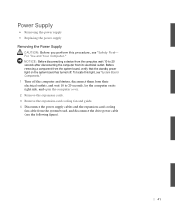
...• Removing the power supply • Replacing the power supply Removing the Power Supply CAUTION: Before you perform this light, see "System Board Components." 1 Turn off . NOTICE: Before disconnecting a device from the computer, wait 10 to 20 seconds, lay the computer on the system... their electrical outlets, and wait 10 to 20 seconds after disconnecting the computer from the system board, and disconnect the drive power cable (see "Safety First- Before removing a component from the system board, verify that the standby power light on its right side, and open the computer cover. ...
...• Removing the power supply • Replacing the power supply Removing the Power Supply CAUTION: Before you perform this light, see "System Board Components." 1 Turn off . NOTICE: Before disconnecting a device from the computer, wait 10 to 20 seconds, lay the computer on the system... their electrical outlets, and wait 10 to 20 seconds after disconnecting the computer from the system board, and disconnect the drive power cable (see "Safety First- Before removing a component from the system board, verify that the standby power light on its right side, and open the computer cover. ...

Service Manual
Page 44
b Slide the cable retainer to the system board, and connect the drive power cable. 6 Replace the expansion-card cooling fan and guide. 7 Install the expansion cards. 8 Close the computer cover and restart the computer. 44 www.dell.com | support.dell.com a Place the cable retainer into place. 5 Connect the power supply cables and the expansion-card cooling fan cable to the left until it locks into the four securing slots in the chassis.
b Slide the cable retainer to the system board, and connect the drive power cable. 6 Replace the expansion-card cooling fan and guide. 7 Install the expansion cards. 8 Close the computer cover and restart the computer. 44 www.dell.com | support.dell.com a Place the cable retainer into place. 5 Connect the power supply cables and the expansion-card cooling fan cable to the left until it locks into the four securing slots in the chassis.
Service Manual
Page 45
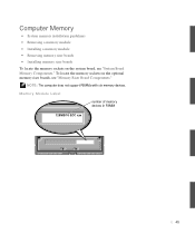
To locate the memory sockets on the system board, see "Memory Riser Board Components." Memory Module Label number of memory devices in RIMM 128MB/16 ECC xxx 45 NOTE: The computer does not support RIMMs with six memory devices. Computer Memory • System memory installation guidelines • Removing a memory module • Installing a memory module • Removing memory riser boards • Installing memory riser boards To locate the memory sockets on the optional memory riser boards, see "System Board Memory Components."
To locate the memory sockets on the system board, see "Memory Riser Board Components." Memory Module Label number of memory devices in RIMM 128MB/16 ECC xxx 45 NOTE: The computer does not support RIMMs with six memory devices. Computer Memory • System memory installation guidelines • Removing a memory module • Installing a memory module • Removing memory riser boards • Installing memory riser boards To locate the memory sockets on the optional memory riser boards, see "System Board Memory Components."
Service Manual
Page 47
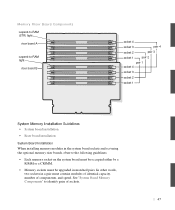
... 4 socket 3 socket 2 socket 1 System Memory Installation Guidelines • System board installation • Riser board installation System Board Installation When installing memory modules in the system board sockets and not using the optional memory riser boards, observe the following guidelines: • Each memory socket on the system board must be occupied either by a RIMM or a CRIMM. •...
... 4 socket 3 socket 2 socket 1 System Memory Installation Guidelines • System board installation • Riser board installation System Board Installation When installing memory modules in the system board sockets and not using the optional memory riser boards, observe the following guidelines: • Each memory socket on the system board must be occupied either by a RIMM or a CRIMM. •...

Service Manual
Page 48
... can either be installed in the other words, two sockets in system board memory sockets 1 and 2. www.dell.com | support.dell.com • Mixed pairs of ECC and non-ECC modules all function as non-ECC. • The optional memory riser boards only support PC800 memory modules. For example, if the first and second...
... can either be installed in the other words, two sockets in system board memory sockets 1 and 2. www.dell.com | support.dell.com • Mixed pairs of ECC and non-ECC modules all function as non-ECC. • The optional memory riser boards only support PC800 memory modules. For example, if the first and second...
Service Manual
Page 50
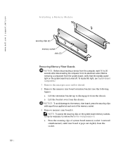
... from the socket. 50 To locate this light, see "System Board Components." 1 Remove the microprocessor airflow shroud. 2 Remove the memory riser board retention bracket (see the following figure). www.dell.com | support.dell.com Installing a Memory Module securing clips (2) memory socket slots (2) Removing Memory Riser Boards NOTICE: Before disconnecting a device from the computer, wait 10...
... from the socket. 50 To locate this light, see "System Board Components." 1 Remove the microprocessor airflow shroud. 2 Remove the memory riser board retention bracket (see the following figure). www.dell.com | support.dell.com Installing a Memory Module securing clips (2) memory socket slots (2) Removing Memory Riser Boards NOTICE: Before disconnecting a device from the computer, wait 10...
Service Manual
Page 51
b Lift riser board B away from the socket. b Lift riser board A away from the retention brackets on riser board B. 4 Remove memory riser board B: a Press the securing clips of system board memory socket B outward simultaneously until riser board B pops out slightly from socket 2. 51
b Lift riser board B away from the socket. b Lift riser board A away from the retention brackets on riser board B. 4 Remove memory riser board B: a Press the securing clips of system board memory socket B outward simultaneously until riser board B pops out slightly from socket 2. 51
Service Manual
Page 53
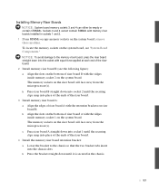
...insert into the socket with equal force applied at the ends of the riser board. 4 Install the memory riser board retention bracket: a Lower the bracket to the memory riser board, press the riser board straight down into socket 2 until the securing clips snap into place at the... ends of the riser board. 3 Install memory riser board A: a Align the edges of riser board A with the retention brackets on riser board B. Installing Memory Riser Boards NOTICE: System board memory sockets 3 and 4 can either be empty or contain CRIMMs. Sockets 3...
...insert into the socket with equal force applied at the ends of the riser board. 4 Install the memory riser board retention bracket: a Lower the bracket to the memory riser board, press the riser board straight down into socket 2 until the securing clips snap into place at the... ends of the riser board. 3 Install memory riser board A: a Align the edges of riser board A with the retention brackets on riser board B. Installing Memory Riser Boards NOTICE: System board memory sockets 3 and 4 can either be empty or contain CRIMMs. Sockets 3...


