Service Manual
Page 24
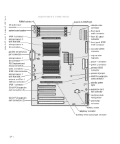
www.dell.com | support.dell.com RIMM sockets (4) CD audio input connector system board speaker System Board Components VRM 0 connector microprocessor 0 with heat sink microprocessor 0 fan connector parallel and serial (2) ... microprocessor 1 with heat sink network and Port 1 USB (2) connectors VRM 1 connector 32-bit PCI expansion card connectors (3) 64-bit PCI expansion card connectors (2) suspend-to-RAM light diskette-drive connector front panel audio connector front I/O panel connector front panel IEEE 1394 connector secondary EIDE connector chip set with heat sink power...
www.dell.com | support.dell.com RIMM sockets (4) CD audio input connector system board speaker System Board Components VRM 0 connector microprocessor 0 with heat sink microprocessor 0 fan connector parallel and serial (2) ... microprocessor 1 with heat sink network and Port 1 USB (2) connectors VRM 1 connector 32-bit PCI expansion card connectors (3) 64-bit PCI expansion card connectors (2) suspend-to-RAM light diskette-drive connector front panel audio connector front I/O panel connector front panel IEEE 1394 connector secondary EIDE connector chip set with heat sink power...

Service Manual
Page 26
Otherwise, damage to -RAM light Telephony connector Network and Port 2 USB (2) connectors VRM 0 connector VRM 1 connector Jumpers The following figure shows the location of the jumpers on the system ... the plug off . System Board Jumpers PSWD RTCRST NOTICE: Before changing a jumper setting, verify that the standby power light on the system board. www.dell.com | support.dell.com S y s t e m B o a r d L a b e l s (continued) Connector or Component SCSI SPKR STANDBY_LED STR_LED TAPI/MODEM USB_NIC VRM_0 VRM_1 Label LVD SCSI connector System board speaker Standby power light...
Otherwise, damage to -RAM light Telephony connector Network and Port 2 USB (2) connectors VRM 0 connector VRM 1 connector Jumpers The following figure shows the location of the jumpers on the system ... the plug off . System Board Jumpers PSWD RTCRST NOTICE: Before changing a jumper setting, verify that the standby power light on the system board. www.dell.com | support.dell.com S y s t e m B o a r d L a b e l s (continued) Connector or Component SCSI SPKR STANDBY_LED STR_LED TAPI/MODEM USB_NIC VRM_0 VRM_1 Label LVD SCSI connector System board speaker Standby power light...
Service Manual
Page 47
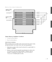
...) light riser board A suspend-to identify pairs of components, and speed. See "System Board Memory Components" to -RAM light riser board B socket 4 socket 3 pair 4 socket 2 pair 3 socket 1 pair 2 pair 1 socket 4 socket 3 socket 2 socket 1 System Memory Installation Guidelines • System board installation • Riser ...
...) light riser board A suspend-to identify pairs of components, and speed. See "System Board Memory Components" to -RAM light riser board B socket 4 socket 3 pair 4 socket 2 pair 3 socket 1 pair 2 pair 1 socket 4 socket 3 socket 2 socket 1 System Memory Installation Guidelines • System board installation • Riser ...
Memory Riser Board Replacement
Page 9
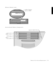
Memory Module L abel 128MB/16 ECC xxx number of memory devices in RIMM System Board Memory Components pair 2 pair 1 socket 4 socket 3 socket 2 socket 1 suspend-to-RAM (STR) light Memory Riser Board Replacement 9
Memory Module L abel 128MB/16 ECC xxx number of memory devices in RIMM System Board Memory Components pair 2 pair 1 socket 4 socket 3 socket 2 socket 1 suspend-to-RAM (STR) light Memory Riser Board Replacement 9
Memory Riser Board Replacement
Page 10
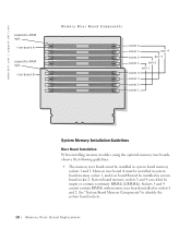
See "System Board Memory Components" to -RAM light riser board B Memory Riser Board Components socket 4 socket 3 pair 4 socket 2 pair 3 socket 1 pair 2 pair 1 socket 4 socket 3 socket 2 socket 1 System Memory Installation Guidelines Riser Board ... A must be installed in sockets 1 and 2. Sockets 3 and 4 cannot contain RIMMs with memory riser boards installed in system board memory sockets 1 and 2. com suspend-to-RAM light riser board A suspend-to identify the system board sockets. 10 M em o r y Ri s e r B o a rd Rep l a c em e n t w w w.d el l.co m | su p po rt...
See "System Board Memory Components" to -RAM light riser board B Memory Riser Board Components socket 4 socket 3 pair 4 socket 2 pair 3 socket 1 pair 2 pair 1 socket 4 socket 3 socket 2 socket 1 System Memory Installation Guidelines Riser Board ... A must be installed in sockets 1 and 2. Sockets 3 and 4 cannot contain RIMMs with memory riser boards installed in system board memory sockets 1 and 2. com suspend-to-RAM light riser board A suspend-to identify the system board sockets. 10 M em o r y Ri s e r B o a rd Rep l a c em e n t w w w.d el l.co m | su p po rt...


