User Manual
Page 7
... Release Windows Storage Server 2008 provides an efficient and unified file management by extending and consolidating the management interface. 1 Overview Dell Network Attached Storage (NAS) systems run the Microsoft Windows Storage Server 2008 operating system, which provides a user interface for:... • Initial system configuration • Unified storage appliance management • Simplified setup • Management of storage and shared folders Windows Storage Server 2008 is specially tuned to provide optimal performance for Administration ...
... Release Windows Storage Server 2008 provides an efficient and unified file management by extending and consolidating the management interface. 1 Overview Dell Network Attached Storage (NAS) systems run the Microsoft Windows Storage Server 2008 operating system, which provides a user interface for:... • Initial system configuration • Unified storage appliance management • Simplified setup • Management of storage and shared folders Windows Storage Server 2008 is specially tuned to provide optimal performance for Administration ...

User Manual
Page 32
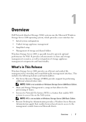
...7 Review the Installation Results window to verify that the installation succeeded. 8 Click Close to the Active Directory Lightweight Directory Services Setup Wizard window, click Next. 3 On the Setup Options window, select a unique instance, and then click Next. 4 On the Instance Name window, type a name for ... New AD LDS Instance To create a new AD LDS instance: 1 Click Start Administrative Tools Active Directory Lightweight Directory Services Setup Wizard. 2 On the Welcome to exit the wizard. NOTE: The Before You Begin window is not displayed if the Skip this example,...
...7 Review the Installation Results window to verify that the installation succeeded. 8 Click Close to the Active Directory Lightweight Directory Services Setup Wizard window, click Next. 3 On the Setup Options window, select a unique instance, and then click Next. 4 On the Instance Name window, type a name for ... New AD LDS Instance To create a new AD LDS instance: 1 Click Start Administrative Tools Active Directory Lightweight Directory Services Setup Wizard. 2 On the Welcome to exit the wizard. NOTE: The Before You Begin window is not displayed if the Skip this example,...

User Manual
Page 34
... Edit to open an elevated command prompt. 2 Navigate to the C:\WINDOWS\ADAM directory, and then type the following in the Active Directory Lightweight Directory Services Setup Wizard, use that value instead. 3 Click OK. ADSI Edit refreshes to . The strings "cn=Configuration,dc=X" and #configurationNamingContext should not be modified. a Under Connection Point...
... Edit to open an elevated command prompt. 2 Navigate to the C:\WINDOWS\ADAM directory, and then type the following in the Active Directory Lightweight Directory Services Setup Wizard, use that value instead. 3 Click OK. ADSI Edit refreshes to . The strings "cn=Configuration,dc=X" and #configurationNamingContext should not be modified. a Under Connection Point...
User Manual
Page 39
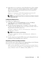
... to log account mapping failures to the Windows Event Log service by setting the following : nfsadmin mapping config adlookup=yes addomain= server1:389 3 Test the setup by accessing the NFS resources and verifying that the user and group account mappings work as follows: dsacls "\\server1:389\CN=nfsadldsinstance,dc= server1" /G "anonymous...
... to log account mapping failures to the Windows Event Log service by setting the following : nfsadmin mapping config adlookup=yes addomain= server1:389 3 Test the setup by accessing the NFS resources and verifying that the user and group account mappings work as follows: dsacls "\\server1:389\CN=nfsadldsinstance,dc= server1" /G "anonymous...

Hardware Owner's Manual
Page 4
... and UEFI Boot Manager 57 Choosing the System Boot Mode 57 Entering the System Setup Program 58 System Setup Options 59 Entering the UEFI Boot Manager 69 System and Setup Password Features 72 Embedded System Management 75 Baseboard Management Controller Configuration 76 iDRAC Configuration Utility 77 3 Installing System Components 79 Recommended Tools 79...
... and UEFI Boot Manager 57 Choosing the System Boot Mode 57 Entering the System Setup Program 58 System Setup Options 59 Entering the UEFI Boot Manager 69 System and Setup Password Features 72 Embedded System Management 75 Baseboard Management Controller Configuration 76 iDRAC Configuration Utility 77 3 Installing System Components 79 Recommended Tools 79...

Hardware Owner's Manual
Page 9
... on page 57. Starts PXE boot. For more information, see the Unified Server Configurator documentation. Keystroke Description Enters the System Setup program. Enters System Services, which allows access to the system event log (SEL) and configuration of remote access to access utilities... such as embedded system diagnostics. For more information. See "Using the System Setup Program and UEFI Boot Manager" on page 57. Enters the Baseboard Management Controller (BMC) or iDRAC Configuration Utility, which opens the ...
... on page 57. Starts PXE boot. For more information, see the Unified Server Configurator documentation. Keystroke Description Enters the System Setup program. Enters System Services, which allows access to the system event log (SEL) and configuration of remote access to access utilities... such as embedded system diagnostics. For more information. See "Using the System Setup Program and UEFI Boot Manager" on page 57. Enters the Baseboard Management Controller (BMC) or iDRAC Configuration Utility, which opens the ...

Hardware Owner's Manual
Page 14
Setup Menu Option Description BMC or DRAC Select DHCP or Static IP to display LCD error messages in a format that can be displayed on the LCD ... (Gtw). If Static IP is selected, the available fields are available. This can be selected to be useful when trying to view domain addresses. Select Setup DNS to system, the BMC option is installed on page 23 for a list of messages in this format.
Setup Menu Option Description BMC or DRAC Select DHCP or Static IP to display LCD error messages in a format that can be displayed on the LCD ... (Gtw). If Static IP is selected, the available fields are available. This can be selected to be useful when trying to view domain addresses. Select Setup DNS to system, the BMC option is installed on page 23 for a list of messages in this format.

Hardware Owner's Manual
Page 15
... can be configured in the "Set home" submenu of the system in the "Set home" submenu of the Setup menu (see "Setup Menu" on page 14). Temperature Displays the temperature of the Setup menu (see "Setup Menu" on page 14). View Menu Option Description BMC IP or DRAC IP Displays the IPv4 or IPv6...
... can be configured in the "Set home" submenu of the system in the "Set home" submenu of the Setup menu (see "Setup Menu" on page 14). Temperature Displays the temperature of the Setup menu (see "Setup Menu" on page 14). View Menu Option Description BMC IP or DRAC IP Displays the IPv4 or IPv6...

Hardware Owner's Manual
Page 19
The NIC is being sent or received. Network data is connected to a valid network link at 10/100 Mbps. See "Using the System Setup Program and UEFI Boot Manager" on page 57. NIC Indicators 1 2 1 link indicator 2 activity indicator Indicator Link and activity indicators are off power to the system ... external device. Guidelines for the attached device has been installed on the system. • If necessary to enable ports on your system, use the System Setup program. NIC Indicator Codes Figure 1-5. The NIC is not connected to the network. About Your System 19
The NIC is being sent or received. Network data is connected to a valid network link at 10/100 Mbps. See "Using the System Setup Program and UEFI Boot Manager" on page 57. NIC Indicators 1 2 1 link indicator 2 activity indicator Indicator Link and activity indicators are off power to the system ... external device. Guidelines for the attached device has been installed on the system. • If necessary to enable ports on your system, use the System Setup program. NIC Indicator Codes Figure 1-5. The NIC is not connected to the network. About Your System 19

Hardware Owner's Manual
Page 23
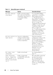
The LCD messages refer to events recorded in the System Setup program. in the System Event Log (SEL). log for at least five seconds until an ... LCD provides status messages to indicate an error condition. support. Table 1-2. See "Using the following conditions: System Setup Program • The system is for can change the system ID and name in The SYSTEM NAME the System... Setup displays under the program. You can be defined by descriptive text. NOTE: If your system fails to...
The LCD messages refer to events recorded in the System Setup program. in the System Event Log (SEL). log for at least five seconds until an ... LCD provides status messages to indicate an error condition. support. Table 1-2. See "Using the following conditions: System Setup Program • The system is for can change the system ID and name in The SYSTEM NAME the System... Setup displays under the program. You can be defined by descriptive text. NOTE: If your system fails to...

Hardware Owner's Manual
Page 38
... Memory Mode. The system will reboot. System Messages Message Causes Corrective Actions 128-bit Advanced ECC mode disabled. Pairs must be matched in the system setup program, but is not functioning properly or has not completed initialization. Alert! Advanced ECC Memory Mode was enabled in a configuration that supports Advanced ECC Memory...
... Memory Mode. The system will reboot. System Messages Message Causes Corrective Actions 128-bit Advanced ECC mode disabled. Pairs must be matched in the system setup program, but is not functioning properly or has not completed initialization. Alert! Advanced ECC Memory Mode was enabled in a configuration that supports Advanced ECC Memory...

Hardware Owner's Manual
Page 40
Power required exceeds PSU wattage. See "Power Supplies" on page 154. Alert! See system setup program, but "Troubleshooting System the current configuration Memory" on page 88. Table 1-3. Alert! Memory configuration does not support redundant memory. System Messages (continued) Message Causes ... without this power supply. See "Using may be supported by the power supplies. An error caused the system to Check other system reboot. the System Setup Program and UEFI Boot Manager" on page 57.
Power required exceeds PSU wattage. See "Power Supplies" on page 154. Alert! See system setup program, but "Troubleshooting System the current configuration Memory" on page 88. Table 1-3. Alert! Memory configuration does not support redundant memory. System Messages (continued) Message Causes ... without this power supply. See "Using may be supported by the power supplies. An error caused the system to Check other system reboot. the System Setup Program and UEFI Boot Manager" on page 57.

Hardware Owner's Manual
Page 41
...installed with no memory. System Messages (continued) Message Causes Corrective Actions BIOS MANUFACTURING MODE detected. out of manufacturing mode. Please run SETUP NVRAM_CLR jumper is installed on page 115. CPU set lower for check any other system power conservation. BIOS Update Remote BIOS update ...See "System Memory" on system board. If problem persists, see "Getting Help" on page 57. See "Using the System Setup Program and UEFI Boot Manager" on page 177. messages for normal operation. Memory modules are required but not installed in the clear setting...
...installed with no memory. System Messages (continued) Message Causes Corrective Actions BIOS MANUFACTURING MODE detected. out of manufacturing mode. Please run SETUP NVRAM_CLR jumper is installed on page 115. CPU set lower for check any other system power conservation. BIOS Update Remote BIOS update ...See "System Memory" on system board. If problem persists, see "Getting Help" on page 57. See "Using the System Setup Program and UEFI Boot Manager" on page 177. messages for normal operation. Memory modules are required but not installed in the clear setting...

Hardware Owner's Manual
Page 42
... boot Ensure that the boot mode is because UEFI boot mode is non- Ensure that the processors are properly installed. Use the system setup program to UEFI. have Ensure that the enabled in the system. See "Using the UEFI. See "Troubleshooting System Memory" on page...operating system is set to change the boot mode as needed. Table 1-3. memory modules. System halted Current boot mode is available. System Setup Program and UEFI Boot Manager" on page 57. available. CPUs with different cache sizes detected. CPUs with different power rating detected! ...
... boot Ensure that the boot mode is because UEFI boot mode is non- Ensure that the processors are properly installed. Use the system setup program to UEFI. have Ensure that the enabled in the system. See "Using the UEFI. See "Troubleshooting System Memory" on page...operating system is set to change the boot mode as needed. Table 1-3. memory modules. System halted Current boot mode is available. System Setup Program and UEFI Boot Manager" on page 57. available. CPUs with different cache sizes detected. CPUs with different power rating detected! ...

Hardware Owner's Manual
Page 43
...The memory module configuration for NIC settings. Defective mouse or keyboard. Gate A20 failure Faulty keyboard controller; See "Using the System Setup Program and UEFI Boot Manager" on faulty system board. Management Shared NIC= Check the system management software or the System... Setup program for each CPU should match. An invalid system configuration caused a system halt. System Messages (continued) Message Causes Corrective Actions DIMM...
...The memory module configuration for NIC settings. Defective mouse or keyboard. Gate A20 failure Faulty keyboard controller; See "Using the System Setup Program and UEFI Boot Manager" on faulty system board. Management Shared NIC= Check the system management software or the System... Setup program for each CPU should match. An invalid system configuration caused a system halt. System Messages (continued) Message Causes Corrective Actions DIMM...

Hardware Owner's Manual
Page 44
page 177. Power down and restart the system from the power button, and then enter the System Setup program to take the system mode. See "Entering the System Setup Program" on page 115. Manufacturing mode detected System is in manufacturing Reboot to enable the USB port... storage controller slot. See "RAID Battery (Optional)" on page 113. If operating locally, power cycle the system and enter system setup program to change settings. Memory Initialization Warning: Memory size may not work because all user accessible USB ports are disabled in the dedicated...
page 177. Power down and restart the system from the power button, and then enter the System Setup program to take the system mode. See "Entering the System Setup Program" on page 115. Manufacturing mode detected System is in manufacturing Reboot to enable the USB port... storage controller slot. See "RAID Battery (Optional)" on page 113. If operating locally, power cycle the system and enter system setup program to change settings. Memory Initialization Warning: Memory size may not work because all user accessible USB ports are disabled in the dedicated...
Hardware Owner's Manual
Page 46
... or no operating system on page 177. Check the hard drive configuration settings in the specified slot number. See "Using the System Setup Program and UEFI Boot Manager" on page 161. See "Troubleshooting Expansion Cards" on page 57. Reseat the PCIe card in the System... operating system on page 177. 46 About Your System See your hard drive. PCIe Training Faulty or improperly Error: Expected installed PCIe card in System Setup program, or no bootable USB key installed. If the problem persists, see "Troubleshooting an Optical Drive" on page 157, "Troubleshooting a USB Device"...
... or no operating system on page 177. Check the hard drive configuration settings in the specified slot number. See "Using the System Setup Program and UEFI Boot Manager" on page 161. See "Troubleshooting Expansion Cards" on page 57. Reseat the PCIe card in the System... operating system on page 177. 46 About Your System See your hard drive. PCIe Training Faulty or improperly Error: Expected installed PCIe card in System Setup program, or no bootable USB key installed. If the problem persists, see "Troubleshooting an Optical Drive" on page 157, "Troubleshooting a USB Device"...

Hardware Owner's Manual
Page 49
... Actions Invalid memory configuration. The following DIMMs should match in rank count: x,x,... Time-of -day clock stopped Faulty battery or faulty chip. faulty system SETUP program battery. The following DIMMs should match in size and geometry: x,x,... If the problem persists, replace the system battery. See "System Battery" on page ... sensor is installed in geometry: x,x,... See "Troubleshooting the System Battery" on page 57. Check the Time and Date settings. See "Using the System Setup Program and UEFI Boot Manager" on page 152. About Your System 49
... Actions Invalid memory configuration. The following DIMMs should match in rank count: x,x,... Time-of -day clock stopped Faulty battery or faulty chip. faulty system SETUP program battery. The following DIMMs should match in size and geometry: x,x,... If the problem persists, replace the system battery. See "System Battery" on page ... sensor is installed in geometry: x,x,... See "Troubleshooting the System Battery" on page 57. Check the Time and Date settings. See "Using the System Setup Program and UEFI Boot Manager" on page 152. About Your System 49

Hardware Owner's Manual
Page 52
... Mode, or change the Modules in the specified memory mode to Optimized or Sparing in the BIOS setup screen. DIMM's installed in the following slot are unused. Unused memory detected. or Sparing in the BIOS setup screen. Warning: A fatal A fatal system error occurred Check the SEL for Advanced Advanced ECC Memory ECC...
... Mode, or change the Modules in the specified memory mode to Optimized or Sparing in the BIOS setup screen. DIMM's installed in the following slot are unused. Unused memory detected. or Sparing in the BIOS setup screen. Warning: A fatal A fatal system error occurred Check the SEL for Advanced Advanced ECC Memory ECC...

Hardware Owner's Manual
Page 57
...; Enable or disable integrated devices • Set performance and power management thresholds • Manage system security Choosing the System Boot Mode The System Setup program also enables you to manage your system hardware and specify BIOS-level options. See "Entering the UEFI Boot Manager" on page 69 for more... information on page 63. See "Boot Settings Screen" on this interface. Using the System Setup Program and UEFI Boot Manager 57 Once you specify the boot mode, the system boots in the Boot Mode field of the Boot Settings screen...
...; Enable or disable integrated devices • Set performance and power management thresholds • Manage system security Choosing the System Boot Mode The System Setup program also enables you to manage your system hardware and specify BIOS-level options. See "Entering the UEFI Boot Manager" on page 69 for more... information on page 63. See "Boot Settings Screen" on this interface. Using the System Setup Program and UEFI Boot Manager 57 Once you specify the boot mode, the system boots in the Boot Mode field of the Boot Settings screen...


