Information Update
Page 3
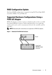
... 6/E. With redundant paths, if one path fails, another path can detect and use redundant paths to communicate between the controller and the hard drive. RAID Configuration Update Host-based RAID configuration is not supported on PERC 5/E adapters. Supported Hardware Configurations Using a PERC 6/E Adapter PERC 6/E adapters can be used to drives in a Dell PowerVault MD1000 enclosure.
... 6/E. With redundant paths, if one path fails, another path can detect and use redundant paths to communicate between the controller and the hard drive. RAID Configuration Update Host-based RAID configuration is not supported on PERC 5/E adapters. Supported Hardware Configurations Using a PERC 6/E Adapter PERC 6/E adapters can be used to drives in a Dell PowerVault MD1000 enclosure.
Information Update
Page 5
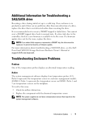
... The system management software displays four temperature probes (0-3). For more information about troubleshooting a SAS/SATA drive, see the Dell PowerVault MD1000 Storage Enclosure Hardware Owner's Manual at support.dell.com/manuals. If a firmware update does not fix the issue, replace the drive. It cannot be replaced. Probe 0 represents the temperature sensor on EMM1. You cannot reset...
... The system management software displays four temperature probes (0-3). For more information about troubleshooting a SAS/SATA drive, see the Dell PowerVault MD1000 Storage Enclosure Hardware Owner's Manual at support.dell.com/manuals. If a firmware update does not fix the issue, replace the drive. It cannot be replaced. Probe 0 represents the temperature sensor on EMM1. You cannot reset...

MD1000 Systems Support Matrix
Page 2
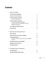
Table of Contents Supported RAID Controllers 3 PERC 5/E Adapter ...3 PERC 6/E Adapter ...4 Supported Servers ...4 Supported Operating Systems 5 Supported Management Software 5 Supported Hard Drives 5 Supported Hardware Configurations 8 2
Table of Contents Supported RAID Controllers 3 PERC 5/E Adapter ...3 PERC 6/E Adapter ...4 Supported Servers ...4 Supported Operating Systems 5 Supported Management Software 5 Supported Hard Drives 5 Supported Hardware Configurations 8 2
MD1000 Systems Support Matrix
Page 5
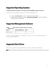
Minimum Supported Management Software for PowerVault MD1000 Systems Software Minimum OMSA Revision Notes Dell OpenManage™ 5.3 The minimum supported OMSA version for MD1000 is displayed, then the drive has shipped with the required minimum firmware level for support 5 NOTE: If no minimum firmware level is 5.3. Refer to see the latest supported Operating Systems ...
Minimum Supported Management Software for PowerVault MD1000 Systems Software Minimum OMSA Revision Notes Dell OpenManage™ 5.3 The minimum supported OMSA version for MD1000 is displayed, then the drive has shipped with the required minimum firmware level for support 5 NOTE: If no minimum firmware level is 5.3. Refer to see the latest supported Operating Systems ...
MD1000 Systems Support Matrix
Page 6
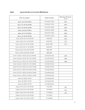
Table 4. Supported Hard Drives for PowerVault MD1000 Systems Drive description Maxtor SAS 73 GB 10K RPM Maxtor SAS 146 GB 10K RPM Maxtor SAS 300 GB 10K RPM Maxtor SAS 36 GB 15K RPM ...
Table 4. Supported Hard Drives for PowerVault MD1000 Systems Drive description Maxtor SAS 73 GB 10K RPM Maxtor SAS 146 GB 10K RPM Maxtor SAS 300 GB 10K RPM Maxtor SAS 36 GB 15K RPM ...

MD1000 Systems Support Matrix
Page 9
...redundant paths, if one path fails, another path can detect and use redundant paths to communicate between the controller and the hard drive. NOTE: Redundant Path connectivity is not supported on a Single PERC 5/E or PERC 6/E Controller (both ports connected) Unified Mode... single-HBA host server The PERC 6/E adapter can be used to drives contained in an MD1000 enclosure. Figure 1. Max Configuration on PERC 5/E 9 Supported Hardware Configuration Unified Mode Split Mode Two-host configuration Host controller Host ...
...redundant paths, if one path fails, another path can detect and use redundant paths to communicate between the controller and the hard drive. NOTE: Redundant Path connectivity is not supported on a Single PERC 5/E or PERC 6/E Controller (both ports connected) Unified Mode... single-HBA host server The PERC 6/E adapter can be used to drives contained in an MD1000 enclosure. Figure 1. Max Configuration on PERC 5/E 9 Supported Hardware Configuration Unified Mode Split Mode Two-host configuration Host controller Host ...
Hardware Owners Manual
Page 3
...About Your System Other Information You May Need 7 Indicators on the Enclosure Bezel 8 Front-Panel Indicators and Features 9 Drive Carrier LED Indicators 10 Back-Panel Indicators and Features 11 Enclosure Management Module (EMM 12 Enclosure Failover When Two EMMs ...Before You Begin 19 Cabling Your Enclosure for Unified or Split Mode 19 Connecting the Enclosure 20 Using Your Enclosure to Expand a Dell PowerVault MD3000 Enclosure 21 Changing Your Enclosure's Operating Mode 24 Managing Your Storage Enclosure 25 Downloading Firmware 25 3 Installing Enclosure Components Recommended Tools...
...About Your System Other Information You May Need 7 Indicators on the Enclosure Bezel 8 Front-Panel Indicators and Features 9 Drive Carrier LED Indicators 10 Back-Panel Indicators and Features 11 Enclosure Management Module (EMM 12 Enclosure Failover When Two EMMs ...Before You Begin 19 Cabling Your Enclosure for Unified or Split Mode 19 Connecting the Enclosure 20 Using Your Enclosure to Expand a Dell PowerVault MD3000 Enclosure 21 Changing Your Enclosure's Operating Mode 24 Managing Your Storage Enclosure 25 Downloading Firmware 25 3 Installing Enclosure Components Recommended Tools...
Hardware Owners Manual
Page 4
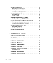
Removing and Installing Drives 28 Removing Drives from the Enclosure 29 Installing SAS Drives in the Enclosure 30 Installing SATA Drives in the Enclosure 32 Removing and Installing an EMM 34 Removing an EMM 34 Installing an EMM 35 Installing an EMM Module Cover in an ... 45 Troubleshooting a Wet Enclosure 45 Troubleshooting a Damaged Enclosure 46 Troubleshooting Power Supplies 46 Troubleshooting Enclosure Cooling Problems 47 Troubleshooting a Fan 48 Troubleshooting SAS and SATA Drives 48 Troubleshooting Enclosure Connections 49 4 Contents
Removing and Installing Drives 28 Removing Drives from the Enclosure 29 Installing SAS Drives in the Enclosure 30 Installing SATA Drives in the Enclosure 32 Removing and Installing an EMM 34 Removing an EMM 34 Installing an EMM 35 Installing an EMM Module Cover in an ... 45 Troubleshooting a Wet Enclosure 45 Troubleshooting a Damaged Enclosure 46 Troubleshooting Power Supplies 46 Troubleshooting Enclosure Cooling Problems 47 Troubleshooting a Fan 48 Troubleshooting SAS and SATA Drives 48 Troubleshooting Enclosure Connections 49 4 Contents
Hardware Owners Manual
Page 7
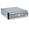
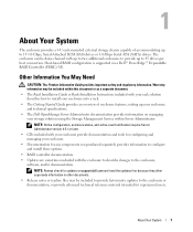
... overview of accommodating up to 15 3.0-Gbps, Serial-Attached SCSI (SAS) drives or 3.0-Gbps Serial ATA (SATA) drives. Warranty information may be daisy-chained with the enclosure to describe changes to 45 drives per host connection. 1 About Your System The enclosure provides a 3-U rack...other documents. • Release notes or readme files may be included within Server Administrator. Host-based RAID configuration is supported via a Dell™ PowerEdge™ Expandable RAID Controller (PERC) 5/E. About Your System 7 The enclosure can be included to provide last-minute ...
... overview of accommodating up to 15 3.0-Gbps, Serial-Attached SCSI (SAS) drives or 3.0-Gbps Serial ATA (SATA) drives. Warranty information may be daisy-chained with the enclosure to describe changes to 45 drives per host connection. 1 About Your System The enclosure provides a 3-U rack...other documents. • Release notes or readme files may be included within Server Administrator. Host-based RAID configuration is supported via a Dell™ PowerEdge™ Expandable RAID Controller (PERC) 5/E. About Your System 7 The enclosure can be included to provide last-minute ...

Hardware Owners Manual
Page 9
... shown). About Your System 9 Figure 1-2. Flashing blue: Host server is identifying the enclosure. Front-Panel Features 2 3 1 4 5 6 1 enclosure status LED 2 drive activity LED 3 drive status LED 7 4 power LED 5 split mode LED 6 enclosure mode switch 7 drives (15) Table 1-2. Table 1-2 lists the conditions and functions indicated by each. Front-Panel Indicators and Features Figure 1-2 shows the...
... shown). About Your System 9 Figure 1-2. Flashing blue: Host server is identifying the enclosure. Front-Panel Features 2 3 1 4 5 6 1 enclosure status LED 2 drive activity LED 3 drive status LED 7 4 power LED 5 split mode LED 6 enclosure mode switch 7 drives (15) Table 1-2. Table 1-2 lists the conditions and functions indicated by each. Front-Panel Indicators and Features Figure 1-2 shows the...
Hardware Owners Manual
Page 10
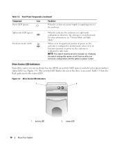
...) When lit, at least one power supply is supplying power to power on enclosure configuration until the system is accessed. Drive Carrier LED Indicators Each drive carrier in your enclosure has two LEDs: an activity LED (green) and a bi-color (green/amber) status LED ...Split Mode." For more information, see Figure 1-3). Figure 1-3. otherwise, the enclosure is in unified mode. The activity LED flashes whenever the drive is power cycled. Split mode LED (green) Enclosure mode switch When lit, indicates the enclosure is in split-mode configuration; Table 1-2. When...
...) When lit, at least one power supply is supplying power to power on enclosure configuration until the system is accessed. Drive Carrier LED Indicators Each drive carrier in your enclosure has two LEDs: an activity LED (green) and a bi-color (green/amber) status LED ...Split Mode." For more information, see Figure 1-3). Figure 1-3. otherwise, the enclosure is in unified mode. The activity LED flashes whenever the drive is power cycled. Split mode LED (green) Enclosure mode switch When lit, indicates the enclosure is in split-mode configuration; Table 1-2. When...

Hardware Owners Manual
Page 11
if only one EMM is being prepared for removal [ms]) Green flashing On 400 ms Off 100 ms Drive rebuilding Amber flashing (125 ms) Drive failed Green/amber flashing Green On 500 ms Amber On 500 ms Off 1000 ms Predicted failure reported by user request or other..., see "Power Supply and Cooling Fan Features." Drive Carrier Status LEDs LED Description Off Slot empty, drive not yet discovered by server, or an unsupported drive is present Steady green Drive is online Green flashing (250 milliseconds Drive is being spun down by drive Green/amber flashing Green On 3000 ms Off 3000...
if only one EMM is being prepared for removal [ms]) Green flashing On 400 ms Off 100 ms Drive rebuilding Amber flashing (125 ms) Drive failed Green/amber flashing Green On 500 ms Amber On 500 ms Off 1000 ms Predicted failure reported by user request or other..., see "Power Supply and Cooling Fan Features." Drive Carrier Status LEDs LED Description Off Slot empty, drive not yet discovered by server, or an unsupported drive is present Steady green Drive is online Green flashing (250 milliseconds Drive is being spun down by drive Green/amber flashing Green On 3000 ms Off 3000...
Hardware Owners Manual
Page 12
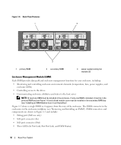
...including: • Monitoring and controlling enclosure environment elements (temperature, fans, power supplies, and enclosure LEDs) • Controlling access to the drives • Communicating enclosure attributes and states to the enclosure via the enclosure midplane (see "Installing an EMM Module Cover in the secondary ...EMM connectors and components are shown in the enclosure. If only one EMM must be installed in Figure 1-5 and include: • Debug port (Dell use only) • SAS port connector (In) • SAS port connector (Out) • Three LEDs (In Port Link, Out Port ...
...including: • Monitoring and controlling enclosure environment elements (temperature, fans, power supplies, and enclosure LEDs) • Controlling access to the drives • Communicating enclosure attributes and states to the enclosure via the enclosure midplane (see "Installing an EMM Module Cover in the secondary ...EMM connectors and components are shown in the enclosure. If only one EMM must be installed in Figure 1-5 and include: • Debug port (Dell use only) • SAS port connector (In) • SAS port connector (Out) • Three LEDs (In Port Link, Out Port ...
Hardware Owners Manual
Page 14
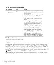
...): Firmware download in the MD1000 host-based RAID solution. Amber flashing (On 250 ms Off 250 ms [twice]; Amber flashing (On 250 ms Off 250 ms [three times]; Amber flashing (On 250 ms Off 250 ms [five times]; Both EMM LEDs will blink. The remaining drives (slots 0-6) are different.... either mode using the enclosure mode switch on the front panel of the enclosure before powering on whether you select the enclosure to eight consecutive drives (slots 7-14) controlled by the secondary (right) EMM. Off 1000 ms): Communication between EMMs are controlled by the primary (left) EMM. ...
...): Firmware download in the MD1000 host-based RAID solution. Amber flashing (On 250 ms Off 250 ms [twice]; Amber flashing (On 250 ms Off 250 ms [three times]; Amber flashing (On 250 ms Off 250 ms [five times]; Both EMM LEDs will blink. The remaining drives (slots 0-6) are different.... either mode using the enclosure mode switch on the front panel of the enclosure before powering on whether you select the enclosure to eight consecutive drives (slots 7-14) controlled by the secondary (right) EMM. Off 1000 ms): Communication between EMMs are controlled by the primary (left) EMM. ...
Hardware Owners Manual
Page 16
... of the primary and secondary EMMs, see "Operating Your Storage Enclosure." When a failed EMM is offered. A failover occurs whenever communication is on power to the drives controlled by the failed EMM.
... of the primary and secondary EMMs, see "Operating Your Storage Enclosure." When a failed EMM is offered. A failover occurs whenever communication is on power to the drives controlled by the failed EMM.
Hardware Owners Manual
Page 20
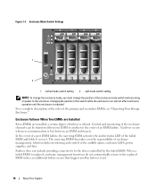
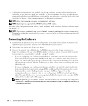
...EMM module of the configuration mode is rebooted. See Figure 2-1 for a cabling diagram of Server Administrator is not supported in the MD1000 host-based RAID solution. Selection of the first enclosure in the daisy chain (see Figure 1-7). NOTE: In split mode, you... Enclosure 1 Confirm that the controller is powered on the storage enclosure (see Figure 2-1). The last enclosure in the chain will control eight drives (slots 7 through 6). For installation instructions and supported operating systems, see your Server Administrator documentation. 2 Turn off the host system and ...
...EMM module of the configuration mode is rebooted. See Figure 2-1 for a cabling diagram of Server Administrator is not supported in the MD1000 host-based RAID solution. Selection of the first enclosure in the daisy chain (see Figure 1-7). NOTE: In split mode, you... Enclosure 1 Confirm that the controller is powered on the storage enclosure (see Figure 2-1). The last enclosure in the chain will control eight drives (slots 7 through 6). For installation instructions and supported operating systems, see your Server Administrator documentation. 2 Turn off the host system and ...
Hardware Owners Manual
Page 27
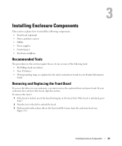
... grounding strap, as explained in the safety instructions found in your Product Information Guide Removing and Replacing the Front Bezel To access the drives in the bezel lock. If the bezel is locked, insert the bezel locking key in your enclosure does not have this bezel, ...skip this section require the use of one or more of the following components: • Front bezel (optional) • Drives and drive carriers • EMMs • Power supplies • Control panel • Enclosure midplane Recommended Tools The procedures in this section. If your enclosure...
... grounding strap, as explained in the safety instructions found in your Product Information Guide Removing and Replacing the Front Bezel To access the drives in the bezel lock. If the bezel is locked, insert the bezel locking key in your enclosure does not have this bezel, ...skip this section require the use of one or more of the following components: • Front bezel (optional) • Drives and drive carriers • EMMs • Power supplies • Control panel • Enclosure midplane Recommended Tools The procedures in this section. If your enclosure...

Hardware Owners Manual
Page 28
... the enclosure. 6 To lock the bezel, insert the key and turn to remove and install drives in its individual drive carrier. NOTICE: Extra care must be damaged by rough handling. Never drop the drives. 30 Installing Enclosure Components Installing and Removing the Front Bezel 1 2 3 1 bezel lock ...precautions, working inside the enclosure. Figure 3-1. The carriers provide some protection, but the drives and carrier connectors can be taken when handling and storing the drives. When removing the drives from the enclosure, place them on the left side of the components inside the ...
... the enclosure. 6 To lock the bezel, insert the key and turn to remove and install drives in its individual drive carrier. NOTICE: Extra care must be damaged by rough handling. Never drop the drives. 30 Installing Enclosure Components Installing and Removing the Front Bezel 1 2 3 1 bezel lock ...precautions, working inside the enclosure. Figure 3-1. The carriers provide some protection, but the drives and carrier connectors can be taken when handling and storing the drives. When removing the drives from the enclosure, place them on the left side of the components inside the ...
Hardware Owners Manual
Page 29
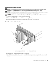
...: Always wear a wrist grounding strap when handling equipment with static-sensitive components. 1 Use Server Administrator to prepare the drive for removal. NOTICE: To avoid data loss when removing a drive, Dell recommends that you use Server Administrator to prepare the drive for more information. Installing Enclosure Components 31 Rotating a carrier handle next to an unseated...
...: Always wear a wrist grounding strap when handling equipment with static-sensitive components. 1 Use Server Administrator to prepare the drive for removal. NOTICE: To avoid data loss when removing a drive, Dell recommends that you use Server Administrator to prepare the drive for more information. Installing Enclosure Components 31 Rotating a carrier handle next to an unseated...

Hardware Owners Manual
Page 30
... Perform the following steps to install the new drive into the carrier: 1 If you are replacing a SAS drive in the carrier, remove the four screws that secure the drive to its carrier and remove the drive (see Figure 3-3). 2 Position the replacement drive into the carrier until it contacts the stop ...tab at the front of the carrier. 4 Secure the drive to the carrier using the four screws removed earlier. NOTICE: Always wear a wrist grounding strap when handling equipment with the drive's controller board facing the carrier shield as shown in the Enclosure NOTICE: To...
... Perform the following steps to install the new drive into the carrier: 1 If you are replacing a SAS drive in the carrier, remove the four screws that secure the drive to its carrier and remove the drive (see Figure 3-3). 2 Position the replacement drive into the carrier until it contacts the stop ...tab at the front of the carrier. 4 Secure the drive to the carrier using the four screws removed earlier. NOTICE: Always wear a wrist grounding strap when handling equipment with the drive's controller board facing the carrier shield as shown in the Enclosure NOTICE: To...


