Hardware Owners Manual
Page 3
... and Cooling Fan Features 17 Enclosure Alarms 18 2 Operating Your Storage Enclosure Before You Begin 19 Cabling Your Enclosure for Unified or Split Mode 19 Connecting the Enclosure 20 Using Your Enclosure to Expand a Dell PowerVault MD3000 Enclosure 21 Changing Your Enclosure's Operating Mode 24 Managing Your Storage Enclosure 25 Downloading Firmware 25...
... and Cooling Fan Features 17 Enclosure Alarms 18 2 Operating Your Storage Enclosure Before You Begin 19 Cabling Your Enclosure for Unified or Split Mode 19 Connecting the Enclosure 20 Using Your Enclosure to Expand a Dell PowerVault MD3000 Enclosure 21 Changing Your Enclosure's Operating Mode 24 Managing Your Storage Enclosure 25 Downloading Firmware 25...

Hardware Owners Manual
Page 13
... more links into the port are not connected. Off: Interface is not active. Figure 1-5. Provide SAS connection for cabling to host or next upchain expansion enclosure (unified mode only). Provide SAS connection for cabling to connect the enclosure using the EMM ports, see "Operating Your Storage Enclosure." Off: Interface is not active... 1 Debug Port 2 SAS Port (In) In 3 In Port Link Status LED (green/amber) 4 SAS Port (Out) Out 5 Out Port Link Status LED (green/amber) Function Dell factory use only. Green: All links into the port are connected.
... more links into the port are not connected. Off: Interface is not active. Figure 1-5. Provide SAS connection for cabling to host or next upchain expansion enclosure (unified mode only). Provide SAS connection for cabling to connect the enclosure using the EMM ports, see "Operating Your Storage Enclosure." Off: Interface is not active... 1 Debug Port 2 SAS Port (In) In 3 In Port Link Status LED (green/amber) 4 SAS Port (Out) Out 5 Out Port Link Status LED (green/amber) Function Dell factory use only. Green: All links into the port are connected.
Hardware Owners Manual
Page 19
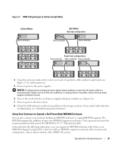
...A unified configuration is one in which your enclosure is connected to one of a unified mode configuration. Product Information Guide (for a cabling diagram of up to three enclosures daisy-chained to a host system for example, a server with your storage enclosure, including: - ...In unified mode, your enclosure can be one host (for either unified or split mode. Operating Your Storage Enclosure 19 SAS interconnect cables - Server Administrator documentation - See Figure 2-1 for important safety, regulatory, and warranty information) - Before You Begin Before connecting your...
...A unified configuration is one in which your enclosure is connected to one of a unified mode configuration. Product Information Guide (for a cabling diagram of up to three enclosures daisy-chained to a host system for example, a server with your storage enclosure, including: - ...In unified mode, your enclosure can be one host (for either unified or split mode. Operating Your Storage Enclosure 19 SAS interconnect cables - Server Administrator documentation - See Figure 2-1 for important safety, regulatory, and warranty information) - Before You Begin Before connecting your...
Hardware Owners Manual
Page 20
... host controller. NOTE: The enclosure mode switch must be set to the mode you can cable the enclosure to the In port on the secondary EMM (see Figure 2-1). See Figure 2-1. Attach subsequent storage enclosures in the MD1000 host-based RAID solution. Changing the configuration selection after the enclosure is powered on has...
... host controller. NOTE: The enclosure mode switch must be set to the mode you can cable the enclosure to the In port on the secondary EMM (see Figure 2-1). See Figure 2-1. Attach subsequent storage enclosures in the MD1000 host-based RAID solution. Changing the configuration selection after the enclosure is powered on has...
Hardware Owners Manual
Page 21
... Enclosure 21 If any amber fault indicators are illuminated, see Figure 1-7 for switch positions). 5 Connect power to two MD1000 expansion enclosures. This expansion increases the maximum physical disk pool of the storage enclosure. The MD3000 supports the addition of operation, either...power supplies. EMM Cabling Diagram in a direct-attach solution with a PERC 5/E system. NOTICE: To safeguard your enclosure behind an MD3000 enclosure to a protected power supply, such as a UPS, line conditioner, or surge protector. Using Your Enclosure to Expand a Dell PowerVault MD3000 Enclosure You ...
... Enclosure 21 If any amber fault indicators are illuminated, see Figure 1-7 for switch positions). 5 Connect power to two MD1000 expansion enclosures. This expansion increases the maximum physical disk pool of the storage enclosure. The MD3000 supports the addition of operation, either...power supplies. EMM Cabling Diagram in a direct-attach solution with a PERC 5/E system. NOTICE: To safeguard your enclosure behind an MD3000 enclosure to a protected power supply, such as a UPS, line conditioner, or surge protector. Using Your Enclosure to Expand a Dell PowerVault MD3000 Enclosure You ...
Hardware Owners Manual
Page 23
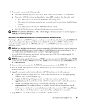
...package. b Upgrade the MD Storage Manager on each host (the latest versions are installed automatically when you must back up all cables between the PERC 5/E and the MD1000 enclosure. 4 Upgrade components on the host(s) and on any attached hosts. 5 Power on the systems in Full or Host ...support.dell.com). On Windows hosts, the drivers are available from A00 to an MD3000 enclosure. c After the MD3000 enclosure is still attached to the PERC 5/E controller, upgrade the EMM firmware to the PowerVault MD3000 Installation Guide for an MD3000 enclosure, the physical disks of the MD1000 ...
...package. b Upgrade the MD Storage Manager on each host (the latest versions are installed automatically when you must back up all cables between the PERC 5/E and the MD1000 enclosure. 4 Upgrade components on the host(s) and on any attached hosts. 5 Power on the systems in Full or Host ...support.dell.com). On Windows hosts, the drivers are available from A00 to an MD3000 enclosure. c After the MD3000 enclosure is still attached to the PERC 5/E controller, upgrade the EMM firmware to the PowerVault MD3000 Installation Guide for an MD3000 enclosure, the physical disks of the MD1000 ...

Hardware Owners Manual
Page 35
... the enclosure) until the module is retracted into the slot and secure. 4 If necessary, update the firmware for the latest information on EMM connections and cabling, see "Downloading Firmware." See the Dell Support website at support.dell.com for your EMM(s).
... the enclosure) until the module is retracted into the slot and secure. 4 If necessary, update the firmware for the latest information on EMM connections and cabling, see "Downloading Firmware." See the Dell Support website at support.dell.com for your EMM(s).
Hardware Owners Manual
Page 37
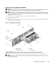
.../cooling fan module is functioning normally, you can remove or replace the other while the enclosure is powered on /off switch. 2 Unplug the AC power cable. 3 Using a Phillips-head screwdriver, loosen the two captive screws securing the power supply/cooling fan module in the remaining module will decrease gradually when a new...
.../cooling fan module is functioning normally, you can remove or replace the other while the enclosure is powered on /off switch. 2 Unplug the AC power cable. 3 Using a Phillips-head screwdriver, loosen the two captive screws securing the power supply/cooling fan module in the remaining module will decrease gradually when a new...
Hardware Owners Manual
Page 38
... front plate is even with the front plate of the bay until you remove it is firmly seated in the bay. 4 Connect the AC power cable to the new power supply and to an electrical outlet. 5 Turn on the on/off switch on /off switch. 3 Tighten the two captive screws to... precautions, working inside the enclosure. It is connected to the backplane and cannot be removed or replaced unless the system is powered on, all power cables to the enclosure. 4 Loosen the two thumbscrews on the front of the system, as well as you connect the AC power...
... front plate is even with the front plate of the bay until you remove it is firmly seated in the bay. 4 Connect the AC power cable to the new power supply and to an electrical outlet. 5 Turn on the on/off switch on /off switch. 3 Tighten the two captive screws to... precautions, working inside the enclosure. It is connected to the backplane and cannot be removed or replaced unless the system is powered on, all power cables to the enclosure. 4 Loosen the two thumbscrews on the front of the system, as well as you connect the AC power...

Hardware Owners Manual
Page 39
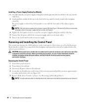
... on a flat, secure surface. 8 Slide the control panel assembly straight out from its connector engages into the rack and tighten the thumbscrews securely. 6 Reconnect power cables to the enclosure and power it back on. 7 Power on the backplane (see Figure 3-8). Installing Enclosure Components 41 Figure 3-8.
... on a flat, secure surface. 8 Slide the control panel assembly straight out from its connector engages into the rack and tighten the thumbscrews securely. 6 Reconnect power cables to the enclosure and power it back on. 7 Power on the backplane (see Figure 3-8). Installing Enclosure Components 41 Figure 3-8.

Hardware Owners Manual
Page 43
... enclosure or EMM while the server is online • Powering down the enclosure while the server is online • Downloading enclosure firmware • Disconnecting the cables to remove the enclosure cover and access any procedure, see "About Your System." and back-panel indicators, see your documentation. Before performing any of beeps...
... enclosure or EMM while the server is online • Powering down the enclosure while the server is online • Downloading enclosure firmware • Disconnecting the cables to remove the enclosure cover and access any procedure, see "About Your System." and back-panel indicators, see your documentation. Before performing any of beeps...

Hardware Owners Manual
Page 44
... Action • Foreign Configuration 1 Enter the Ctrl-R utility 2 Import the foreign configuration (right click "controller" for a drop-down the server. 2 Verify that all storage subsystem cabling between the PERC5/E Adapter and all attached enclosures, including daisy-chained enclosures, is properly connected and secured. 3 Ensure that is lost to any additional user...
... Action • Foreign Configuration 1 Enter the Ctrl-R utility 2 Import the foreign configuration (right click "controller" for a drop-down the server. 2 Verify that all storage subsystem cabling between the PERC5/E Adapter and all attached enclosures, including daisy-chained enclosures, is properly connected and secured. 3 Ensure that is lost to any additional user...

Hardware Owners Manual
Page 45
... electrostatic discharge. 1 Turn off the enclosure and disconnect all power. 2 Remove all external cables are securely attached to remove the enclosure cover and access any procedure, see the Dell PERC5/E Adapter User's Guide. See "Removing and Installing an EMM. Troubleshooting External Connections Loose... or improperly connected cables and bent pins are the most likely source of problems. Ensure that ...
... electrostatic discharge. 1 Turn off the enclosure and disconnect all power. 2 Remove all external cables are securely attached to remove the enclosure cover and access any procedure, see the Dell PERC5/E Adapter User's Guide. See "Removing and Installing an EMM. Troubleshooting External Connections Loose... or improperly connected cables and bent pins are the most likely source of problems. Ensure that ...
Hardware Owners Manual
Page 46
... in the previous steps. 8 Reconnect the enclosure to the enclosure midplane) • Power supply/cooling fan modules • EMMs • Enclosure midplane 2 Ensure that all cables are properly connected and that the following components are lit. 46 Troubleshooting Your Enclosure See "Removing and Installing the Power Supply/Cooling Fan Module." 5 Remove...
... in the previous steps. 8 Reconnect the enclosure to the enclosure midplane) • Power supply/cooling fan modules • EMMs • Enclosure midplane 2 Ensure that all cables are properly connected and that the following components are lit. 46 Troubleshooting Your Enclosure See "Removing and Installing the Power Supply/Cooling Fan Module." 5 Remove...

Hardware Owners Manual
Page 49
... 3 If you selected. If they are not, see "Enclosure Management Module (EMM)." 2 Make sure that all cables are attached correctly according to the enclosure mode you reseated cables, reboot the host server. If the problem persists, refer to "Troubleshooting a Loss of Communication Condition," or see ... the EMM port link status LED and the EMM status LED are solid green for each port that the interposer is connected to a cable. See "Removing and Installing Drives." 3 Inspect the drive and midplane connectors for possible recovery actions. For more information on enclosure modes,...
... 3 If you selected. If they are not, see "Enclosure Management Module (EMM)." 2 Make sure that all cables are attached correctly according to the enclosure mode you reseated cables, reboot the host server. If the problem persists, refer to "Troubleshooting a Loss of Communication Condition," or see ... the EMM port link status LED and the EMM status LED are solid green for each port that the interposer is connected to a cable. See "Removing and Installing Drives." 3 Inspect the drive and midplane connectors for possible recovery actions. For more information on enclosure modes,...

Hardware Owners Manual
Page 53
... customer assistance. Dell Enterprise Training and Certification Dell Enterprise Training and Certification is for credit. 5 Pack the equipment to be offered in the original (or equivalent) packing materials. This service may not be returned in all items being returned (such as power cables, media such as CDs... and diskettes, and guides) if the return is available; You are responsible for insuring any product returned, and you assume the risk of loss during shipment to Dell. For the telephone number to call ....
... customer assistance. Dell Enterprise Training and Certification Dell Enterprise Training and Certification is for credit. 5 Pack the equipment to be offered in the original (or equivalent) packing materials. This service may not be returned in all items being returned (such as power cables, media such as CDs... and diskettes, and guides) if the return is available; You are responsible for insuring any product returned, and you assume the risk of loss during shipment to Dell. For the telephone number to call ....
Hardware Owners Manual
Page 60
... from multiple disks into one logical volume, allowing more processors connected via a high-bandwidth link and managed by changing settings in the cable. The amount of options for operation. system configuration information - A start Windows, it when you change them again. TCP/IP -... RAM, controllers for technical support. spanning - striping - Disk striping writes data across three or more disks in effect until you call Dell for peripherals, and various ROM chips. SVGA - system diskette - System Setup program - A BIOS-based program that allows a network manager...
... from multiple disks into one logical volume, allowing more processors connected via a high-bandwidth link and managed by changing settings in the cable. The amount of options for operation. system configuration information - A start Windows, it when you change them again. TCP/IP -... RAM, controllers for technical support. spanning - striping - Disk striping writes data across three or more disks in effect until you call Dell for peripherals, and various ROM chips. SVGA - system diskette - System Setup program - A BIOS-based program that allows a network manager...

Hardware Owners Manual
Page 61
... a program can be connected and disconnected while the system is a way to create common information formats and to other hubs or switches without requiring a crossover cable. win.ini file - Windows Powered -
... a program can be connected and disconnected while the system is a way to create common information formats and to other hubs or switches without requiring a crossover cable. win.ini file - Windows Powered -

Hardware Owners Manual
Page 63
... cooling fan features, 17 troubleshooting, 48 D damaged systems troubleshooting, 46 Dell contacting, 54 E enclosure managing, 25 enclosure management module, 12 bay cover, 36 installing, 35 removing, 34 enclosure mode cabling, 19 changing, 24 split, 19 unified, 19 F firmware downloading, 25 front bezel removing and replacing, 27 front-panel indicators LED indicators, 9 M... 46 power supply features, 17 R rack-mounted systems installing, 19 H hard drives installing and removing, 30 removing and replacing, 29 S safety, 43 support contacting Dell, 54 system cooling troubleshooting, 47 Index 63
... cooling fan features, 17 troubleshooting, 48 D damaged systems troubleshooting, 46 Dell contacting, 54 E enclosure managing, 25 enclosure management module, 12 bay cover, 36 installing, 35 removing, 34 enclosure mode cabling, 19 changing, 24 split, 19 unified, 19 F firmware downloading, 25 front bezel removing and replacing, 27 front-panel indicators LED indicators, 9 M... 46 power supply features, 17 R rack-mounted systems installing, 19 H hard drives installing and removing, 30 removing and replacing, 29 S safety, 43 support contacting Dell, 54 system cooling troubleshooting, 47 Index 63
Getting Started Guide: (English, Brazilian Portuguese, and Spanish)
Page 8
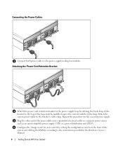
... the top of the loop and the middle clasp to the power supply loop by setting the configuration switch on the front of the power cables into a grounded electrical outlet or a separate power source such as an uninterruptible power supply (UPS) or a power distribution unit (PDU). Attach... the system power cable to the power supply/cooling fan modules. Attaching the Power Cord Retention Bracket Attach the power cord retention bracket to the vertical middle of the...
... the top of the loop and the middle clasp to the power supply loop by setting the configuration switch on the front of the power cables into a grounded electrical outlet or a separate power source such as an uninterruptible power supply (UPS) or a power distribution unit (PDU). Attach... the system power cable to the power supply/cooling fan modules. Attaching the Power Cord Retention Bracket Attach the power cord retention bracket to the vertical middle of the...


