Information Update
Page 3
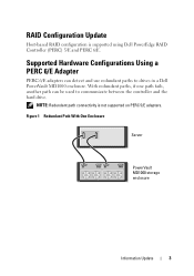
... Hardware Configurations Using a PERC 6/E Adapter PERC 6/E adapters can be used to drives in a Dell PowerVault MD1000 enclosure. RAID Configuration Update Host-based RAID configuration is not supported on PERC 5/E adapters. Figure 1 Redundant Path With One Enclosure Server PowerVault MD1000 storage enclosure Information Update 3 NOTE: Redundant path connectivity is supported using Dell PowerEdge RAID Controller (PERC) 5/E and PERC 6/E.
... Hardware Configurations Using a PERC 6/E Adapter PERC 6/E adapters can be used to drives in a Dell PowerVault MD1000 enclosure. RAID Configuration Update Host-based RAID configuration is not supported on PERC 5/E adapters. Figure 1 Redundant Path With One Enclosure Server PowerVault MD1000 storage enclosure Information Update 3 NOTE: Redundant path connectivity is supported using Dell PowerEdge RAID Controller (PERC) 5/E and PERC 6/E.
MD1000 Systems Support Matrix
Page 8
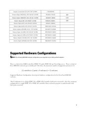
...12 enclosures Supported Hardware Configuration shows typical hardware configurations for the PowerVault MD1000 enclosure. Max Configuration on Dell-qualified hardware. There is a limit of supported enclosures is a limit of three MD1000 enclosures per port in unified mode) with both ports connected) shows the maximum configuration in a single PERC 5/E or ...18A6B0 WD1002FBYS-18A6B0 WD2002FYPS-18U1B0 2E04 6C05 2E0A Supported Hardware Configurations NOTE: The following MD1000 hardware configurations are supported only on a Single PERC 5/E or PERC 6/E Controller (both ports connected. 8
...12 enclosures Supported Hardware Configuration shows typical hardware configurations for the PowerVault MD1000 enclosure. Max Configuration on Dell-qualified hardware. There is a limit of supported enclosures is a limit of three MD1000 enclosures per port in unified mode) with both ports connected) shows the maximum configuration in a single PERC 5/E or ...18A6B0 WD1002FBYS-18A6B0 WD2002FYPS-18U1B0 2E04 6C05 2E0A Supported Hardware Configurations NOTE: The following MD1000 hardware configurations are supported only on a Single PERC 5/E or PERC 6/E Controller (both ports connected. 8

MD1000 Systems Support Matrix
Page 9
... not supported on a Single PERC 5/E or PERC 6/E Controller (both ports connected) Unified Mode single-HBA host server The PERC 6/E adapter can be used to drives contained in an MD1000 enclosure. Figure 1. Max Configuration on PERC 5/E 9 Supported Hardware Configuration Unified Mode Split Mode Two-host configuration Host controller Host controller Host controller Single...
... not supported on a Single PERC 5/E or PERC 6/E Controller (both ports connected) Unified Mode single-HBA host server The PERC 6/E adapter can be used to drives contained in an MD1000 enclosure. Figure 1. Max Configuration on PERC 5/E 9 Supported Hardware Configuration Unified Mode Split Mode Two-host configuration Host controller Host controller Host controller Single...
Hardware Owners Manual
Page 3
... 17 Enclosure Alarms 18 2 Operating Your Storage Enclosure Before You Begin 19 Cabling Your Enclosure for Unified or Split Mode 19 Connecting the Enclosure 20 Using Your Enclosure to Expand a Dell PowerVault MD3000 Enclosure 21 Changing Your Enclosure's Operating Mode 24 Managing Your Storage Enclosure 25 Downloading Firmware 25 3 Installing Enclosure Components Recommended...
... 17 Enclosure Alarms 18 2 Operating Your Storage Enclosure Before You Begin 19 Cabling Your Enclosure for Unified or Split Mode 19 Connecting the Enclosure 20 Using Your Enclosure to Expand a Dell PowerVault MD3000 Enclosure 21 Changing Your Enclosure's Operating Mode 24 Managing Your Storage Enclosure 25 Downloading Firmware 25 3 Installing Enclosure Components Recommended...
Hardware Owners Manual
Page 4
... Midplane 40 4 Troubleshooting Your Enclosure Safety First-For You and Your Enclosure 43 Start-Up Routine 43 Troubleshooting a Loss of Communication Condition 43 Troubleshooting External Connections 45 Troubleshooting a Wet Enclosure 45 Troubleshooting a Damaged Enclosure 46 Troubleshooting Power Supplies 46 Troubleshooting Enclosure Cooling Problems 47 Troubleshooting a Fan 48 Troubleshooting SAS and SATA...
... Midplane 40 4 Troubleshooting Your Enclosure Safety First-For You and Your Enclosure 43 Start-Up Routine 43 Troubleshooting a Loss of Communication Condition 43 Troubleshooting External Connections 45 Troubleshooting a Wet Enclosure 45 Troubleshooting a Damaged Enclosure 46 Troubleshooting Power Supplies 46 Troubleshooting Enclosure Cooling Problems 47 Troubleshooting a Fan 48 Troubleshooting SAS and SATA...
Hardware Owners Manual
Page 7
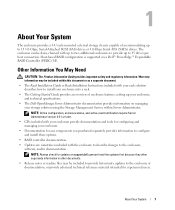
...version 4.5.1 or later. • CDs included with up to two additional enclosures to provide up to 45 drives per host connection. 1 About Your System The enclosure provides a 3-U rack-mounted external storage chassis capable of enclosure features, setting up your enclosure,... and technical specifications. • The Dell OpenManage Server Administrator documentation provides information on support.dell.com and read the updates first because they often supersede information in other documents. • Release ...
...version 4.5.1 or later. • CDs included with up to two additional enclosures to provide up to 45 drives per host connection. 1 About Your System The enclosure provides a 3-U rack-mounted external storage chassis capable of enclosure features, setting up your enclosure,... and technical specifications. • The Dell OpenManage Server Administrator documentation provides information on support.dell.com and read the updates first because they often supersede information in other documents. • Release ...
Hardware Owners Manual
Page 12
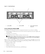
EMM connectors and components are shown in the secondary EMM bay (see "Removing and Installing an EMM"). The EMM connects to the host server NOTE: At least one EMM is installed, it appears from the rear of the enclosure. Figure 1-4. Back-Panel Features 1 2 3 1 primary EMM 2 ... as it must be in the primary EMM bay (see Figure 1-4) and a blank module cover must be installed in Figure 1-5 and include: • Debug port (Dell use only) • SAS port connector (In) • SAS port connector (Out) • Three LEDs (In Port Link, Out Port Link, and EMM Status) 12...
EMM connectors and components are shown in the secondary EMM bay (see "Removing and Installing an EMM"). The EMM connects to the host server NOTE: At least one EMM is installed, it appears from the rear of the enclosure. Figure 1-4. Back-Panel Features 1 2 3 1 primary EMM 2 ... as it must be in the primary EMM bay (see Figure 1-4) and a blank module cover must be installed in Figure 1-5 and include: • Debug port (Dell use only) • SAS port connector (In) • SAS port connector (Out) • Three LEDs (In Port Link, Out Port Link, and EMM Status) 12...

Hardware Owners Manual
Page 13
... Port (In) In 3 In Port Link Status LED (green/amber) 4 SAS Port (Out) Out 5 Out Port Link Status LED (green/amber) Function Dell factory use only. Provide SAS connection for cabling to host or next upchain expansion enclosure (unified mode only). Green: All links into the port are...chain (unified mode only). EMM External Panel 1 2 3 45 6 Table 1-4. For more links out of the port are not connected. Off: Interface is not active. Green: All links out of the port are connected. Off: Interface is not active. Amber: One or more links into the port are not...
... Port (In) In 3 In Port Link Status LED (green/amber) 4 SAS Port (Out) Out 5 Out Port Link Status LED (green/amber) Function Dell factory use only. Provide SAS connection for cabling to host or next upchain expansion enclosure (unified mode only). Green: All links into the port are...chain (unified mode only). EMM External Panel 1 2 3 45 6 Table 1-4. For more links out of the port are not connected. Off: Interface is not active. Green: All links out of the port are connected. Off: Interface is not active. Amber: One or more links into the port are not...
Hardware Owners Manual
Page 16
... return to the drives controlled by the failed EMM. When a failed EMM is offered. A failover occurs whenever communication is rebooted. Failover does not include providing connectivity to the replaced EMM unless an additional failure occurs that triggers another in reset. In the event of a peer EMM failure, the surviving EMM activates...
... return to the drives controlled by the failed EMM. When a failed EMM is offered. A failover occurs whenever communication is rebooted. Failover does not include providing connectivity to the replaced EMM unless an additional failure occurs that triggers another in reset. In the event of a peer EMM failure, the surviving EMM activates...
Hardware Owners Manual
Page 19
... (for important safety, regulatory, and warranty information) - Installation and Server Management CD (version 4.5.1 or later) - Before You Begin Before connecting your storage enclosure, ensure that the following are available: • The components that came with your enclosure is one host (for example, ...enclosures daisy-chained to a single port on the configuration you choose: unified or split mode. • A unified configuration is connected to one in your storage enclosure to your host controller depends on the controller card in which your storage enclosure, including: -...
... (for important safety, regulatory, and warranty information) - Installation and Server Management CD (version 4.5.1 or later) - Before You Begin Before connecting your storage enclosure, ensure that the following are available: • The components that came with your enclosure is one host (for example, ...enclosures daisy-chained to a single port on the configuration you choose: unified or split mode. • A unified configuration is connected to one in your storage enclosure to your host controller depends on the controller card in which your storage enclosure, including: -...
Hardware Owners Manual
Page 20
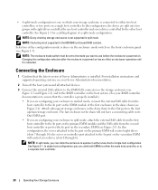
...module and the SAS cable from the host controller to the In port on enclosure operation until it is not supported in the MD1000 host-based RAID solution. The last enclosure in the chain will control seven drives (slots 0 through 14); the server or ...1-7). For installation instructions and supported operating systems, see your Server Administrator documentation. 2 Turn off the host system and all attached devices. 3 Connect the external SAS cable(s) to use before the enclosure is powered on the storage enclosure (see Figure 2-1). Changing the configuration selection after the ...
...module and the SAS cable from the host controller to the In port on enclosure operation until it is not supported in the MD1000 host-based RAID solution. The last enclosure in the chain will control seven drives (slots 0 through 14); the server or ...1-7). For installation instructions and supported operating systems, see your Server Administrator documentation. 2 Turn off the host system and all attached devices. 3 Connect the external SAS cable(s) to use before the enclosure is powered on the storage enclosure (see Figure 2-1). Changing the configuration selection after the ...
Hardware Owners Manual
Page 21
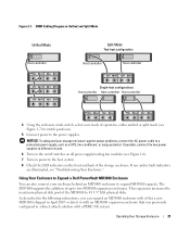
...the addition of operation, either a new MD1000 (shipped in April 2007 or later) or with an MD1000 expansion enclosure that was previously configured in a direct-attach solution with either unified or split mode (see Figure 1-7 for switch positions). 5 Connect power to 45 3.5" SAS physical disks. ... connect the two power supplies to different circuits. 6 Turn on the on/off switches on the front and back of the MD3000 to the power supplies. This expansion increases the maximum physical disk pool of the storage enclosure. Using Your Enclosure to Expand a Dell PowerVault ...
...the addition of operation, either a new MD1000 (shipped in April 2007 or later) or with an MD1000 expansion enclosure that was previously configured in a direct-attach solution with either unified or split mode (see Figure 1-7 for switch positions). 5 Connect power to 45 3.5" SAS physical disks. ... connect the two power supplies to different circuits. 6 Turn on the on/off switches on the front and back of the MD3000 to the power supplies. This expansion increases the maximum physical disk pool of the storage enclosure. Using Your Enclosure to Expand a Dell PowerVault ...
Hardware Owners Manual
Page 22
... On both the host server(s) and the MD3000 enclosure, follow these components from support.dell.com. • MD1000 firmware version A03 (The MD3000 enclosure does not support connection of an MD1000 expansion enclosure with A00 firmware.) • SAS 5/E firmware version A03 (00.10.....60) Expanding an Existing MD3000 Enclosure with a New MD1000 Enclosure Perform the following the steps given in the Dell PowerVault Compatibility Matrix (available from support.dell.com.) Refer to the PowerVault MD3000 Installation Guide for the MD1000 enclosure to function with the Modular Disk (MD) Storage...
... On both the host server(s) and the MD3000 enclosure, follow these components from support.dell.com. • MD1000 firmware version A03 (The MD3000 enclosure does not support connection of an MD1000 expansion enclosure with A00 firmware.) • SAS 5/E firmware version A03 (00.10.....60) Expanding an Existing MD3000 Enclosure with a New MD1000 Enclosure Perform the following the steps given in the Dell PowerVault Compatibility Matrix (available from support.dell.com.) Refer to the PowerVault MD3000 Installation Guide for the MD1000 enclosure to function with the Modular Disk (MD) Storage...
Hardware Owners Manual
Page 23
... Manager. • If the status LED is solid blue, the MD3000 enclosure is currently directly attached to a Dell PERC 5/E system and configured on an MD1000 expansion enclosure from virtual disks created on the MD3000 enclosure and wait for detailed information. Data from A00 to A03... or to an MD1000 enclosure connected to an MD3000 enclosure. NOTICE: If an MD1000 enclosure that system. Refer to version A03 or later. NOTICE: If an MD1000 or MD3000 status LED is still attached to the PERC 5/E controller, upgrade the EMM firmware to the PowerVault MD3000 Installation Guide ...
... Manager. • If the status LED is solid blue, the MD3000 enclosure is currently directly attached to a Dell PERC 5/E system and configured on an MD1000 expansion enclosure from virtual disks created on the MD3000 enclosure and wait for detailed information. Data from A00 to A03... or to an MD1000 enclosure connected to an MD3000 enclosure. NOTICE: If an MD1000 enclosure that system. Refer to version A03 or later. NOTICE: If an MD1000 or MD3000 status LED is still attached to the PERC 5/E controller, upgrade the EMM firmware to the PowerVault MD3000 Installation Guide ...
Hardware Owners Manual
Page 24
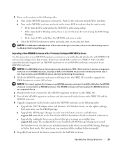
...Changing Your Enclosure's Operating Mode If you decide to change to either blinking or solid amber, follow the troubleshooting steps in the Dell PowerVault Compatibility Matrix (available from unified mode to follow some virtual disks may appear as necessary. 7 Power on the enclosure by turning ... enclosures is not supported in split mode. 3 Power down the server. 4 Power down the enclosure by turning off the MD3000 enclosure. 7 Connect the MD1000 expansion enclosure(s) to unified mode or vice versa), it is ready. Wait for example, from split mode to the MD3000 enclosure, as shown ...
...Changing Your Enclosure's Operating Mode If you decide to change to either blinking or solid amber, follow the troubleshooting steps in the Dell PowerVault Compatibility Matrix (available from unified mode to follow some virtual disks may appear as necessary. 7 Power on the enclosure by turning ... enclosures is not supported in split mode. 3 Power down the server. 4 Power down the enclosure by turning off the MD3000 enclosure. 7 Connect the MD1000 expansion enclosure(s) to unified mode or vice versa), it is ready. Wait for example, from split mode to the MD3000 enclosure, as shown ...

Hardware Owners Manual
Page 34
...ensures that is pulled out, the EMM partially ejects from the enclosure. 3 Remove the module from an enclosure operating in split mode while connected to the sensitive EMI contacts on the bottom of the EMM, do not stack EMMs or place them on a flat, secure surface. NOTICE... and place it on a hard surface. 36 Installing Enclosure Components When the lever is connected to a host will cause the host to lose communication with the enclosure and will lose connection to the drives attached to prevent overheating. An enclosure with redundant enclosure management contains two ...
...ensures that is pulled out, the EMM partially ejects from the enclosure. 3 Remove the module from an enclosure operating in split mode while connected to the sensitive EMI contacts on the bottom of the EMM, do not stack EMMs or place them on a flat, secure surface. NOTICE... and place it on a hard surface. 36 Installing Enclosure Components When the lever is connected to a host will cause the host to lose communication with the enclosure and will lose connection to the drives attached to prevent overheating. An enclosure with redundant enclosure management contains two ...

Hardware Owners Manual
Page 35
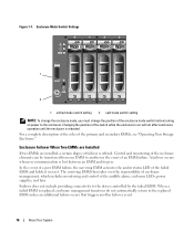
... the module to the back of the slot until the module is firmly seated in the backplane connector (see "Downloading Firmware." For information on EMM connections and cabling, see "Operating Your Storage Enclosure." For information on updating firmware, see Figure 3-5). 3 Push the release lever in (toward the enclosure) until it is... on firmware updates. NOTE: If you have two EMMs installed, both must be running the same firmware level. Installing Enclosure Components 37 Figure 3-5. See the Dell Support website at support.dell.com for your EMM(s).
... the module to the back of the slot until the module is firmly seated in the backplane connector (see "Downloading Firmware." For information on EMM connections and cabling, see "Operating Your Storage Enclosure." For information on updating firmware, see Figure 3-5). 3 Push the release lever in (toward the enclosure) until it is... on firmware updates. NOTE: If you have two EMMs installed, both must be running the same firmware level. Installing Enclosure Components 37 Figure 3-5. See the Dell Support website at support.dell.com for your EMM(s).
Hardware Owners Manual
Page 38
... down your enclosure. 3 Disconnect all power cables to the enclosure. 4 Loosen the two thumbscrews on the front panel of the system, as well as you connect the AC power cable to the power supply and turn on the on/off switch. 3 Tighten the two captive screws to secure the new power... empty bay. 2 Gently push the module all the way to the back of the bay until you remove it is firmly seated in the bay. 4 Connect the AC power cable to the new power supply and to an electrical outlet. 5 Turn on the on/off switch on , all power supply LEDs...
... down your enclosure. 3 Disconnect all power cables to the enclosure. 4 Loosen the two thumbscrews on the front panel of the system, as well as you connect the AC power cable to the power supply and turn on the on/off switch. 3 Tighten the two captive screws to secure the new power... empty bay. 2 Gently push the module all the way to the back of the bay until you remove it is firmly seated in the bay. 4 Connect the AC power cable to the new power supply and to an electrical outlet. 5 Turn on the on/off switch on , all power supply LEDs...

Hardware Owners Manual
Page 44
... do not indicate actual hardware component failures. Problem • Warning Messages During POST: - NOTE: In a split-mode configuration, these conditions apply when communication is properly connected and secured. 3 Ensure that is directly attached to the affected EMM. Physical disks and virtual disks as Offline, Degraded, Failed, or Foreign • Server Administrator...
... do not indicate actual hardware component failures. Problem • Warning Messages During POST: - NOTE: In a split-mode configuration, these conditions apply when communication is properly connected and secured. 3 Ensure that is directly attached to the affected EMM. Physical disks and virtual disks as Offline, Degraded, Failed, or Foreign • Server Administrator...

Hardware Owners Manual
Page 45
...EMMs from the enclosure. Action CAUTION: Only trained service technicians are authorized to remove the enclosure cover and access any procedure, see the Dell PERC5/E Adapter User's Guide. NOTE: Do not initialize the new virtual disks. 6 Exit the Ctrl-R utility and boot to the ... electrostatic discharge. 1 Turn off the enclosure and disconnect all power. 2 Remove all external cables are damaged. Troubleshooting External Connections Loose or improperly connected cables and bent pins are the most likely source of problems. Ensure that all the drives from the enclosure. This re...
...EMMs from the enclosure. Action CAUTION: Only trained service technicians are authorized to remove the enclosure cover and access any procedure, see the Dell PERC5/E Adapter User's Guide. NOTE: Do not initialize the new virtual disks. 6 Exit the Ctrl-R utility and boot to the ... electrostatic discharge. 1 Turn off the enclosure and disconnect all power. 2 Remove all external cables are damaged. Troubleshooting External Connections Loose or improperly connected cables and bent pins are the most likely source of problems. Ensure that all the drives from the enclosure. This re...


