
Reference and Installation Guide (.pdf)
Page 2
... names other than its own. Intel, Pentium and LANDesk are registered trademarks and DellWare is a registered trademark of Microsoft Corporation; As an Energy Star Partner, Dell Computer Corporation has determined that this text: Dell, OptiPlex, and the DELL logo are registered trademarks and MMX is a trademark of Video Electronics Standards Association. October 1997 P/N 88700...
... names other than its own. Intel, Pentium and LANDesk are registered trademarks and DellWare is a registered trademark of Microsoft Corporation; As an Energy Star Partner, Dell Computer Corporation has determined that this text: Dell, OptiPlex, and the DELL logo are registered trademarks and MMX is a trademark of Video Electronics Standards Association. October 1997 P/N 88700...

Reference and Installation Guide (.pdf)
Page 3
... vents. Special shelves are not located where they can cause fire or electric shock by shorting out interior components. • Keep your computer away from Dell and other v When Using Your Computer System As you work. Doing so can be sure your monitor and attached peripherals are electrically rated to operate...
... vents. Special shelves are not located where they can cause fire or electric shock by shorting out interior components. • Keep your computer away from Dell and other v When Using Your Computer System As you work. Doing so can be sure your monitor and attached peripherals are electrically rated to operate...

Reference and Installation Guide (.pdf)
Page 4
monitor screen at or below eye level wrists relaxed and flat monitor and keyboard positioned directly in front of time. When you stop typing, try to 24 inches] from your eyes). • Make sure the monitor screen is on your feet and not on the floor vi sources) to help you correctly position your keyboard. • Set the monitor at a comfortable viewing distance (usually 510 to 610 millimeters [20 to do not have to rest your hands while using the keyboard or mouse. • Always leave space to type for extended periods of user arms at your sides. • Sit erect, with ...
monitor screen at or below eye level wrists relaxed and flat monitor and keyboard positioned directly in front of time. When you stop typing, try to 24 inches] from your eyes). • Make sure the monitor screen is on your feet and not on the floor vi sources) to help you correctly position your keyboard. • Set the monitor at a comfortable viewing distance (usually 510 to 610 millimeters [20 to do not have to rest your hands while using the keyboard or mouse. • Always leave space to type for extended periods of user arms at your sides. • Sit erect, with ...

Reference and Installation Guide (.pdf)
Page 5
... appear throughout this document to remind you continue to work , periodically touch an unpainted metal surface on the computer chassis to install the component in Dell documentation. Hold a component such as a microprocessor chip by its edges, not by its pins. As you of these safety guidelines when appropriate: • When you...
... appear throughout this document to remind you continue to work , periodically touch an unpainted metal surface on the computer chassis to install the component in Dell documentation. Hold a component such as a microprocessor chip by its edges, not by its pins. As you of these safety guidelines when appropriate: • When you...

Reference and Installation Guide (.pdf)
Page 7
... and Chapter 7, "Installing Drives," are intended for users who want to new in which regulatory agencies have tested and approved the Dell OptiPlex Gn or Gn+ low-profile systems. • Appendix D, "Warranties and Return Policy," describes the warranty for users who are summarized as reference material... for users interested in learning more about the Dell warranty for anyone who want to connect their system to upgrade their system or who uses a Dell OptiPlex Gn or Gn+ low-profile computer system. For information about the details of Chapter ...
... and Chapter 7, "Installing Drives," are intended for users who want to new in which regulatory agencies have tested and approved the Dell OptiPlex Gn or Gn+ low-profile systems. • Appendix D, "Warranties and Return Policy," describes the warranty for users who are summarized as reference material... for users interested in learning more about the Dell warranty for anyone who want to connect their system to upgrade their system or who uses a Dell OptiPlex Gn or Gn+ low-profile computer system. For information about the details of Chapter ...
Reference and Installation Guide (.pdf)
Page 8
... are included in this document: • Keycaps, the labeling that helps you need to configure and install these updates before calling Dell for technical assistance. • The Diagnostics and Troubleshooting Guide includes troubleshooting procedures and instructions for attaching devices to avoid the problem. ...system. This document includes descriptions of text printed in bold type within boxes or in lowercase bold are often asked by Dell computer users. You may be installed on your computer system. Always read these cards before consulting any options you ordered...
... are included in this document: • Keycaps, the labeling that helps you need to configure and install these updates before calling Dell for technical assistance. • The Diagnostics and Troubleshooting Guide includes troubleshooting procedures and instructions for attaching devices to avoid the problem. ...system. This document includes descriptions of text printed in bold type within boxes or in lowercase bold are often asked by Dell computer users. You may be installed on your computer system. Always read these cards before consulting any options you ordered...

Reference and Installation Guide (.pdf)
Page 9
Command lines are displayed in lowercase bold. constant parameters are presented in lowercase bold; They are displayed in the Courier New font. Examples: autoexec.bat and c:\windows • Syntax lines consist of the command's possible parameters. It can be a system message, for example, or it can be text that you substitute a value) are displayed in italics. Example: del [drive:] [path] filename [/p] • Command lines consist of a command and may include one or more of a command and all its possible parameters. Screen text is text that are instructed to as a ...
Command lines are displayed in lowercase bold. constant parameters are presented in lowercase bold; They are displayed in the Courier New font. Examples: autoexec.bat and c:\windows • Syntax lines consist of the command's possible parameters. It can be a system message, for example, or it can be text that you substitute a value) are displayed in italics. Example: del [drive:] [path] filename [/p] • Command lines consist of a command and may include one or more of a command and all its possible parameters. Screen text is text that are instructed to as a ...
Reference and Installation Guide (.pdf)
Page 11
Contents Chapter 1 Introduction 1-1 System Features 1-1 Using the Power Switch 1-4 Using the Optional Floor Stand 1-4 Security Cable Slot and Padlock Ring 1-5 Energy Star Compliance 1-6 Important Notes to Windows 95 Users 1-6 Reinstalling Windows 95 1-6 Intel PIIX4 INF Update Installer for Windows 95 1-7 Accessing Online Documentation 1-7 Getting Help 1-7 Chapter 2 Using the System Setup Program 2-1 Entering the System Setup Program 2-1 System Setup Screens 2-1 Using the System Setup Program 2-2 System Setup Categories 2-4 Time 2-4 Date 2-4 Diskette Drive A and Diskette Drive...
Contents Chapter 1 Introduction 1-1 System Features 1-1 Using the Power Switch 1-4 Using the Optional Floor Stand 1-4 Security Cable Slot and Padlock Ring 1-5 Energy Star Compliance 1-6 Important Notes to Windows 95 Users 1-6 Reinstalling Windows 95 1-6 Intel PIIX4 INF Update Installer for Windows 95 1-7 Accessing Online Documentation 1-7 Getting Help 1-7 Chapter 2 Using the System Setup Program 2-1 Entering the System Setup Program 2-1 System Setup Screens 2-1 Using the System Setup Program 2-2 System Setup Categories 2-4 Time 2-4 Date 2-4 Diskette Drive A and Diskette Drive...

Reference and Installation Guide (.pdf)
Page 12
Password Status 2-6 Boot Sequence 2-7 Diskette First 2-7 Hard Disk Only 2-7 CD-ROM First 2-7 Device List 2-7 Setup Password 2-9 Auto Power On 2-9 Power Management 2-9 Saving Monitor Power 2-9 Saving EIDE Hard-Disk Drive Power 2-10 Wakeup On LAN 2-10 NIC 2-10 Mouse 2-10 Serial Port 1 and Serial Port 2 2-10 Parallel Port 2-11 Parallel Mode 2-11 IDE Hard Disk 2-11 Diskette 2-11 Speaker 2-11 System Data Categories 2-12 Using the System Password Feature 2-12 Assigning a System Password 2-12 Using Your System Password to Secure Your System 2-13 Deleting or Changing an ...
Password Status 2-6 Boot Sequence 2-7 Diskette First 2-7 Hard Disk Only 2-7 CD-ROM First 2-7 Device List 2-7 Setup Password 2-9 Auto Power On 2-9 Power Management 2-9 Saving Monitor Power 2-9 Saving EIDE Hard-Disk Drive Power 2-10 Wakeup On LAN 2-10 NIC 2-10 Mouse 2-10 Serial Port 1 and Serial Port 2 2-10 Parallel Port 2-11 Parallel Mode 2-11 IDE Hard Disk 2-11 Diskette 2-11 Speaker 2-11 System Data Categories 2-12 Using the System Password Feature 2-12 Assigning a System Password 2-12 Using Your System Password to Secure Your System 2-13 Deleting or Changing an ...
Reference and Installation Guide (.pdf)
Page 13
Preparing to Use the ICU 3-3 Backing Up the ICU Diskette 3-3 Starting the ICU 3-3 Accessing Help 3-3 Making Selections in the ICU 3-3 Adding a Listed Card 3-4 Adding an Unlisted Card 3-6 Modifying a Card 3-7 Removing a Card 3-8 Viewing Resources 3-8 Saving the System Configuration 3-9 Exiting From the ICU 3-9 Locking and Unlocking Cards 3-9 Locking and Unlocking All Resources 3-9 Locking and Unlocking Configuration Resources 3-10 Chapter 4 Using Integrated Devices 4-1 Video Controller 4-1 Network Interface Controller 4-1 Network Cable Requirements 4-2 Configuring the NIC ...
Preparing to Use the ICU 3-3 Backing Up the ICU Diskette 3-3 Starting the ICU 3-3 Accessing Help 3-3 Making Selections in the ICU 3-3 Adding a Listed Card 3-4 Adding an Unlisted Card 3-6 Modifying a Card 3-7 Removing a Card 3-8 Viewing Resources 3-8 Saving the System Configuration 3-9 Exiting From the ICU 3-9 Locking and Unlocking Cards 3-9 Locking and Unlocking All Resources 3-9 Locking and Unlocking Configuration Resources 3-10 Chapter 4 Using Integrated Devices 4-1 Video Controller 4-1 Network Interface Controller 4-1 Network Cable Requirements 4-2 Configuring the NIC ...
Reference and Installation Guide (.pdf)
Page 14
Inside Your Computer 5-4 Jumpers 5-4 System Board Labels 5-8 Chapter 6 Installing System Board Options 6-1 Expansion Cards 6-2 Expansion Slots 6-2 Installing an Expansion Card 6-2 Removing an Expansion Card 6-4 Adding Memory 6-4 Performing a Memory Upgrade 6-5 Installing a DIMM 6-6 Removing a DIMM 6-6 Upgrading the Microprocessor 6-6 Replacing the System Battery 6-9 Chapter 7 Installing Drives 7-1 Removing and Replacing Front-Panel Inserts 7-1 EIDE Drive Addressing 7-2 Connecting Drives 7-3 Installing a Drive in the 5.25-Inch Drive Bay 7-3 Installing an EIDE Hard-Disk Drive...
Inside Your Computer 5-4 Jumpers 5-4 System Board Labels 5-8 Chapter 6 Installing System Board Options 6-1 Expansion Cards 6-2 Expansion Slots 6-2 Installing an Expansion Card 6-2 Removing an Expansion Card 6-4 Adding Memory 6-4 Performing a Memory Upgrade 6-5 Installing a DIMM 6-6 Removing a DIMM 6-6 Upgrading the Microprocessor 6-6 Replacing the System Battery 6-9 Chapter 7 Installing Drives 7-1 Removing and Replacing Front-Panel Inserts 7-1 EIDE Drive Addressing 7-2 Connecting Drives 7-3 Installing a Drive in the 5.25-Inch Drive Bay 7-3 Installing an EIDE Hard-Disk Drive...

Reference and Installation Guide (.pdf)
Page 15
... 1-4. and Canada Only D-1 Coverage During Year One D-1 Coverage During Years Two and Three D-2 General D-2 "Total Satisfaction" Return Policy (U.S. Figure 2-1. Figure 1-3. Appendix C Regulatory Notices C-1 FCC Notices (U.S. Dell Inspector Program 1-4 Attaching the Optional Floor Stand 1-5 Security Cable Slot and Padlock Ring 1-5 Energy Star Emblem 1-6 System Setup Screens 2-3 Sample Device List Screen 2-8 ICU Window...
... 1-4. and Canada Only D-1 Coverage During Year One D-1 Coverage During Years Two and Three D-2 General D-2 "Total Satisfaction" Return Policy (U.S. Figure 2-1. Figure 1-3. Appendix C Regulatory Notices C-1 FCC Notices (U.S. Dell Inspector Program 1-4 Attaching the Optional Floor Stand 1-5 Security Cable Slot and Padlock Ring 1-5 Energy Star Emblem 1-6 System Setup Screens 2-3 Sample Device List Screen 2-8 ICU Window...

Reference and Installation Guide (.pdf)
Page 16
Figure 3-11. Figure 5-5. Figure 6-3. Figure 6-10. Figure 6-14. Figure 7-5. Figure 3-6. Figure 3-10. Figure 5-6. Figure 6-6. Figure 6-9. Figure 7-3. Figure 7-6. Figure 3-7. Figure 3-8. Figure 4-1. Figure 5-2. Figure 6-8. Figure 6-12. Figure 7-2. Figure 3-5. Figure 5-4. Figure 5-7. Figure 6-2. Figure 7-4. Figure 6-5. Figure 6-13. Figure 7-7. Figure 5-1. Figure 6-11. Figure 7-1. Figure 3-3. Figure 6-1. Add Network Card Dialog Box 3-4 Card Configuration Dialog Box 3-5 Configuration Settings Dialog Box 3-5 Configuration Choice List Box 3-5 Options ...
Figure 3-11. Figure 5-5. Figure 6-3. Figure 6-10. Figure 6-14. Figure 7-5. Figure 3-6. Figure 3-10. Figure 5-6. Figure 6-6. Figure 6-9. Figure 7-3. Figure 7-6. Figure 3-7. Figure 3-8. Figure 4-1. Figure 5-2. Figure 6-8. Figure 6-12. Figure 7-2. Figure 3-5. Figure 5-4. Figure 5-7. Figure 6-2. Figure 7-4. Figure 6-5. Figure 6-13. Figure 7-7. Figure 5-1. Figure 6-11. Figure 7-1. Figure 3-3. Figure 6-1. Add Network Card Dialog Box 3-4 Card Configuration Dialog Box 3-5 Configuration Settings Dialog Box 3-5 Configuration Choice List Box 3-5 Options ...

Reference and Installation Guide (.pdf)
Page 17
Figure 7-11. Table 5-1. Table B-1. Installing a Drive in the 5.25-Inch Drive Bracket 7-5 Inserting the Drive Bracket into the Drive Bay 7-5 Attaching Cables to a Drive in the 5.25-Inch Drive Bay 7-6 Removing the Hard-Disk Drive Bracket 7-7 Securing the Hard-Disk Drive to the Bracket 7-8 Attaching Hard-Disk Drive Cables 7-8 Tables Table 2-1. Table 6-1. Figure 7-12. Table 2-3. Figure 7-8. Table 3-1. Table A-1. Table B-2. Table 2-2. Figure 7-13. Figure 7-9. Figure 7-10. Table 5-2. System-Setup Navigation Keys 2-2 Device-List Screen Navigation Keys 2-7 ...
Figure 7-11. Table 5-1. Table B-1. Installing a Drive in the 5.25-Inch Drive Bracket 7-5 Inserting the Drive Bracket into the Drive Bay 7-5 Attaching Cables to a Drive in the 5.25-Inch Drive Bay 7-6 Removing the Hard-Disk Drive Bracket 7-7 Securing the Hard-Disk Drive to the Bracket 7-8 Attaching Hard-Disk Drive Cables 7-8 Tables Table 2-1. Table 6-1. Figure 7-12. Table 2-3. Figure 7-8. Table 3-1. Table A-1. Table B-2. Table 2-2. Figure 7-13. Figure 7-9. Figure 7-10. Table 5-2. System-Setup Navigation Keys 2-2 Device-List Screen Navigation Keys 2-7 ...
Reference and Installation Guide (.pdf)
Page 19
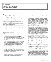
All hard-disk drives shipped with OptiPlex Gn or Gn+ systems are high-speed, expandable personal computers designed around Intel® Pentium® microprocessors. These systems also support the Industry-Standard Architecture (ISA...megabyte (MB) by storing the most recently accessed contents of system memory. • System memory that supports both parity and non- Chapter 1 Introduction Dell® OptiPlex® Gn and Gn+ low-profile systems are SMART-compliant. • Full compliance with PCI specification 2.1. • Full Plug and Play version 1.0a capability, which greatly...
All hard-disk drives shipped with OptiPlex Gn or Gn+ systems are high-speed, expandable personal computers designed around Intel® Pentium® microprocessors. These systems also support the Industry-Standard Architecture (ISA...megabyte (MB) by storing the most recently accessed contents of system memory. • System memory that supports both parity and non- Chapter 1 Introduction Dell® OptiPlex® Gn and Gn+ low-profile systems are SMART-compliant. • Full compliance with PCI specification 2.1. • Full Plug and Play version 1.0a capability, which greatly...

Reference and Installation Guide (.pdf)
Page 20
...Video drivers for several operating sys- port. Maximum resolutions are 1280 x 1024 pixels with 256 colors noninterlaced and 1024 x 768 pixels with Dell OptiPlex Gn+ systems (which supports a 3.5-inch diskette drive and, optionally, a second diskette drive or tape drive. • Enhanced integrated drive electronics...sec. • Two high-performance serial ports and one 16-bit ISA expansion slot on these utilities, see 1-2 Dell OptiPlex Gn and Gn+ Low-Profile Systems Reference and Installation Guide directional parallel port for your online System User's Guide. • Network device...
...Video drivers for several operating sys- port. Maximum resolutions are 1280 x 1024 pixels with 256 colors noninterlaced and 1024 x 768 pixels with Dell OptiPlex Gn+ systems (which supports a 3.5-inch diskette drive and, optionally, a second diskette drive or tape drive. • Enhanced integrated drive electronics...sec. • Two high-performance serial ports and one 16-bit ISA expansion slot on these utilities, see 1-2 Dell OptiPlex Gn and Gn+ Low-Profile Systems Reference and Installation Guide directional parallel port for your online System User's Guide. • Network device...

Reference and Installation Guide (.pdf)
Page 21
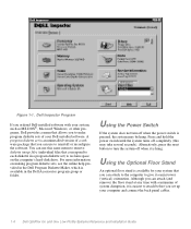
...and Troubleshooting Guide. • Desktop Management Interface (DMI) support, which is in client and administrator versions. If your system has a Dell-installed Microsoft Windows ® , Windows for technical assistance or if you how to configure non-Plug and Play ISA expansion cards manually....After resources have been assigned to these cards, the system BIOS can reduce the energy consumption of your computer system. The Dell Inspector program is already installed on using the diagnostics, see Chapter 3, "Using the ISA Configuration Utility," or your online System User's ...
...and Troubleshooting Guide. • Desktop Management Interface (DMI) support, which is in client and administrator versions. If your system has a Dell-installed Microsoft Windows ® , Windows for technical assistance or if you how to configure non-Plug and Play ISA expansion cards manually....After resources have been assigned to these cards, the system BIOS can reduce the energy consumption of your computer system. The Dell Inspector program is already installed on using the diagnostics, see Chapter 3, "Using the ISA Configuration Utility," or your online System User's ...
Reference and Installation Guide (.pdf)
Page 22
... For more information on making program diskette sets, see the online help provided in the Dell Program Diskette Maker, which is available for your computer and connect the back panel cables. 1-4 Dell OptiPlex Gn and Gn+ Low-Profile Systems Reference and Installation Guide Alternatively, press the reset button to turn off... the software. You can attach to the computer to give it is easiest to attach before you to each diskette in the Dell Accessories program group or folder. Using the Optional Floor Stand An optional floor stand is available in a program diskette set up ...
... For more information on making program diskette sets, see the online help provided in the Dell Program Diskette Maker, which is available for your computer and connect the back panel cables. 1-4 Dell OptiPlex Gn and Gn+ Low-Profile Systems Reference and Installation Guide Alternatively, press the reset button to turn off... the software. You can attach to the computer to give it is easiest to attach before you to each diskette in the Dell Accessories program group or folder. Using the Optional Floor Stand An optional floor stand is available in a program diskette set up ...

Reference and Installation Guide (.pdf)
Page 23
Align the large round locator hole in the floor stand with the securing button on your computer, and lock the device with the screw hole in the cover. captive screw locator hole locator pin (on the back of your computer. The padlock ring allows you lower the stand into place, make sure it will work with the cable slot on the side of the hole pattern as shown in the stand with the key provided. When the stand is at the top. Position the floor stand as shown. To prevent unauthorized removal of your computer, loop the cable around an immovable object, insert the ...
Align the large round locator hole in the floor stand with the securing button on your computer, and lock the device with the screw hole in the cover. captive screw locator hole locator pin (on the back of your computer. The padlock ring allows you lower the stand into place, make sure it will work with the cable slot on the side of the hole pattern as shown in the stand with the key provided. When the stand is at the top. Position the floor stand as shown. To prevent unauthorized removal of your computer, loop the cable around an immovable object, insert the ...
Reference and Installation Guide (.pdf)
Page 24
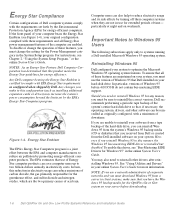
...the two primary causes of the system's entire hard-disk drive so that this product meets the Energy Star guidelines for the OptiPlex Gn or Gn+ system on weekends. TM Figure 1-4. Computer users can reinstall Windows 95 from a server to reinstall your software from a ...you have the Windows 95 backup media for energy efficiency. Energy Star Compliance Certain configurations of Windows 95 before downloading. 1-6 Dell OptiPlex Gn and Gn+ Low-Profile Systems Reference and Installation Guide To ensure that you need to reinstall other software can reduce emissions of carbon dioxide...
...the two primary causes of the system's entire hard-disk drive so that this product meets the Energy Star guidelines for the OptiPlex Gn or Gn+ system on weekends. TM Figure 1-4. Computer users can reinstall Windows 95 from a server to reinstall your software from a ...you have the Windows 95 backup media for energy efficiency. Energy Star Compliance Certain configurations of Windows 95 before downloading. 1-6 Dell OptiPlex Gn and Gn+ Low-Profile Systems Reference and Installation Guide To ensure that you need to reinstall other software can reduce emissions of carbon dioxide...
