Owner's Manual (Desktop)
Page 3
......6 2 Removing and Installing Components 7 Recommended Tools...7 Removing The Cover...7 Installing The Cover...7 Removing The Intrusion Switch...8 Installing The Intrusion Switch...9 Removing The Front Bezel...9 Installing The Front Bezel...10 Removing The Expansion Card...10 Installing The Expansion Card...11 Memory Module Guidelines...11 Removing The Memory...12 Installing The Memory...12 Removing...
......6 2 Removing and Installing Components 7 Recommended Tools...7 Removing The Cover...7 Installing The Cover...7 Removing The Intrusion Switch...8 Installing The Intrusion Switch...9 Removing The Front Bezel...9 Installing The Front Bezel...10 Removing The Expansion Card...10 Installing The Expansion Card...11 Memory Module Guidelines...11 Removing The Memory...12 Installing The Memory...12 Removing...
Owner's Manual (Desktop)
Page 9
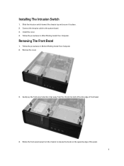
Follow the procedures in Before Working Inside Your Computer. 2. Follow the procedures in After Working Inside Your Computer . Connect the intrusion cable to place. 2. Remove the cover. 3. Gently pry the front panel retention clips away from the chassis to release the hooks on the opposite edge of front bezel. 4. Removing The Front Bezel 1. Install the cover. 4. Installing The Intrusion Switch 1. Slide the intrusion switch toward the chassis top and secure it to the system board. 3. Rotate the front panel away from the chassis located at the side edge of the panel. 9
Follow the procedures in Before Working Inside Your Computer. 2. Follow the procedures in After Working Inside Your Computer . Connect the intrusion cable to place. 2. Remove the cover. 3. Gently pry the front panel retention clips away from the chassis to release the hooks on the opposite edge of front bezel. 4. Removing The Front Bezel 1. Install the cover. 4. Installing The Intrusion Switch 1. Slide the intrusion switch toward the chassis top and secure it to the system board. 3. Rotate the front panel away from the chassis located at the side edge of the panel. 9

Owner's Manual (Desktop)
Page 10
Insert the hooks along the bottom edge of the front panel into place. 3. Follow the procedures in Before Working Inside Your Computer. 2. Removing The Expansion Card 1. Follow the procedures in After Working Inside Your Computer. Install the cover. 4. Lift the release tab on the chassis. 2. Installing The Front Bezel 1. Rotate the bezel toward the computer to engage the four front panel retention clips until they click into the slots on the card-retention latch upward. 10 Remove the cover. 3.
Insert the hooks along the bottom edge of the front panel into place. 3. Follow the procedures in Before Working Inside Your Computer. 2. Removing The Expansion Card 1. Follow the procedures in After Working Inside Your Computer. Install the cover. 4. Lift the release tab on the chassis. 2. Installing The Front Bezel 1. Rotate the bezel toward the computer to engage the four front panel retention clips until they click into the slots on the card-retention latch upward. 10 Remove the cover. 3.
Owner's Manual (Desktop)
Page 15
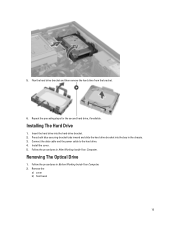
.... 2. Connect the data cable and the power cable to the hard drive. 4. 5. Follow the procedures in After Working Inside Your Computer. Remove the a) cover b) front bezel 15 Repeat the preceding steps for the second hard drive, if available.
.... 2. Connect the data cable and the power cable to the hard drive. 4. 5. Follow the procedures in After Working Inside Your Computer. Remove the a) cover b) front bezel 15 Repeat the preceding steps for the second hard drive, if available.

Owner's Manual (Desktop)
Page 17
Connect the data cable and the power cable to the optical drive. 3. Disconnect the speaker and unthread it. 17 Removing The Speaker 1. Follow the procedures in After Working Inside Your Computer. Install the front bezel. 4. Remove the cover. 3. Installing The Optical Drive 1. Install the cover. 5. Follow the procedures in Before Working Inside Your Computer. 2. Push the optical drive from the front towards the back of the computer. 2.
Connect the data cable and the power cable to the optical drive. 3. Disconnect the speaker and unthread it. 17 Removing The Speaker 1. Follow the procedures in After Working Inside Your Computer. Install the front bezel. 4. Remove the cover. 3. Installing The Optical Drive 1. Install the cover. 5. Follow the procedures in Before Working Inside Your Computer. 2. Push the optical drive from the front towards the back of the computer. 2.

Owner's Manual (Desktop)
Page 25
... triangle mark on the processor should align with the retention hook. 4. Removing The System Fan 1. Ensure the processor is properly seated. Remove the a) cover b) front bezel c) optical drive d) hard drive 3. Gently lower the processor cover. 3. Install the cover. 6. Insert the processor into the processor socket. Installing The Processor 1. Follow the procedures...
... triangle mark on the processor should align with the retention hook. 4. Removing The System Fan 1. Ensure the processor is properly seated. Remove the a) cover b) front bezel c) optical drive d) hard drive 3. Gently lower the processor cover. 3. Install the cover. 6. Insert the processor into the processor socket. Installing The Processor 1. Follow the procedures...

Owner's Manual (Desktop)
Page 28
... the power cables to secure in Before Working Inside Your Computer. 2. Connect the 24-pin connector. 7. Remove the a) cover b) front bezel c) hard drive 28 Pass the four grommets through the chassis and slide outward along the groove to the chassis clips. 6. Thread the system... fan connector cables to the system board. 5. Install the front bezel. 10. Removing The Thermal Sensor 1. Install the hard drive. 8. Follow the procedures in the chassis. 2. Follow the procedures in place. 3. Install...
... the power cables to secure in Before Working Inside Your Computer. 2. Connect the 24-pin connector. 7. Remove the a) cover b) front bezel c) hard drive 28 Pass the four grommets through the chassis and slide outward along the groove to the chassis clips. 6. Thread the system... fan connector cables to the system board. 5. Install the front bezel. 10. Removing The Thermal Sensor 1. Install the hard drive. 8. Follow the procedures in the chassis. 2. Follow the procedures in place. 3. Install...

Owner's Manual (Desktop)
Page 30
Secure the thermal sensor to the system board. 4. Install the front bezel. 6. Installing The Front Thermal Sensor 1. Follow the procedures in and lift to release the power-switch cable from the system board. 30 Press in Before Working Inside Your Computer. 2. Install the hard drive. 5. Install the cover. 7. Thread the thermal-sensor cable into the chassis clips. 3. Connect the thermal-sensor cable to the chassis front. 2. Follow the procedures in After Working Inside Your Computer. Removing The Power Switch 1. Remove the a) cover b) front bezel 3.
Secure the thermal sensor to the system board. 4. Install the front bezel. 6. Installing The Front Thermal Sensor 1. Follow the procedures in and lift to release the power-switch cable from the system board. 30 Press in Before Working Inside Your Computer. 2. Install the hard drive. 5. Install the cover. 7. Thread the thermal-sensor cable into the chassis clips. 3. Connect the thermal-sensor cable to the chassis front. 2. Follow the procedures in After Working Inside Your Computer. Removing The Power Switch 1. Remove the a) cover b) front bezel 3.

Owner's Manual (Desktop)
Page 32
Remove the a) cover b) front bezel c) hard drive d) optical drive 3. Install the cover. 6. Removing The Input/Output Panel 1. Install the front bezel. 5. Secure the power-switch cable to the system board. 4. Follow the procedures in through the front of the computer. 2. Connect the power-switch cable to the chassis. 3. Disconnect the 24-pin connector from the system board. 32 Slide the power-switch cable in Before Working Inside Your Computer. 2. Installing The Power Switch 1. Follow the procedures in After Working Inside Your Computer.
Remove the a) cover b) front bezel c) hard drive d) optical drive 3. Install the cover. 6. Removing The Input/Output Panel 1. Install the front bezel. 5. Secure the power-switch cable to the system board. 4. Follow the procedures in through the front of the computer. 2. Connect the power-switch cable to the chassis. 3. Disconnect the 24-pin connector from the system board. 32 Slide the power-switch cable in Before Working Inside Your Computer. 2. Installing The Power Switch 1. Follow the procedures in After Working Inside Your Computer.

Owner's Manual (Desktop)
Page 34
...of the computer to the chassis. 3. Install the optical drive. 7. Follow the procedures in Before Working Inside Your Computer. 2. Remove the a) cover b) front bezel c) expansion card d) memory e) heat sink f) processor 3. Install the cover. 10. Disconnect all the cables connected to the chassis. 4. Tighten the screw ... to the system board. 34 Connect the Input/Output Board/FlyWire cable to the system board. 6. Install the front bezel. 9. Follow the procedures in After Working Inside Your Computer. Removing The System Board 1. 7. Installing The Input/Output Panel 1.
...of the computer to the chassis. 3. Install the optical drive. 7. Follow the procedures in Before Working Inside Your Computer. 2. Remove the a) cover b) front bezel c) expansion card d) memory e) heat sink f) processor 3. Install the cover. 10. Disconnect all the cables connected to the chassis. 4. Tighten the screw ... to the system board. 34 Connect the Input/Output Board/FlyWire cable to the system board. 6. Install the front bezel. 9. Follow the procedures in After Working Inside Your Computer. Removing The System Board 1. 7. Installing The Input/Output Panel 1.
Owner's Manual (Desktop)
Page 37
19. RTC reset jumper (RTCRST) Installing The System Board 1. Tighten the screws securing the system board to the system board. 4. Install the processor. 5. Install the front bezel. 9. Follow the procedures in the chassis. 2. Install the cover. 10. Password Jumper (PSWD) 21. Connect all the cables to the chassis. 3. Install the memory. 7. Install the heat sink. 6. Install the expansion card. 8. Internal USB Connector (INT_USB) 20. Align the system board to the port connectors and place the system board in After Working Inside Your Computer. 37
19. RTC reset jumper (RTCRST) Installing The System Board 1. Tighten the screws securing the system board to the system board. 4. Install the processor. 5. Install the front bezel. 9. Follow the procedures in the chassis. 2. Install the cover. 10. Password Jumper (PSWD) 21. Connect all the cables to the chassis. 3. Install the memory. 7. Install the heat sink. 6. Install the expansion card. 8. Internal USB Connector (INT_USB) 20. Align the system board to the port connectors and place the system board in After Working Inside Your Computer. 37

Owner's Manual (Mini-Tower)
Page 3
......6 2 Removing and Installing Components 7 Recommended Tools...7 Removing the Cover...7 Installing the Cover...7 Removing the Intrusion Switch...8 Installing the Intrusion Switch...9 Removing the Front Bezel...9 Installing the Front Bezel...10 Removing the Expansion Cards...10 Installing the Expansion Card...12 Memory Module Guidelines...12 Removing the Memory...12 Installing the Memory...13 Removing...
......6 2 Removing and Installing Components 7 Recommended Tools...7 Removing the Cover...7 Installing the Cover...7 Removing the Intrusion Switch...8 Installing the Intrusion Switch...9 Removing the Front Bezel...9 Installing the Front Bezel...10 Removing the Expansion Cards...10 Installing the Expansion Card...12 Memory Module Guidelines...12 Removing the Memory...12 Installing the Memory...13 Removing...

Owner's Manual (Mini-Tower)
Page 9
Gently pry the front panel retention clips away from the chassis located at the edge of front panel. 9 Removing the Front Bezel 1. Follow the procedures in After Working Inside Your Computer. Follow the procedures in Before Working Inside Your Computer. 2. Remove the cover. 3. Install the cover. 4. Connect the intrusion cable to secure it towards the top to the system board. 3. Installing the Intrusion Switch 1. Insert the intrusion switch into its place in the chassis rear and slide it . 2.
Gently pry the front panel retention clips away from the chassis located at the edge of front panel. 9 Removing the Front Bezel 1. Follow the procedures in After Working Inside Your Computer. Follow the procedures in Before Working Inside Your Computer. 2. Remove the cover. 3. Install the cover. 4. Connect the intrusion cable to secure it towards the top to the system board. 3. Installing the Intrusion Switch 1. Insert the intrusion switch into its place in the chassis rear and slide it . 2.

Owner's Manual (Mini-Tower)
Page 10
Rotate the bezel toward the computer to release the hooks on the chassis front. 2. Follow the procedures in After Working Inside Your Computer. Insert the hooks along the bottom edge of the panel from the chassis. Install the cover. 4. Removing the Expansion Cards 1. Follow the procedures in Before Working Inside Your Computer. 2. 4. Remove the cover. 10 Installing the Front Bezel 1. Rotate the front panel away from the computer to engage the front-panel retention clips until they click into the slots on the opposite edge of the front panel into place. 3.
Rotate the bezel toward the computer to release the hooks on the chassis front. 2. Follow the procedures in After Working Inside Your Computer. Insert the hooks along the bottom edge of the panel from the chassis. Install the cover. 4. Removing the Expansion Cards 1. Follow the procedures in Before Working Inside Your Computer. 2. 4. Remove the cover. 10 Installing the Front Bezel 1. Rotate the front panel away from the computer to engage the front-panel retention clips until they click into the slots on the opposite edge of the front panel into place. 3.

Owner's Manual (Mini-Tower)
Page 27
b) front bezel c) optical drive 3. Press in to release it from the chassis and pull the power switch out of the computer. 27 Release the power-switch cable from the system board. 4. Press the clips on both side of the power switch to release and remove the power-switch cable from the chassis clips. 5.
b) front bezel c) optical drive 3. Press in to release it from the chassis and pull the power switch out of the computer. 27 Release the power-switch cable from the system board. 4. Press the clips on both side of the power switch to release and remove the power-switch cable from the chassis clips. 5.

Owner's Manual (Small Form Factor)
Page 3
... Off Your Computer...6 After Working Inside Your Computer...6 2 Removing and Installing Components 7 Recommended Tools...7 Removing the Cover...7 Installing the Cover...7 Removing the Front Bezel...8 Installing the Front Bezel...8 Removing the Drive Cage...9 Installing the Drive Cage...10 Removing the Optical Drive...10 Installing the Optical Drive...12 Removing the Hard Drive...12...
... Off Your Computer...6 After Working Inside Your Computer...6 2 Removing and Installing Components 7 Recommended Tools...7 Removing the Cover...7 Installing the Cover...7 Removing the Front Bezel...8 Installing the Front Bezel...8 Removing the Drive Cage...9 Installing the Drive Cage...10 Removing the Optical Drive...10 Installing the Optical Drive...12 Removing the Hard Drive...12...

Owner's Manual (Small Form Factor)
Page 8
... from the chassis. Insert the hooks along the bottom edge of the bezel from the computer to engage the front bezel retention clips until they click into the slots on the opposite edge of the front bezel into place. 3. Follow the procedures in Before Working Inside Your Computer. ...2. Remove the cover. 3. Installing the Front Bezel 1. Follow the procedures in After Working Inside Your Computer. 8 Push the bezel toward the computer to release the hooks on the chassis front. 2. Pry the front bezel retention clips away from the computer. Then, lift the chassis ...
... from the chassis. Insert the hooks along the bottom edge of the bezel from the computer to engage the front bezel retention clips until they click into the slots on the opposite edge of the front bezel into place. 3. Follow the procedures in Before Working Inside Your Computer. ...2. Remove the cover. 3. Installing the Front Bezel 1. Follow the procedures in After Working Inside Your Computer. 8 Push the bezel toward the computer to release the hooks on the chassis front. 2. Pry the front bezel retention clips away from the computer. Then, lift the chassis ...

Owner's Manual (Small Form Factor)
Page 9
Remove the data cable and power cable from the back of the computer into the unlocked position. 9 Follow the procedures in Before Working Inside Your Computer. 2. Slide the drive-cage handle toward the back of the drive. 4. Remove the: a) cover b) front bezel 3. Removing the Drive Cage 1.
Remove the data cable and power cable from the back of the computer into the unlocked position. 9 Follow the procedures in Before Working Inside Your Computer. 2. Slide the drive-cage handle toward the back of the drive. 4. Remove the: a) cover b) front bezel 3. Removing the Drive Cage 1.

Owner's Manual (Small Form Factor)
Page 10
... into the chassis. Follow the procedures in the chassis. 4. Removing the Optical Drive 1. Follow the procedures in Before Working Inside Your Computer. 2. Install the: a) front bezel b) cover 7. 5.
... into the chassis. Follow the procedures in the chassis. 4. Removing the Optical Drive 1. Follow the procedures in Before Working Inside Your Computer. 2. Install the: a) front bezel b) cover 7. 5.

Owner's Manual (Small Form Factor)
Page 15
... are mixed with single or dual-rank modules, the quad-rank modules must be labelled differently depending on the hardware configuration. Remove the: a) cover b) front bezel c) drive cage 3. Follow the procedures in After Working Inside Your Computer. Connect the intrusion-switch cable to secure it outward to the system board. 3. NOTE...
... are mixed with single or dual-rank modules, the quad-rank modules must be labelled differently depending on the hardware configuration. Remove the: a) cover b) front bezel c) drive cage 3. Follow the procedures in After Working Inside Your Computer. Connect the intrusion-switch cable to secure it outward to the system board. 3. NOTE...


