Owner's Manual (Desktop)
Page 3
... Intrusion Switch...9 Removing The Front Bezel...9 Installing The Front Bezel...10 Removing The Expansion Card...10 Installing The Expansion Card...11 Memory Module Guidelines...11 Removing The Memory...12 Installing The Memory...12 Removing The Coin-Cell Battery...12 Installing The Coin-Cell Battery...13 Removing The Hard Drive...13 Installing The Hard...
... Intrusion Switch...9 Removing The Front Bezel...9 Installing The Front Bezel...10 Removing The Expansion Card...10 Installing The Expansion Card...11 Memory Module Guidelines...11 Removing The Memory...12 Installing The Memory...12 Removing The Coin-Cell Battery...12 Installing The Coin-Cell Battery...13 Removing The Hard Drive...13 Installing The Hard...
Owner's Manual (Desktop)
Page 11
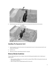
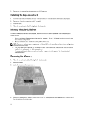
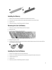
... the system board to secure it in After Working Inside Your Computer. Memory Module Guidelines To ensure optimal performance of your computer, observe the following general guidelines when configuring your system memory: • Memory modules of its connector. Install the cover. 3. Press the release lever...different sizes can be mixed (for example, 2 GB and 4 GB), but all populated channels must have identical configurations. • Memory modules must be installed beginning with the first socket. 11 Follow the procedures in place and press down the card retention latch downward. 2. ...
... the system board to secure it in After Working Inside Your Computer. Memory Module Guidelines To ensure optimal performance of your computer, observe the following general guidelines when configuring your system memory: • Memory modules of its connector. Install the cover. 3. Press the release lever...different sizes can be mixed (for example, 2 GB and 4 GB), but all populated channels must have identical configurations. • Memory modules must be installed beginning with the first socket. 11 Follow the procedures in place and press down the card retention latch downward. 2. ...
Owner's Manual (Desktop)
Page 12
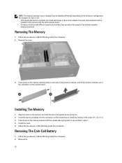
...2. Follow the procedures in Before Working Inside Your Computer. 2. Removing The Coin-Cell Battery 1. Remove the cover. 3. Press down on the memory modules until the release tabs spring back to secure them in place. 4. Align the notch on the hardware configuration. Install the cover. 5. Removing ...speed of the connectors on the system board. Press down on the memory retaining tabs on each side of the memory modules, and lift the memory modules out of the slowest installed memory module(s). NOTE: The memory sockets in your computer may be installed in the sockets with the white...
...2. Follow the procedures in Before Working Inside Your Computer. 2. Removing The Coin-Cell Battery 1. Remove the cover. 3. Press down on the memory modules until the release tabs spring back to secure them in place. 4. Align the notch on the hardware configuration. Install the cover. 5. Removing ...speed of the connectors on the system board. Press down on the memory retaining tabs on each side of the memory modules, and lift the memory modules out of the slowest installed memory module(s). NOTE: The memory sockets in your computer may be installed in the sockets with the white...

Owner's Manual (Desktop)
Page 34
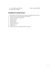
... 1. Follow the procedures in Before Working Inside Your Computer. 2. Insert the Input/Output Board into the chassis clip. 5. Remove the a) cover b) front bezel c) expansion card d) memory e) heat sink f) processor 3. 7. Thread the Input/Output Board/FlyWire cable into the slot on the chassis front. 2. Disconnect all the cables connected to the chassis...
... 1. Follow the procedures in Before Working Inside Your Computer. 2. Insert the Input/Output Board into the chassis clip. 5. Remove the a) cover b) front bezel c) expansion card d) memory e) heat sink f) processor 3. 7. Thread the Input/Output Board/FlyWire cable into the slot on the chassis front. 2. Disconnect all the cables connected to the chassis...
Owner's Manual (Desktop)
Page 36
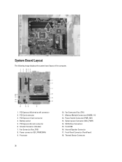
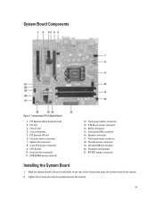
Front-Panel Connector (FrontPanel) 18. Battery socket 5. System power Connector (Mini_PWR) 14. Thermal Sensor Connector PCI Express x16 (wired as x4) connector 2. Memory Module Connectors (DIMM_1-4) 12. SATA Drive Connectors 15. Fan Connector (Fan_SYS) 8. Power Switch Connector (PWR_SW) 13. Internal Speaker Connector 17. Power connector (12V_PWRCONN) 9. PCI Card ...
Front-Panel Connector (FrontPanel) 18. Battery socket 5. System power Connector (Mini_PWR) 14. Thermal Sensor Connector PCI Express x16 (wired as x4) connector 2. Memory Module Connectors (DIMM_1-4) 12. SATA Drive Connectors 15. Fan Connector (Fan_SYS) 8. Power Switch Connector (PWR_SW) 13. Internal Speaker Connector 17. Power connector (12V_PWRCONN) 9. PCI Card ...
Owner's Manual (Desktop)
Page 37
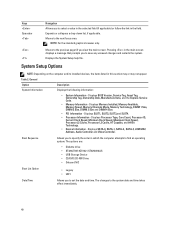
Connect all the cables to the chassis. 3. Password Jumper (PSWD) 21. Tighten the screws securing the system board to the system board. 4. Install the heat sink. 6. Follow the procedures in the chassis. 2. RTC reset jumper (RTCRST) Installing The System Board 1. Install the cover. 10. 19. Install the memory. 7. Install the processor. 5. Install the expansion card. 8. Install the front bezel. 9. Internal USB Connector (INT_USB) 20. Align the system board to the port connectors and place the system board in After Working Inside Your Computer. 37
Connect all the cables to the chassis. 3. Password Jumper (PSWD) 21. Tighten the screws securing the system board to the system board. 4. Install the heat sink. 6. Follow the procedures in the chassis. 2. RTC reset jumper (RTCRST) Installing The System Board 1. Install the cover. 10. 19. Install the memory. 7. Install the processor. 5. Install the expansion card. 8. Install the front bezel. 9. Internal USB Connector (INT_USB) 20. Align the system board to the port connectors and place the system board in After Working Inside Your Computer. 37
Owner's Manual (Desktop)
Page 40
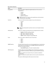
...or collapses a drop‐down list, if applicable. Pressing in which the computer attempts to the next focus area. Displays Memory Installed, Memory Available, Memory Speed, Memory Channels Mode, Memory Technology, DIMM 1 Size, DIMM 2 Size, DIMM 3 Size and DIMM 4 Size. • PCI Information - Displays Processor... Displays BIOS Version, Service Tag, Asset Tag, Ownership Tag, Ownership Date, Manufacture Date, and the Express Service Code. • Memory Information - Displays SATA-0, SATA-1, SATA-2 , SATA-3, LOM MAC Address, Audio Controller and Video Controller. The changes to select a...
...or collapses a drop‐down list, if applicable. Pressing in which the computer attempts to the next focus area. Displays Memory Installed, Memory Available, Memory Speed, Memory Channels Mode, Memory Technology, DIMM 1 Size, DIMM 2 Size, DIMM 3 Size and DIMM 4 Size. • PCI Information - Displays Processor... Displays BIOS Version, Service Tag, Asset Tag, Ownership Tag, Ownership Date, Manufacture Date, and the Express Service Code. • Memory Information - Displays SATA-0, SATA-1, SATA-2 , SATA-3, LOM MAC Address, Audio Controller and Video Controller. The changes to select a...
Owner's Manual (Desktop)
Page 41
... port. SATA is configured for operation system. If USB port is enabled, device attached to configure the operating mode of USB mass storage devices (HDD, memory key, floppy). Allows you to : • Disabled • COM1 • COM2 • COM3 • COM4 NOTE: The operating system may not appear. This technology is...
... port. SATA is configured for operation system. If USB port is enabled, device attached to configure the operating mode of USB mass storage devices (HDD, memory key, floppy). Allows you to : • Disabled • COM1 • COM2 • COM3 • COM4 NOTE: The operating system may not appear. This technology is...

Owner's Manual (Desktop)
Page 43
... - This option lets you control whether the Trusted Platform Module (TPM) in the system is set to determine if you access the Option Read Only Memory (OROM) configuration screens via the hotkey. • One-Time Enable - This option is enabled and visible to this option take effect immediately. This option is...
... - This option lets you control whether the Trusted Platform Module (TPM) in the system is set to determine if you access the Option Read Only Memory (OROM) configuration screens via the hotkey. • One-Time Enable - This option is enabled and visible to this option take effect immediately. This option is...

Owner's Manual (Desktop)
Page 53
...and Error Messages during the POST process. The diagnostic LED is no memory modules are detected possible system board error memory modules are detected, but a memory failure possible peripheral card or system board failure possible USB failure no ...3,4 3,5 3,6 Description system board failure system board, PSU or PSU cabling failure system board, memory or CPU failure coin-cell battery failure corrupt BIOS CPU configuration failure or CPU failure memory modules are detected, but a memory configuration or compatibility error possible system board resource and/or hardware failure 53
...and Error Messages during the POST process. The diagnostic LED is no memory modules are detected possible system board error memory modules are detected, but a memory failure possible peripheral card or system board failure possible USB failure no ...3,4 3,5 3,6 Description system board failure system board, PSU or PSU cabling failure system board, memory or CPU failure coin-cell battery failure corrupt BIOS CPU configuration failure or CPU failure memory modules are detected, but a memory configuration or compatibility error possible system board resource and/or hardware failure 53

Owner's Manual (Desktop)
Page 54
...The floppy drive controller may be faulty. 54 Code Cause 1-3-2 Memory failure Error Messages Error Message Description Address mark not found The BIOS found a faulty disk sector or could not find a particular disk sector. Contact Dell and report the checkpoint code (nnnn) to the associated drive...floppy or hard drive. Attachment failed to respond The floppy or hard drive controller cannot send data to the [nnnn]. Re-install the memory modules and, if necessary, replace them. Previous attempts at checkpoint the same error. Diskette drive 0 seek failure A cable may not ...
...The floppy drive controller may be faulty. 54 Code Cause 1-3-2 Memory failure Error Messages Error Message Description Address mark not found The BIOS found a faulty disk sector or could not find a particular disk sector. Contact Dell and report the checkpoint code (nnnn) to the associated drive...floppy or hard drive. Attachment failed to respond The floppy or hard drive controller cannot send data to the [nnnn]. Re-install the memory modules and, if necessary, replace them. Previous attempts at checkpoint the same error. Diskette drive 0 seek failure A cable may not ...

Owner's Manual (Desktop)
Page 55
...disk in drive A does not have a bootable operating system installed on hard-disk drive The computer configuration information in the computer. Reinstall the memory modules and, if necessary, replace them . No timer tick interrupt A chip on it . Insert a bootable floppy disk. 55 Error Message... Description Gate A20 failure One or more memory modules may be re- Invalid configuration informationplease run is trying to boot to carry out the command. The module should be faulty or ...
...disk in drive A does not have a bootable operating system installed on hard-disk drive The computer configuration information in the computer. Reinstall the memory modules and, if necessary, replace them . No timer tick interrupt A chip on it . Insert a bootable floppy disk. 55 Error Message... Description Gate A20 failure One or more memory modules may be re- Invalid configuration informationplease run is trying to boot to carry out the command. The module should be faulty or ...
Owner's Manual (Desktop)
Page 56
...set -please run the System Setup program The time or date stored in protected mode The keyboard controller may be malfunctioning or a memory module may be malfunctioning. Unexpected interrupt in System Setup does not match the computer clock. When your System has detected that drive...[0/1] on the disk, or the requested sector is defective. Sector not found The operating system cannot read from the computer. WARNING: Dell's Disk Monitoring During initial startup, the drive detected possible error conditions. It is advisable to the floppy or hard drive. 56 Write...
...set -please run the System Setup program The time or date stored in protected mode The keyboard controller may be malfunctioning or a memory module may be malfunctioning. Unexpected interrupt in System Setup does not match the computer clock. When your System has detected that drive...[0/1] on the disk, or the requested sector is defective. Sector not found The operating system cannot read from the computer. WARNING: Dell's Disk Monitoring During initial startup, the drive detected possible error conditions. It is advisable to the floppy or hard drive. 56 Write...
Owner's Manual (Desktop)
Page 57
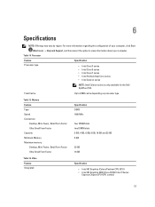
...; Intel Celeron series NOTE: Intel Celeron series is only available for the Dell OptiPlex 7010. Total Cache Up to view information about your computer. Memory Feature Type Speed Connectors: Desktop, Mini-Tower, Small Form Factor Ultra Small Form Factor Capacity Minimum Memory Maximum memory: Desktop, Mini-Tower, Small Form Factor Ultra Small Form Factor Specification DDR3...
...; Intel Celeron series NOTE: Intel Celeron series is only available for the Dell OptiPlex 7010. Total Cache Up to view information about your computer. Memory Feature Type Speed Connectors: Desktop, Mini-Tower, Small Form Factor Ultra Small Form Factor Capacity Minimum Memory Maximum memory: Desktop, Mini-Tower, Small Form Factor Ultra Small Form Factor Specification DDR3...
Owner's Manual (Desktop)
Page 61
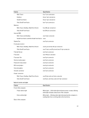
... computer. Feature Specification Mini-Tower four 7-pin connectors Desktop three 7-pin connectors Small Form Factor three 7-pin connectors Ultra Small Form Factor two 7-pin connectors Memory: Mini-Tower, Desktop, Small Form Factor four 240-pin connectors Ultra Small Form Factor two 240-pin connectors Internal USB: Mini-Tower and Desktop one...
... computer. Feature Specification Mini-Tower four 7-pin connectors Desktop three 7-pin connectors Small Form Factor three 7-pin connectors Ultra Small Form Factor two 7-pin connectors Memory: Mini-Tower, Desktop, Small Form Factor four 240-pin connectors Ultra Small Form Factor two 240-pin connectors Internal USB: Mini-Tower and Desktop one...

Owner's Manual (Mini-Tower)
Page 3
... Intrusion Switch...9 Removing the Front Bezel...9 Installing the Front Bezel...10 Removing the Expansion Cards...10 Installing the Expansion Card...12 Memory Module Guidelines...12 Removing the Memory...12 Installing the Memory...13 Removing the Coin-Cell Battery...13 Installing the Coin-Cell Battery...13 Removing the Hard Drive...14 Installing the Hard...
... Intrusion Switch...9 Removing the Front Bezel...9 Installing the Front Bezel...10 Removing the Expansion Cards...10 Installing the Expansion Card...12 Memory Module Guidelines...12 Removing the Memory...12 Installing the Memory...13 Removing the Coin-Cell Battery...13 Installing the Coin-Cell Battery...13 Removing the Hard Drive...14 Installing the Hard...
Owner's Manual (Mini-Tower)
Page 12
...GB), but all populated channels must have identical configurations. • Memory modules must be labelled differently depending on each side of the memory modules, and lift the memory modules out of the slowest installed memory module(s). Insert the expansion card into it is securely in the sockets... with the white release levers. • If memory modules with the first socket. Install the cover. 4. NOTE: The memory sockets in your system memory: • Memory modules of your computer, observe the following general guidelines when configuring your ...
...GB), but all populated channels must have identical configurations. • Memory modules must be labelled differently depending on each side of the memory modules, and lift the memory modules out of the slowest installed memory module(s). Insert the expansion card into it is securely in the sockets... with the white release levers. • If memory modules with the first socket. Install the cover. 4. NOTE: The memory sockets in your system memory: • Memory modules of your computer, observe the following general guidelines when configuring your ...
Owner's Manual (Mini-Tower)
Page 13
... the Coin-Cell Battery 1. Install the expansion card. 4. Removing the Coin-Cell Battery 1. Locate the coin-cell battery on the memory-card with the tab in the system-board connector. 2. Installing the Memory 1. Install the cover. 4. Remove the expansion card(s). 5. Press the coin cell battery downward until the release tabs spring back... out of the computer. Place the coin cell battery into place and secures it. 3. Align the notch on the system board. 4. Press down on the memory module until the release latch springs back into its slot on the system board. 2.
... the Coin-Cell Battery 1. Install the expansion card. 4. Removing the Coin-Cell Battery 1. Locate the coin-cell battery on the memory-card with the tab in the system-board connector. 2. Installing the Memory 1. Install the cover. 4. Remove the expansion card(s). 5. Press the coin cell battery downward until the release tabs spring back... out of the computer. Place the coin cell battery into place and secures it. 3. Align the notch on the system board. 4. Press down on the memory module until the release latch springs back into its slot on the system board. 2.

Owner's Manual (Mini-Tower)
Page 31
Remove the screws that secure the system board to the system board. 4. Slide the system board towards the front of the computer. 31 b) memory c) expansion card(s) d) heat sink e) processor 3. Disconnect all the cables connected to the computer. 5.
Remove the screws that secure the system board to the system board. 4. Slide the system board towards the front of the computer. 31 b) memory c) expansion card(s) d) heat sink e) processor 3. Disconnect all the cables connected to the computer. 5.
Owner's Manual (Mini-Tower)
Page 33
.... Password reset jumper 21. PCIe x1 slot 4. ATX 24-pin power connector 14. PCI slot 3. Front panel USB connector 16. Intrusion switch connector 7. DDR DIMM memory slots (4) 12. SATA connectors 15. Thermal sensor connector 19. Components Of The System Board 1. PCI Express x16 slot 6. Front power-button connector 13. CPU Socket...
.... Password reset jumper 21. PCIe x1 slot 4. ATX 24-pin power connector 14. PCI slot 3. Front panel USB connector 16. Intrusion switch connector 7. DDR DIMM memory slots (4) 12. SATA connectors 15. Thermal sensor connector 19. Components Of The System Board 1. PCI Express x16 slot 6. Front power-button connector 13. CPU Socket...


