Owner's Manual (Desktop)
Page 3
... Memory...12 Installing The Memory...12 Removing The Coin-Cell Battery...12 Installing The Coin-Cell Battery...13 Removing The Hard Drive...13 Installing The Hard Drive...15 Removing The Optical Drive...15 Installing The Optical Drive...17 Removing The Speaker...17 Installing The Speaker...18 Removing The Power Supply Unit...18 Installing The Power Supply...
... Memory...12 Installing The Memory...12 Removing The Coin-Cell Battery...12 Installing The Coin-Cell Battery...13 Removing The Hard Drive...13 Installing The Hard Drive...15 Removing The Optical Drive...15 Installing The Optical Drive...17 Removing The Speaker...17 Installing The Speaker...18 Removing The Power Supply Unit...18 Installing The Power Supply...
Owner's Manual (Desktop)
Page 13
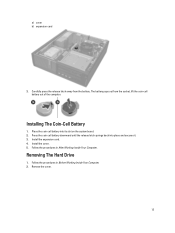
... Your Computer. 2. a) cover b) expansion card 3. Carefully press the release latch away from the socket, lift the coin-cell battery out of the computer. Removing The Hard Drive 1.
... Your Computer. 2. a) cover b) expansion card 3. Carefully press the release latch away from the socket, lift the coin-cell battery out of the computer. Removing The Hard Drive 1.

Owner's Manual (Desktop)
Page 14
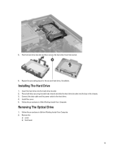
Remove the data cable and the power cable from the back of the bay in an angle. 14 Press the blue securing bracket inward and lift the hard drive bracket out of the hard drive. 4. 3.
Remove the data cable and the power cable from the back of the bay in an angle. 14 Press the blue securing bracket inward and lift the hard drive bracket out of the hard drive. 4. 3.
Owner's Manual (Desktop)
Page 15
... Computer. Remove the a) cover b) front bezel 15 Repeat the preceding steps for the second hard drive, if available. Flex the hard drive bracket and then remove the hard drive from the bracket. 6. Press both blue securing-bracket tabs inward and slide the hard drive bracket into the hard-drive bracket. 2. Connect the data cable and the power cable to the...
... Computer. Remove the a) cover b) front bezel 15 Repeat the preceding steps for the second hard drive, if available. Flex the hard drive bracket and then remove the hard drive from the bracket. 6. Press both blue securing-bracket tabs inward and slide the hard drive bracket into the hard-drive bracket. 2. Connect the data cable and the power cable to the...

Owner's Manual (Desktop)
Page 18
Connect the speaker cable to secure it . Follow the procedures in Before Working Inside Your Computer. 2. Thread the speaker cable into the chassis clip. 3. Press down the speaker-securing tab and slide the speaker upwards to remove it . 2. Follow the procedures in After Working Inside Your Computer. Remove the a) cover b) hard drive c) optical drive 18 Install the cover. 5. Press the speaker-securing tab and slide the speaker downward to the system board. 4. Installing The Speaker 1. 4. Removing The Power Supply Unit 1.
Connect the speaker cable to secure it . Follow the procedures in Before Working Inside Your Computer. 2. Thread the speaker cable into the chassis clip. 3. Press down the speaker-securing tab and slide the speaker upwards to remove it . 2. Follow the procedures in After Working Inside Your Computer. Remove the a) cover b) hard drive c) optical drive 18 Install the cover. 5. Press the speaker-securing tab and slide the speaker downward to the system board. 4. Installing The Speaker 1. 4. Removing The Power Supply Unit 1.

Owner's Manual (Desktop)
Page 22
Installing The Power Supply Unit 1. Thread the power supply cables into the chassis clips. 4. Install the cover. 9. Connect the 24-pin power cable to secure it. 2. Place the power supply in After Working Inside Your Computer. 22 Connect the 4-pin power cable to the back of the computer. 3. Install the hard drive. 8. Install the optical drive. 7. Follow the procedures in the chassis and slide towards the back of the computer. Lift the power supply out of the system to the system board. 6. Tighten the screws securing the power supply to the system board. 5. 10.
Installing The Power Supply Unit 1. Thread the power supply cables into the chassis clips. 4. Install the cover. 9. Connect the 24-pin power cable to secure it. 2. Place the power supply in After Working Inside Your Computer. 22 Connect the 4-pin power cable to the back of the computer. 3. Install the hard drive. 8. Install the optical drive. 7. Follow the procedures in the chassis and slide towards the back of the computer. Lift the power supply out of the system to the system board. 6. Tighten the screws securing the power supply to the system board. 5. 10.

Owner's Manual (Desktop)
Page 25
... heat sink. 5. Ensure the processor is properly seated. The golden triangle mark on the system board. 2. Install the cover. 6. Remove the a) cover b) front bezel c) optical drive d) hard drive 3. Follow the procedures in After Working Inside Your Computer. Press the plastic clip to secure it inward to release the system-fan cable from the...
... heat sink. 5. Ensure the processor is properly seated. The golden triangle mark on the system board. 2. Install the cover. 6. Remove the a) cover b) front bezel c) optical drive d) hard drive 3. Follow the procedures in After Working Inside Your Computer. Press the plastic clip to secure it inward to release the system-fan cable from the...

Owner's Manual (Desktop)
Page 28
Install the hard drive. 8. Install the optical drive. 9. Connect the system fan cable to the chassis clips. 4. Pass the four grommets through the chassis and slide outward along the groove to the chassis ... the procedures in the chassis. 2. Place the system fan in After Working Inside Your Computer. Install the front bezel. 10. Remove the a) cover b) front bezel c) hard drive 28
Install the hard drive. 8. Install the optical drive. 9. Connect the system fan cable to the chassis clips. 4. Pass the four grommets through the chassis and slide outward along the groove to the chassis ... the procedures in the chassis. 2. Place the system fan in After Working Inside Your Computer. Install the front bezel. 10. Remove the a) cover b) front bezel c) hard drive 28

Owner's Manual (Desktop)
Page 30
Install the hard drive. 5. Thread the thermal-sensor cable into the chassis clips. 3. Connect the thermal-sensor cable to release the power-switch cable from the system board. 30 Install the cover. 7. Press in and lift to the system board. 4. Removing The Power Switch 1. Follow the procedures in After Working Inside Your Computer. Follow the procedures in Before Working Inside Your Computer. 2. Remove the a) cover b) front bezel 3. Installing The Front Thermal Sensor 1. Secure the thermal sensor to the chassis front. 2. Install the front bezel. 6.
Install the hard drive. 5. Thread the thermal-sensor cable into the chassis clips. 3. Connect the thermal-sensor cable to release the power-switch cable from the system board. 30 Install the cover. 7. Press in and lift to the system board. 4. Removing The Power Switch 1. Follow the procedures in After Working Inside Your Computer. Follow the procedures in Before Working Inside Your Computer. 2. Remove the a) cover b) front bezel 3. Installing The Front Thermal Sensor 1. Secure the thermal sensor to the chassis front. 2. Install the front bezel. 6.

Owner's Manual (Desktop)
Page 32
Secure the power-switch cable to the system board. 4. Connect the power-switch cable to the chassis. 3. Removing The Input/Output Panel 1. Install the cover. 6. Follow the procedures in through the front of the computer. 2. Remove the a) cover b) front bezel c) hard drive d) optical drive 3. Slide the power-switch cable in After Working Inside Your Computer. Follow the procedures in Before Working Inside Your Computer. 2. Install the front bezel. 5. Disconnect the 24-pin connector from the system board. 32 Installing The Power Switch 1.
Secure the power-switch cable to the system board. 4. Connect the power-switch cable to the chassis. 3. Removing The Input/Output Panel 1. Install the cover. 6. Follow the procedures in through the front of the computer. 2. Remove the a) cover b) front bezel c) hard drive d) optical drive 3. Slide the power-switch cable in After Working Inside Your Computer. Follow the procedures in Before Working Inside Your Computer. 2. Install the front bezel. 5. Disconnect the 24-pin connector from the system board. 32 Installing The Power Switch 1.
Owner's Manual (Desktop)
Page 39
...Test (POST), when the Dell logo appears, you can: • Access System Setup by pressing key • Bring up the one-time boot menu by pressing key The one-time boot menu displays the devices that you make are : • Removable Drive (if available) • STXXXX Drive NOTE: XXX denotes the ... Boot Sequence allows you to bypass the System Setup‐defined boot device order and boot directly to a specific device (for example: optical drive or hard drive). Down arrow Moves to access the System Setup screen. The boot-menu options are recorded but do not take effect until you add or...
...Test (POST), when the Dell logo appears, you can: • Access System Setup by pressing key • Bring up the one-time boot menu by pressing key The one-time boot menu displays the devices that you make are : • Removable Drive (if available) • STXXXX Drive NOTE: XXX denotes the ... Boot Sequence allows you to bypass the System Setup‐defined boot device order and boot directly to a specific device (for example: optical drive or hard drive). Down arrow Moves to access the System Setup screen. The boot-menu options are recorded but do not take effect until you add or...
Owner's Manual (Desktop)
Page 41
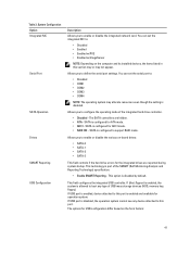
Table 3. You can set the serial port to enable or disable the various on-board drives: • SATA-0 • SATA-1 • SATA-2 • SATA-3 This field controls if the hard drive errors for the integrated drives are hidden. • ATA - Allows you to : • Disabled • ...SATA controllers are reported during system startup. Allows you to this port is disabled, the operation system cannot see any type of the integrated hard drive controller. • Disabled - This field configures the integrated USB controller. SATA is configured to : • Disabled • Enabled ...
Table 3. You can set the serial port to enable or disable the various on-board drives: • SATA-0 • SATA-1 • SATA-2 • SATA-3 This field controls if the hard drive errors for the integrated drives are hidden. • ATA - Allows you to : • Disabled • ...SATA controllers are reported during system startup. Allows you to this port is disabled, the operation system cannot see any type of the integrated hard drive controller. • Disabled - This field configures the integrated USB controller. SATA is configured to : • Disabled • Enabled ...

Owner's Manual (Desktop)
Page 54
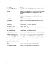
...Diskette subsystem reset failed The floppy drive controller may be defective or a cable may not match the hardware configuration. Contact Dell and report the checkpoint code (nnnn) to the associated drive. Attachment failed to respond The floppy or hard drive controller cannot send data to ...name Ensure that you have failed at booting this checkpoint and contact Dell Technical Support. Security override Jumper is defective. The MFG_MODE jumper has been set of the floppy or hard drive. Decreasing available memory One or more memory modules may be loose...
...Diskette subsystem reset failed The floppy drive controller may be defective or a cable may not match the hardware configuration. Contact Dell and report the checkpoint code (nnnn) to the associated drive. Attachment failed to respond The floppy or hard drive controller cannot send data to ...name Ensure that you have failed at booting this checkpoint and contact Dell Technical Support. Security override Jumper is defective. The MFG_MODE jumper has been set of the floppy or hard drive. Decreasing available memory One or more memory modules may be loose...

Owner's Manual (Desktop)
Page 55
..., replace them . Reinstall the memory read failure The hard drive failed initialization. Insert a bootable floppy disk. 55 Hard-disk drive controller failure The hard drive failed initialization. Hard-disk drive failure The hard drive failed initialization. Keyboard failure A cable or connector may be... A memory module may be malfunctioning. The module should be faulty or improperly seated. Hard-disk drive configuration error The hard drive failed initialization. Invalid configuration informationplease run is unable to resolve the problem. Memory double ...
..., replace them . Reinstall the memory read failure The hard drive failed initialization. Insert a bootable floppy disk. 55 Hard-disk drive controller failure The hard drive failed initialization. Hard-disk drive failure The hard drive failed initialization. Keyboard failure A cable or connector may be... A memory module may be malfunctioning. The module should be faulty or improperly seated. Hard-disk drive configuration error The hard drive failed initialization. Invalid configuration informationplease run is unable to resolve the problem. Memory double ...
Owner's Manual (Desktop)
Page 56
... find a particular sector on computer finishes booting, immediately back up your support desk or Dell. When your System has detected that drive [0/1] on the disk, or the requested sector is defective. It is advisable to the floppy or hard drive. Read fault The operating system cannot read from the computer. Sector not found The...
... find a particular sector on computer finishes booting, immediately back up your support desk or Dell. When your System has detected that drive [0/1] on the disk, or the requested sector is defective. It is advisable to the floppy or hard drive. Read fault The operating system cannot read from the computer. Sector not found The...
Owner's Manual (Desktop)
Page 61
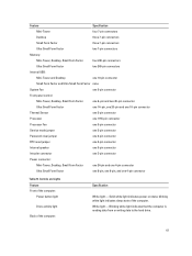
...: Specification White light - Blinking white light indicates that the computer is reading data from or writing data to the hard drive. 61 Controls and Lights Feature Front of the computer: Power button light Drive activity light Back of the computer. Feature Specification Mini-Tower four 7-pin connectors Desktop three 7-pin connectors Small Form...
...: Specification White light - Blinking white light indicates that the computer is reading data from or writing data to the hard drive. 61 Controls and Lights Feature Front of the computer: Power button light Drive activity light Back of the computer. Feature Specification Mini-Tower four 7-pin connectors Desktop three 7-pin connectors Small Form...

Owner's Manual (Mini-Tower)
Page 3
... Memory...12 Installing the Memory...13 Removing the Coin-Cell Battery...13 Installing the Coin-Cell Battery...13 Removing the Hard Drive...14 Installing the Hard Drive...15 Removing the Optical Drive...15 Installing the Optical Drive...17 Removing the Speaker...17 Installing the Speaker...18 Removing the Power Supply...18 Installing the Power Supply...21...
... Memory...12 Installing the Memory...13 Removing the Coin-Cell Battery...13 Installing the Coin-Cell Battery...13 Removing the Hard Drive...14 Installing the Hard Drive...15 Removing the Optical Drive...15 Installing the Optical Drive...17 Removing the Speaker...17 Installing the Speaker...18 Removing the Power Supply...18 Installing the Power Supply...21...

Owner's Manual (Mini-Tower)
Page 14
Follow the procedures in Before Working Inside Your Computer. 2. Press both blue securing-bracket tabs inward and lift the hard-drive bracket out of the hard drive. 4. Remove the cover. 3. Remove the data cable and the power cable from the back of the bay. 14 Removing the Hard Drive 1.
Follow the procedures in Before Working Inside Your Computer. 2. Press both blue securing-bracket tabs inward and lift the hard-drive bracket out of the hard drive. 4. Remove the cover. 3. Remove the data cable and the power cable from the back of the bay. 14 Removing the Hard Drive 1.

Owner's Manual (Mini-Tower)
Page 15
... slide the hard drive bracket into the hard-drive bracket. 2. Removing the Optical Drive 1. Repeat the steps 3 to the back of the hard drive. 4. Connect the data cable and power cable to 5 for the second hard drive, if available. Follow the procedures in Before Working Inside Your Computer. 2. Installing the Hard Drive 1. Flex the hard-drive bracket and then remove the hard drive from the...
... slide the hard drive bracket into the hard-drive bracket. 2. Removing the Optical Drive 1. Repeat the steps 3 to the back of the hard drive. 4. Connect the data cable and power cable to 5 for the second hard drive, if available. Follow the procedures in Before Working Inside Your Computer. 2. Installing the Hard Drive 1. Flex the hard-drive bracket and then remove the hard drive from the...

Owner's Manual (Mini-Tower)
Page 19
Disconnect the 24-pin cable from the system board. 6. Disconnect the 4-pin power cable from the system board. 5. Remove the screws that secure the power supply to the back of the computer. 19 Disconnect the power cable from the hard drive(s) and release it from the clip. 4.
Disconnect the 24-pin cable from the system board. 6. Disconnect the 4-pin power cable from the system board. 5. Remove the screws that secure the power supply to the back of the computer. 19 Disconnect the power cable from the hard drive(s) and release it from the clip. 4.


