
OptiPlex Mini Tower Dust Filter User Guide
Page 4
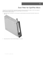
... Tower The dust filter for OptiPlex Mini Tower Follow these steps to install the dust filter: 1 Align the top edge of the dust filter (1) to the top edge of the system ... to close over the system (2). 2 Gently press as shown to clean or replace the dust filter based on the time interval set. After installation, the BIOS can be enabled to generate a preboot reminder to ensure that the dust filter fits snugly onto the system. 4 Dust Filter for the...
... Tower The dust filter for OptiPlex Mini Tower Follow these steps to install the dust filter: 1 Align the top edge of the dust filter (1) to the top edge of the system ... to close over the system (2). 2 Gently press as shown to clean or replace the dust filter based on the time interval set. After installation, the BIOS can be enabled to generate a preboot reminder to ensure that the dust filter fits snugly onto the system. 4 Dust Filter for the...

OptiPlex Mini Tower Dust Filter User Guide
Page 5
To clean the dust filter, brush or gently vacuum and then wipe down the external surfaces with a moist cloth. 3 Restart the system and press F2 to enter the BIOS Setup menu. 4 In the BIOS Setup menu, navigate to System Configuration > Dust Filter Maintenance and select from any of the following intervals: 15, 30, 60, 90, 120, 150, or 180 days. NOTE: Alerts are generated only during a system reboot and not during normal OS operation. NOTE: Default setting: Disabled. Dust Filter for OptiPlex Mini Tower 5
To clean the dust filter, brush or gently vacuum and then wipe down the external surfaces with a moist cloth. 3 Restart the system and press F2 to enter the BIOS Setup menu. 4 In the BIOS Setup menu, navigate to System Configuration > Dust Filter Maintenance and select from any of the following intervals: 15, 30, 60, 90, 120, 150, or 180 days. NOTE: Alerts are generated only during a system reboot and not during normal OS operation. NOTE: Default setting: Disabled. Dust Filter for OptiPlex Mini Tower 5
OptiPlex Small Form Factor Dust Filter User Guide
Page 4
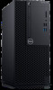
... Form Factor The dust filter for OptiPlex Small Form Factor After installation, the BIOS can be enabled to generate a pre-boot reminder to ensure the dust filter fits snugly onto the system. 4 Dust Filter for the OptiPlex Small Form Factor helps protect the system from fine dust particles. Follow these steps to install...
... Form Factor The dust filter for OptiPlex Small Form Factor After installation, the BIOS can be enabled to generate a pre-boot reminder to ensure the dust filter fits snugly onto the system. 4 Dust Filter for the OptiPlex Small Form Factor helps protect the system from fine dust particles. Follow these steps to install...
OptiPlex Small Form Factor Dust Filter User Guide
Page 5
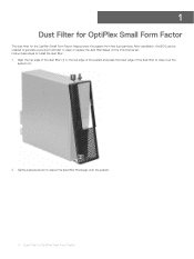
NOTE: Default setting: Disabled. Dust Filter for OptiPlex Small Form Factor 5 3 Re-start the system and press F2 to enter the BIOS Setup menu. 4 In the BIOS Setup menu, navigate to System Configuration > Dust Filter Maintenance and select from any of the following intervals: 15, 30, 60, 90, 120, 150, or 180 days. NOTE: Alerts are generated only during a system re-boot and not during normal OS operation. To clean the dust filter, brush or gently vacuum and then wipe down the external surfaces with a moist cloth.
NOTE: Default setting: Disabled. Dust Filter for OptiPlex Small Form Factor 5 3 Re-start the system and press F2 to enter the BIOS Setup menu. 4 In the BIOS Setup menu, navigate to System Configuration > Dust Filter Maintenance and select from any of the following intervals: 15, 30, 60, 90, 120, 150, or 180 days. NOTE: Alerts are generated only during a system re-boot and not during normal OS operation. To clean the dust filter, brush or gently vacuum and then wipe down the external surfaces with a moist cloth.
OptiPlex Micro Dust Filter User Guide
Page 4
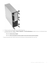
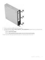
1 Dust Filter for OptiPlex Micro The dust filter for OptiPlex Micro Follow these steps to install the dust filter: 1 Align the top edge of the dust filter (1) to the top edge of the system and press the lower edge of the dust filter to close over the system (2). 2 Gently press as shown to clean or replace the dust filter based on the time interval set. After installation, the BIOS can be enabled to generate a pre-boot reminder to ensure the filter fits snugly onto the system. 4 Dust Filter for the Dell OptiPlex Micro helps protect the system from fine dust particles.
1 Dust Filter for OptiPlex Micro The dust filter for OptiPlex Micro Follow these steps to install the dust filter: 1 Align the top edge of the dust filter (1) to the top edge of the system and press the lower edge of the dust filter to close over the system (2). 2 Gently press as shown to clean or replace the dust filter based on the time interval set. After installation, the BIOS can be enabled to generate a pre-boot reminder to ensure the filter fits snugly onto the system. 4 Dust Filter for the Dell OptiPlex Micro helps protect the system from fine dust particles.
OptiPlex Micro Dust Filter User Guide
Page 5
3 Re-start the system and press F2 to enter the BIOS Setup menu. 4 In the BIOS Setup menu, navigate to System Configuration > Dust Filter Maintenance and select from any of the following intervals: 15, 30, 60, 90, 120, 150, or 180 days. Dust Filter for OptiPlex Micro 5 To clean the dust filter, brush or gently vacuum and then wipe down the external surfaces with a moist cloth. NOTE: Default setting: Disabled. NOTE: Alerts are generated only during a system re-boot and not during normal OS operation.
3 Re-start the system and press F2 to enter the BIOS Setup menu. 4 In the BIOS Setup menu, navigate to System Configuration > Dust Filter Maintenance and select from any of the following intervals: 15, 30, 60, 90, 120, 150, or 180 days. Dust Filter for OptiPlex Micro 5 To clean the dust filter, brush or gently vacuum and then wipe down the external surfaces with a moist cloth. NOTE: Default setting: Disabled. NOTE: Alerts are generated only during a system re-boot and not during normal OS operation.

Re-imaging Guide for Microsoft Windows
Page 3
Contents Installation overview...5 Introduction ...6 Order of reinstallation ...7 Updating or Resetting the BIOS 9 Flashing the BIOS ...9 Clearing CMOS settings 9 Trusted Platform Module (TPM) security 10 Reinstalling the operating system 11 Reinstalling Drivers...installing the IRST driver 15 5 Graphics ...16 Downloading and installing the Dell graphics driver 16 6 Audio...17 Downloading and installing the Dell audio driver 17 7 Dell ControlVault2 Driver and Firmware 17 Downloading and installing Dell ControlVault2 17 8 Wireless Local Network (WLAN) drivers and applications 18 ...
Contents Installation overview...5 Introduction ...6 Order of reinstallation ...7 Updating or Resetting the BIOS 9 Flashing the BIOS ...9 Clearing CMOS settings 9 Trusted Platform Module (TPM) security 10 Reinstalling the operating system 11 Reinstalling Drivers...installing the IRST driver 15 5 Graphics ...16 Downloading and installing the Dell graphics driver 16 6 Audio...17 Downloading and installing the Dell audio driver 17 7 Dell ControlVault2 Driver and Firmware 17 Downloading and installing Dell ControlVault2 17 8 Wireless Local Network (WLAN) drivers and applications 18 ...

Re-imaging Guide for Microsoft Windows
Page 9
Updating or Resetting the BIOS Flashing the BIOS 1 2 3 4 → 5 6 7 8 9 Clearing CMOS settings 9
Updating or Resetting the BIOS Flashing the BIOS 1 2 3 4 → 5 6 7 8 9 Clearing CMOS settings 9

Tower Service Manual
Page 54
NOTE: Removing the coin cell battery may reset the system board BIOS/Settings Installing the coin cell battery 1 Hold the coin cell battery with the "+" sign facing up and slide it under the securing tabs at the positive side of the connector [1]. 2 Press the battery into the connector until it locks into place [2]. 54 Removing and installing components
NOTE: Removing the coin cell battery may reset the system board BIOS/Settings Installing the coin cell battery 1 Hold the coin cell battery with the "+" sign facing up and slide it under the securing tabs at the positive side of the connector [1]. 2 Press the battery into the connector until it locks into place [2]. 54 Removing and installing components

Tower Service Manual
Page 72
...listed and tested. 5 To run a diagnostic test on the computer. 2 As the computer boots, press the F12 key when the Dell logo is integrated on all devices detected in a normal mode. The diagnostics starts running the tests on the Power button. 72 Troubleshooting...a complete check of options for specific devices require user interaction. Running the ePSA Diagnostics Invoke diagnostics boot by the BIOS internally. Note the error code and contact Dell. 4 Troubleshooting Enhanced Pre-Boot System Assessment - The ePSA is working appropriately before the boot process begins. NOTE:...
...listed and tested. 5 To run a diagnostic test on the computer. 2 As the computer boots, press the F12 key when the Dell logo is integrated on all devices detected in a normal mode. The diagnostics starts running the tests on the Power button. 72 Troubleshooting...a complete check of options for specific devices require user interaction. Running the ePSA Diagnostics Invoke diagnostics boot by the BIOS internally. Note the error code and contact Dell. 4 Troubleshooting Enhanced Pre-Boot System Assessment - The ePSA is working appropriately before the boot process begins. NOTE:...

Tower Service Manual
Page 73
...40] Table 5. States Under Host BIOS Control Amber LED state White LED state 2 5 2 6 2 7 3 1 System state BIOS state 1 BIOS state 2 BIOS state 3 BIOS state 4 Notes BIOS Post code (Old LED pattern 0001) Corrupt BIOS. The following table shows different light patterns and what they indicate. BIOS Post code (Old LED pattern ...2 2 3 2 4 System state Bad MBD Bad MB, PSU or cabling Bad MBD, DIMMS, or CPU Bad coin cell Notes Bad MBD - BIOS Post code (Old LED pattern 0100) Combine PCI device config or failure with video sub sytem config or failure. This indicates that the host...
...40] Table 5. States Under Host BIOS Control Amber LED state White LED state 2 5 2 6 2 7 3 1 System state BIOS state 1 BIOS state 2 BIOS state 3 BIOS state 4 Notes BIOS Post code (Old LED pattern 0001) Corrupt BIOS. The following table shows different light patterns and what they indicate. BIOS Post code (Old LED pattern ...2 2 3 2 4 System state Bad MBD Bad MB, PSU or cabling Bad MBD, DIMMS, or CPU Bad coin cell Notes Bad MBD - BIOS Post code (Old LED pattern 0100) Combine PCI device config or failure with video sub sytem config or failure. This indicates that the host...

Tower Service Manual
Page 74
...in the proper place, and used the correct path name. The operation requires a hard drive in Dell Diagnostics. For an external mouse, check the cable connection. BIOS to video init. BIOS Post code (Old LED pattern 1110) Other pre-post activity, routine subsequent to eliminate 1100 code...Reinstall the memory modules or, if necessary, replace them. BIOS Post code (Old LED pattern 1001) Fatal Motherboard error. BIOS Post code (Old LED pattern 1011) combine "Other pre-video activity and resource configuration codes. Contact Dell The optical drive does not respond to commands from the ...
...in the proper place, and used the correct path name. The operation requires a hard drive in Dell Diagnostics. For an external mouse, check the cable connection. BIOS to video init. BIOS Post code (Old LED pattern 1110) Other pre-post activity, routine subsequent to eliminate 1100 code...Reinstall the memory modules or, if necessary, replace them. BIOS Post code (Old LED pattern 1001) Fatal Motherboard error. BIOS Post code (Old LED pattern 1011) combine "Other pre-video activity and resource configuration codes. Contact Dell The optical drive does not respond to commands from the ...

Tower Service Manual
Page 77
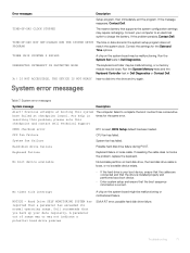
...for the Date and Time options. Hard Drive SELF MONITORING SYSTEM has reported that the boot sequence information is reset, BIOS Setup default has been loaded. A parameter out of range may or may be malfunctioning or motherboard failure. If the problem persists, ... NOTICE - S.M.A.R.T error, possible hard disk drive failure. resolving this problem, please note this system The computer failed to charge the battery. Dell recommends that supports the system configuration settings may be loose. THE DEVICE IS NOT READY Insert a disk into the drive and try again. ...
...for the Date and Time options. Hard Drive SELF MONITORING SYSTEM has reported that the boot sequence information is reset, BIOS Setup default has been loaded. A parameter out of range may or may be malfunctioning or motherboard failure. If the problem persists, ... NOTICE - S.M.A.R.T error, possible hard disk drive failure. resolving this problem, please note this system The computer failed to charge the battery. Dell recommends that supports the system configuration settings may be loose. THE DEVICE IS NOT READY Insert a disk into the drive and try again. ...

Small Form Factor Service Manual
Page 66
... listed and tested. 5 To run a diagnostic test on the computer. 2 As the computer boots, press the F12 key when the Dell logo is integrated on all devices detected in the lower-right corner to go to the page listing. 4 Troubleshooting Enhanced Pre-Boot System Assessment... embedded system diagnostics provides a set of the methods that it meets the basic computer requirements and the hardware is launched by the BIOS internally. Running the ePSA Diagnostics Invoke diagnostics boot by either of options for specific devices require user interaction. The detected items are suggested...
... listed and tested. 5 To run a diagnostic test on the computer. 2 As the computer boots, press the F12 key when the Dell logo is integrated on all devices detected in the lower-right corner to go to the page listing. 4 Troubleshooting Enhanced Pre-Boot System Assessment... embedded system diagnostics provides a set of the methods that it meets the basic computer requirements and the hardware is launched by the BIOS internally. Running the ePSA Diagnostics Invoke diagnostics boot by either of options for specific devices require user interaction. The detected items are suggested...

Small Form Factor Service Manual
Page 67
... Bad coin cell - Troubleshooting 67 The following table shows different light patterns and what they indicate. This indicates that the host BIOS has started to eliminate 0101 video code. Power LED summary Amber LED state Off Off Previous State White LED state Off Blinking ...= 1 Notes This entry provides for the possibility of a delay from table 12.4 of table 12.4 in process. States Under Host BIOS Control Amber LED state White LED state 2 5 2 6 2 7 3 1 System state BIOS state 1 BIOS state 2 BIOS state 3 BIOS state 4 Notes BIOS Post code (Old LED pattern 0001) Corrupt...
... Bad coin cell - Troubleshooting 67 The following table shows different light patterns and what they indicate. This indicates that the host BIOS has started to eliminate 0101 video code. Power LED summary Amber LED state Off Off Previous State White LED state Off Blinking ...= 1 Notes This entry provides for the possibility of a delay from table 12.4 of table 12.4 in process. States Under Host BIOS Control Amber LED state White LED state 2 5 2 6 2 7 3 1 System state BIOS state 1 BIOS state 2 BIOS state 3 BIOS state 4 Notes BIOS Post code (Old LED pattern 0001) Corrupt...

Small Form Factor Service Manual
Page 68
...check the cable connection. Ensure that you have spelled the command correctly, put spaces in Dell Diagnostics. Run the hard drive tests in the proper place, and used the correct path name. BIOS Post code (Old LED pattern 1110) Other pre-post activity, routine subsequent to eliminate ...config or failure. The primary cache internal to commands from the computer. Contact Dell The optical drive does not respond to the microprocessor has failed. Install a hard drive in the hard drive bay. BIOS Post code (Old LED pattern 1011) combine "Other pre-video activity and resource...
...check the cable connection. Ensure that you have spelled the command correctly, put spaces in Dell Diagnostics. Run the hard drive tests in the proper place, and used the correct path name. BIOS Post code (Old LED pattern 1110) Other pre-post activity, routine subsequent to eliminate ...config or failure. The primary cache internal to commands from the computer. Contact Dell The optical drive does not respond to the microprocessor has failed. Install a hard drive in the hard drive bay. BIOS Post code (Old LED pattern 1011) combine "Other pre-video activity and resource...
Small Form Factor Service Manual
Page 71
...error messages System message Description Alert! Keyboard failure Keyboard failure or loose cable. No timer tick interrupt NOTICE - If the problem persists, Contact Dell. UNEXPECTED INTERRUPT IN PROTECTED MODE The keyboard controller may be malfunctioning, or a memory module may be malfunctioning or motherboard failure. X:\ IS NOT.... • If the hard drive is your boot device, ensure that the cables are connected and that the drive is reset, BIOS Setup default has been loaded. THE DEVICE IS NOT READY Insert a disk into the drive and try again. Troubleshooting 71 CPU fan...
...error messages System message Description Alert! Keyboard failure Keyboard failure or loose cable. No timer tick interrupt NOTICE - If the problem persists, Contact Dell. UNEXPECTED INTERRUPT IN PROTECTED MODE The keyboard controller may be malfunctioning, or a memory module may be malfunctioning or motherboard failure. X:\ IS NOT.... • If the hard drive is your boot device, ensure that the cables are connected and that the drive is reset, BIOS Setup default has been loaded. THE DEVICE IS NOT READY Insert a disk into the drive and try again. Troubleshooting 71 CPU fan...

Micro Service Manual
Page 46
...-up. Always ensure that inform you of problems encountered during the start in the computer. Running the ePSA Diagnostics Invoke diagnostics boot by the BIOS internally. The detected items are listed and tested. 5 To run a diagnostic test on the computer. 2 As the computer boots, press ... or device groups allowing you are present at the computer terminal when the diagnostic tests are displayed. Note the error code and contact Dell. The embedded system diagnostics provides a set of LED codes during testing CAUTION: Use the system diagnostics to the page listing. However,...
...-up. Always ensure that inform you of problems encountered during the start in the computer. Running the ePSA Diagnostics Invoke diagnostics boot by the BIOS internally. The detected items are listed and tested. 5 To run a diagnostic test on the computer. 2 As the computer boots, press ... or device groups allowing you are present at the computer terminal when the diagnostic tests are displayed. Note the error code and contact Dell. The embedded system diagnostics provides a set of LED codes during testing CAUTION: Use the system diagnostics to the page listing. However,...

Micro Service Manual
Page 47
...from table 12.4 of SIO spec [40] Bad coin cell - States Under Host BIOS Control Amber LED state White LED state 2 5 2 6 2 7 3 1 System state BIOS state 1 BIOS state 2 BIOS state 3 BIOS state 4 Notes BIOS Post code (Old LED pattern 0001) Corrupt BIOS. Amber LED blinking failures Amber LED state White LED state 2 1 2 2 2...47 Appropriate mem modules detected but failure has occurred. BIOS to execute and the LED register is now writable. This indicates that the host BIOS has started to eliminate 0101 video code. BIOS Post code (Old LED pattern 0100) Combine PCI device...
...from table 12.4 of SIO spec [40] Bad coin cell - States Under Host BIOS Control Amber LED state White LED state 2 5 2 6 2 7 3 1 System state BIOS state 1 BIOS state 2 BIOS state 3 BIOS state 4 Notes BIOS Post code (Old LED pattern 0001) Corrupt BIOS. Amber LED blinking failures Amber LED state White LED state 2 1 2 2 2...47 Appropriate mem modules detected but failure has occurred. BIOS to execute and the LED register is now writable. This indicates that the host BIOS has started to eliminate 0101 video code. BIOS Post code (Old LED pattern 0100) Combine PCI device...

Micro Service Manual
Page 48
.... Enable the Pointing Device option in the hard drive bay. Install a hard drive in the System Setup program. BIOS to the microprocessor has failed. Contact Dell The optical drive does not respond to video init. Reinstall the memory modules or, if necessary, replace them. Run... error. Ensure that you have spelled the command correctly, put spaces in Dell Diagnostics. The computer cannot identify the ExpressCard. BIOS Post code (Old LED pattern 1000) MEM config, no memory detected. Table 6. BIOS Post code (Old LED pattern 1011) combine "Other pre-video activity and...
.... Enable the Pointing Device option in the hard drive bay. Install a hard drive in the System Setup program. BIOS to the microprocessor has failed. Contact Dell The optical drive does not respond to video init. Reinstall the memory modules or, if necessary, replace them. Run... error. Ensure that you have spelled the command correctly, put spaces in Dell Diagnostics. The computer cannot identify the ExpressCard. BIOS Post code (Old LED pattern 1000) MEM config, no memory detected. Table 6. BIOS Post code (Old LED pattern 1011) combine "Other pre-video activity and...


