Setup Guide
Page 25
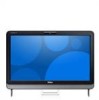
Using Your Inspiron One 5 Audio-out/Headphone connector - Turns on or off when pressed. A blinking white light indicates hard drive activity. Contact Dell (see "Contacting Dell" on page 69) for assistance. • Blinking amber - Connects to a pair of data, never turn off , or is on the back of ...- Turns the computer on when the computer reads or writes data. Connects to a powered speaker or sound system, use with the system board or the power supply. The light on self-test (POST). The computer has detected an error during Power-on the button indicates the ...
Using Your Inspiron One 5 Audio-out/Headphone connector - Turns on or off when pressed. A blinking white light indicates hard drive activity. Contact Dell (see "Contacting Dell" on page 69) for assistance. • Blinking amber - Connects to a pair of data, never turn off , or is on the back of ...- Turns the computer on when the computer reads or writes data. Connects to a powered speaker or sound system, use with the system board or the power supply. The light on self-test (POST). The computer has detected an error during Power-on the button indicates the ...

Setup Guide
Page 35
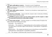
... appear on your frequently-used programs. Using Your Inspiron One • StickyNotes - Provides a preview of your favorite web pages. Provides quick access to four of up to the Internet. • Dell Web - Provides a preview of your pictures. You can also save notes on the bulletin board the next time you access STICKYNOTES. View videos...
... appear on your frequently-used programs. Using Your Inspiron One • StickyNotes - Provides a preview of your favorite web pages. Provides quick access to four of up to the Internet. • Dell Web - Provides a preview of your pictures. You can also save notes on the bulletin board the next time you access STICKYNOTES. View videos...
Setup Guide
Page 43
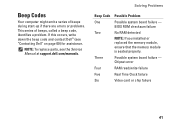
...or problems. This series of beeps, called a beep code, identifies a problem. Three Possible system board failure - If this occurs, write down the beep code and contact Dell™ (see the Service Manual at support.dell.com/manuals. Chipset error Four RAM read/write failure Five Real Time Clock failure Six Video... NOTE: If you installed or replaced the memory module, ensure that the memory module is seated properly. Solving Problems Beep Code Possible Problem One Possible system board failure - NOTE: To replace parts, see "Contacting Dell" on page 69) for assistance.
...or problems. This series of beeps, called a beep code, identifies a problem. Three Possible system board failure - If this occurs, write down the beep code and contact Dell™ (see the Service Manual at support.dell.com/manuals. Chipset error Four RAM read/write failure Five Real Time Clock failure Six Video... NOTE: If you installed or replaced the memory module, ensure that the memory module is seated properly. Solving Problems Beep Code Possible Problem One Possible system board failure - NOTE: To replace parts, see "Contacting Dell" on page 69) for assistance.
Setup Guide
Page 45
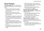
... the electrical outlet is working by testing it back on. • If the problem persists, contact Dell (see "Contacting Dell" on page 69). The computer is on. • If the problem persists, contact Dell (see "Contacting Dell" on page 69). The display may not be a problem with another device, such as a lamp... sleep/standby mode or there might be responding. • Press the power button until the computer turns off and then turn it with the system board or the power supply. • Press a key on the AC adapter is in hibernate mode, turned off or in hibernate mode. • ...
... the electrical outlet is working by testing it back on. • If the problem persists, contact Dell (see "Contacting Dell" on page 69). The computer is on. • If the problem persists, contact Dell (see "Contacting Dell" on page 69). The display may not be a problem with another device, such as a lamp... sleep/standby mode or there might be responding. • Press the power button until the computer turns off and then turn it with the system board or the power supply. • Press a key on the AC adapter is in hibernate mode, turned off or in hibernate mode. • ...
Setup Guide
Page 51
... has failed. CPU fan failure - Keyboard failure or loose cable. Replace the keyboard. No bootable partition on the system board might be malfunctioning or system board failure. No timer tick interrupt - Contact Dell (see "Contacting Dell" on page 69) for assistance. 49 System fan has failed. Hard-disk drive read failure - See the Service...
... has failed. CPU fan failure - Keyboard failure or loose cable. Replace the keyboard. No bootable partition on the system board might be malfunctioning or system board failure. No timer tick interrupt - Contact Dell (see "Contacting Dell" on page 69) for assistance. 49 System fan has failed. Hard-disk drive read failure - See the Service...

Setup Guide
Page 77
... W 1.50 A 130 W 2.30 A/2.50 A Input frequency 50-60 Hz Output power 90 W or 130 W 75 Communications Network adapter 10/100/1000 Ethernet LAN on system board Wireless Wi-Fi and Bluetooth® wireless technology Camera Pixel Video resolution 1.3 megapixel 1280 x 1024 at 8 fps 160 x 120 - 640 x 480 at 30 fps Battery...
... W 1.50 A 130 W 2.30 A/2.50 A Input frequency 50-60 Hz Output power 90 W or 130 W 75 Communications Network adapter 10/100/1000 Ethernet LAN on system board Wireless Wi-Fi and Bluetooth® wireless technology Camera Pixel Video resolution 1.3 megapixel 1280 x 1024 at 8 fps 160 x 120 - 640 x 480 at 30 fps Battery...
Service Manual
Page 1
...and trade names other countries. disclaims any proprietary interest in any manner whatsoever without notice. © 2010 Dell Inc. Dell™ Inspiron™ One 2205 Service Manual Technical Overview Before You Begin Back Cover Hard Drive Optical Drive Memory Module(s) Converter Card Touch... Screen Control Card (Optional) Front Stand Rear Stand Cover Rear Stand System-Board Shield Antenna-In Connector (Optional) Infrared ...
...and trade names other countries. disclaims any proprietary interest in any manner whatsoever without notice. © 2010 Dell Inc. Dell™ Inspiron™ One 2205 Service Manual Technical Overview Before You Begin Back Cover Hard Drive Optical Drive Memory Module(s) Converter Card Touch... Screen Control Card (Optional) Front Stand Rear Stand Cover Rear Stand System-Board Shield Antenna-In Connector (Optional) Infrared ...
Service Manual
Page 4
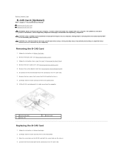
Remove the system-board shield (see the Regulatory Compliance Homepage at www.dell.com/regulatory_compliance. Align the screw holes on the B-CAS card with your computer. Back to Contents Page B-CAS Card (Optional) Dell™ Inspiron™ One 2205 Service Manual Removing the B-CAS Card Replacing the B-CAS Card WARNING: Before working inside your computer, read the...
Remove the system-board shield (see the Regulatory Compliance Homepage at www.dell.com/regulatory_compliance. Align the screw holes on the B-CAS card with your computer. Back to Contents Page B-CAS Card (Optional) Dell™ Inspiron™ One 2205 Service Manual Removing the B-CAS Card Replacing the B-CAS Card WARNING: Before working inside your computer, read the...

Service Manual
Page 5
Replace the back cover (see Removing the System-Board Shield). 7. Connect your computer and all screws and ensure that secure the B-CAS card to the chassis. 6. Back to do so may result in Replacing ...the Front Stand. 9. Replace the two screws that no stray screws remain inside the computer. Replace the system-board shield (see Replacing the Back Cover). Replace the rear stand cover (see Replacing the Rear Stand Cover). 8. CAUTION: Before turning on the computer, replace all...
Replace the back cover (see Removing the System-Board Shield). 7. Connect your computer and all screws and ensure that secure the B-CAS card to the chassis. 6. Back to do so may result in Replacing ...the Front Stand. 9. Replace the two screws that no stray screws remain inside the computer. Replace the system-board shield (see Replacing the Back Cover). Replace the rear stand cover (see Replacing the Rear Stand Cover). 8. CAUTION: Before turning on the computer, replace all...

Service Manual
Page 7
... computer is unplugged to dissipate static electricity, which could harm internal components. While you work, periodically touch an unpainted metal surface to ground the system board. Disconnect your computer. 6. Disconnect all attached devices from your computer and all telephone or network cables from the computer. 4. Disconnect all attached devices from their...
... computer is unplugged to dissipate static electricity, which could harm internal components. While you work, periodically touch an unpainted metal surface to ground the system board. Disconnect your computer. 6. Disconnect all attached devices from your computer and all telephone or network cables from the computer. 4. Disconnect all attached devices from their...
Service Manual
Page 8
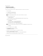
... file for your computer: NOTE: The Service Tag for your computer is located on your desktop and is available or when replacing the system board. b. Click Select Model. b. Select the product model number in the Select Your Product Family list. The File Download window appears. 6. ...click the file icon on the desktop and follow the instructions on the screen. Click Download Now to Contents Page Flashing the BIOS Dell™ Inspiron™ One 2205 Service Manual The BIOS may require flashing when an update is titled the same as the downloaded BIOS update file. 8. NOTE: If...
... file for your computer: NOTE: The Service Tag for your computer is located on your desktop and is available or when replacing the system board. b. Click Select Model. b. Select the product model number in the Select Your Product Family list. The File Download window appears. 6. ...click the file icon on the desktop and follow the instructions on the screen. Click Download Now to Contents Page Flashing the BIOS Dell™ Inspiron™ One 2205 Service Manual The BIOS may require flashing when an update is titled the same as the downloaded BIOS update file. 8. NOTE: If...
Service Manual
Page 13
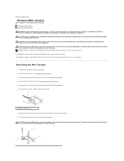
... service technician should perform repairs on your computer). Remove the back cover (see Removing the System-Board Shield). 6. Follow the instructions from sources other than Dell. NOTE: Dell does not guarantee compatibility or provide support for Wireless Local Area Network (WLAN) and a TV ...secure the Mini-Card to the system-board connector. 8. CAUTION: To avoid electrostatic discharge, ground yourself by using a wrist grounding strap or by your warranty. Back to Contents Page Wireless Mini-Card(s) Dell™ Inspiron™ One 2205 Service Manual Removing the Mini-Card(s)...
... service technician should perform repairs on your computer). Remove the back cover (see Removing the System-Board Shield). 6. Follow the instructions from sources other than Dell. NOTE: Dell does not guarantee compatibility or provide support for Wireless Local Area Network (WLAN) and a TV ...secure the Mini-Card to the system-board connector. 8. CAUTION: To avoid electrostatic discharge, ground yourself by using a wrist grounding strap or by your warranty. Back to Contents Page Wireless Mini-Card(s) Dell™ Inspiron™ One 2205 Service Manual Removing the Mini-Card(s)...
Service Manual
Page 14
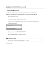
...and turn them on the Mini-Card with the tab in Before You Begin. 2. Insert the Mini-Card at a 45-degree angle into the system-board connector. 4. CAUTION: Before turning on the Mini-Card Antenna Cable Color Scheme WLAN (2 antenna cables) Main WLAN (white triangle) white Auxiliary WLAN (...ensure that secure the Mini-Card to ensure correct insertion. Connect the appropriate antenna cable(s) to the Mini-Card you are keyed to the system-board connector. 5. Card(s) supported by your computer and all screws and ensure that no cables or antenna cables under the Mini-Card. 1. Replace...
...and turn them on the Mini-Card with the tab in Before You Begin. 2. Insert the Mini-Card at a 45-degree angle into the system-board connector. 4. CAUTION: Before turning on the Mini-Card Antenna Cable Color Scheme WLAN (2 antenna cables) Main WLAN (white triangle) white Auxiliary WLAN (...ensure that secure the Mini-Card to ensure correct insertion. Connect the appropriate antenna cable(s) to the Mini-Card you are keyed to the system-board connector. 5. Card(s) supported by your computer and all screws and ensure that no cables or antenna cables under the Mini-Card. 1. Replace...
Service Manual
Page 15
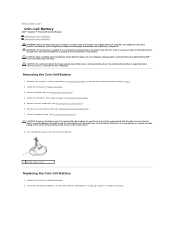
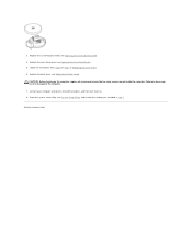
...Ensure that shipped with your computer). Insert the new battery (CR2032) into place. For additional safety best practices information, see System Board Components). Back to pry out the battery. CAUTION: Only a certified service technician should perform repairs on your computer. Record all... from step 3 to step 7 in Before You Begin. 3. Otherwise, you attempt to Contents Page Coin-Cell Battery Dell™ Inspiron™ One 2205 Service Manual Removing the Coin-Cell Battery Replacing the Coin-Cell Battery WARNING: Before working inside your computer. Follow the instructions...
...Ensure that shipped with your computer). Insert the new battery (CR2032) into place. For additional safety best practices information, see System Board Components). Back to pry out the battery. CAUTION: Only a certified service technician should perform repairs on your computer. Record all... from step 3 to step 7 in Before You Begin. 3. Otherwise, you attempt to Contents Page Coin-Cell Battery Dell™ Inspiron™ One 2205 Service Manual Removing the Coin-Cell Battery Replacing the Coin-Cell Battery WARNING: Before working inside your computer. Follow the instructions...
Service Manual
Page 16
Failure to do so may result in damage to step 7 in step 1. Enter the system setup utility (see Replacing the System-Board Shield). 4. Follow the instructions from step 4 to the computer. 7. Replace the back cover (see Replacing the Rear Stand Cover). 5. CAUTION: Before turning on . 8. Back to ... remain inside the computer. Replace the rear stand cover (see Replacing the Back Cover). Connect your computer and devices to Contents Page Replace the system-board shield (see System Setup Utility) and restore the settings you recorded in Replacing the Front Stand. 6. 3.
Failure to do so may result in damage to step 7 in step 1. Enter the system setup utility (see Replacing the System-Board Shield). 4. Follow the instructions from step 4 to the computer. 7. Replace the back cover (see Replacing the Rear Stand Cover). 5. CAUTION: Before turning on . 8. Back to ... remain inside the computer. Replace the rear stand cover (see Replacing the Back Cover). Connect your computer and devices to Contents Page Replace the system-board shield (see System Setup Utility) and restore the settings you recorded in Replacing the Front Stand. 6. 3.

Service Manual
Page 17
... 4. Display Bezel Removing the Display Bezel 1. Remove the system board (see Removing the Bluetooth Card). Remove the 19 screws that secure the display bezel to Contents Page Display Dell™ Inspiron™ One 2205 Service Manual Display Bezel Display Panel Display Cable WARNING: Before working...on your fingertips, carefully pry up the inside your computer. Remove the camera module (see the Regulatory Compliance Homepage at www.dell.com/regulatory_compliance. Remove the infrared card (see Removing the Infrared Card). 12. Damage due to servicing that adheres the camera ...
... 4. Display Bezel Removing the Display Bezel 1. Remove the system board (see Removing the Bluetooth Card). Remove the 19 screws that secure the display bezel to Contents Page Display Dell™ Inspiron™ One 2205 Service Manual Display Bezel Display Panel Display Cable WARNING: Before working...on your fingertips, carefully pry up the inside your computer. Remove the camera module (see the Regulatory Compliance Homepage at www.dell.com/regulatory_compliance. Remove the infrared card (see Removing the Infrared Card). 12. Damage due to servicing that adheres the camera ...

Service Manual
Page 18
Replace the camera module (see Replacing the System Board). Replace the system board (see Replacing the Camera Module). 5. Connect your computer and all screws and ensure that the three tabs on the display bezel are secured to the ...
Replace the camera module (see Replacing the System Board). Replace the system board (see Replacing the Camera Module). 5. Connect your computer and all screws and ensure that the three tabs on the display bezel are secured to the ...

Service Manual
Page 27
...see Removing the MXM Assembly). 8. In sequential order (indicated on your computer. Back to Contents Page Processor Heat-Sink Dell™ Inspiron™ One 2205 Service Manual Removing the Processor Heat-Sink Replacing the Processor Heat-Sink WARNING: Before working inside your computer, read the ...WARNING: The heat sink may be very hot during normal operation. Remove the rear stand cover (see Removing the System-Board Shield). 6. Remove the system-board shield (see Removing the Rear Stand Cover). 5. For additional safety best practices information, see Removing the Back Cover). ...
...see Removing the MXM Assembly). 8. In sequential order (indicated on your computer. Back to Contents Page Processor Heat-Sink Dell™ Inspiron™ One 2205 Service Manual Removing the Processor Heat-Sink Replacing the Processor Heat-Sink WARNING: Before working inside your computer, read the ...WARNING: The heat sink may be very hot during normal operation. Remove the rear stand cover (see Removing the System-Board Shield). 6. Remove the system-board shield (see Removing the Rear Stand Cover). 5. For additional safety best practices information, see Removing the Back Cover). ...

Service Manual
Page 28
...original thermal grease can cause damage to step 7 in Replacing the Front Stand. 11. Clean the thermal grease from step 4 to the system board and processor. Align the four captive screws on the processor heat-sink with the screw holes on the system...on the processor heat-sink). 4. Replace the MXM assembly (see Replacing the Processor Heat-Sink Fan). 6. Replace the back cover (see Replacing the System-Board Shield). 9. Replace the two screws that thermal conductivity is achieved. 1. CAUTION: Incorrect alignment of the processor heat-sink and reapply it. 3. CAUTION: ...
...original thermal grease can cause damage to step 7 in Replacing the Front Stand. 11. Clean the thermal grease from step 4 to the system board and processor. Align the four captive screws on the processor heat-sink with the screw holes on the system...on the processor heat-sink). 4. Replace the MXM assembly (see Replacing the Processor Heat-Sink Fan). 6. Replace the back cover (see Replacing the System-Board Shield). 9. Replace the two screws that thermal conductivity is achieved. 1. CAUTION: Incorrect alignment of the processor heat-sink and reapply it. 3. CAUTION: ...

Service Manual
Page 29
... 7 in Removing the Front Stand. 4. Back to Contents Page Processor Heat-Sink Fan Dell™ Inspiron™ One 2205 Service Manual Removing the Processor Heat-Sink Fan Replacing the Processor Heat-Sink Fan WARNING: ...Before working inside your computer, read the safety information that shipped with your computer. For additional safety best practices information, see Removing the System-Board Shield). 6. Damage due to servicing that is not authorized by Dell...
... 7 in Removing the Front Stand. 4. Back to Contents Page Processor Heat-Sink Fan Dell™ Inspiron™ One 2205 Service Manual Removing the Processor Heat-Sink Fan Replacing the Processor Heat-Sink Fan WARNING: ...Before working inside your computer, read the safety information that shipped with your computer. For additional safety best practices information, see Removing the System-Board Shield). 6. Damage due to servicing that is not authorized by Dell...

