
Owner's Manual
Page 3
Contents Finding Information 11 1 Setting Up and Using Your Computer . . . 15 Front View of the Computer 15 Inspiron 530/530a/530c 15 Inspiron 530b/530d 17 Back View of the Computer 19 Inspiron 530/530a/530c 19 Inspiron 530b/530d 21 Back Panel Connectors 22 Inspiron 530/530a/530c 22 Inspiron 530b/530d 25 Installing Your Computer in an Enclosure 27 Setting Up a Printer 29 Printer Cable 29 Connecting a USB Printer 29 Playing CDs and DVDs 31 Adjusting the Volume 32 Configuring the Audio Connectors for 5.1-Channel 33 Adjusting the Picture 33 Contents 3
Contents Finding Information 11 1 Setting Up and Using Your Computer . . . 15 Front View of the Computer 15 Inspiron 530/530a/530c 15 Inspiron 530b/530d 17 Back View of the Computer 19 Inspiron 530/530a/530c 19 Inspiron 530b/530d 21 Back Panel Connectors 22 Inspiron 530/530a/530c 22 Inspiron 530b/530d 25 Installing Your Computer in an Enclosure 27 Setting Up a Printer 29 Printer Cable 29 Connecting a USB Printer 29 Playing CDs and DVDs 31 Adjusting the Volume 32 Configuring the Audio Connectors for 5.1-Channel 33 Adjusting the Picture 33 Contents 3

Owner's Manual
Page 7
...Dell Factory Image Restore 100 Using the Operating System CD 103 4 Removing and Installing Parts 105 Before You Begin 105 Recommended Tools 105 Turning Off Your Computer 106 Before Working Inside Your Computer 106 Removing the Computer Cover 107 Inside View of Your Computer 109 System Board Components 110 Inspiron 530 110 Inspiron... 530a 112 Inspiron 530b 114 Inspiron 530c 116 Inspiron 530d 118 Contents 7
...Dell Factory Image Restore 100 Using the Operating System CD 103 4 Removing and Installing Parts 105 Before You Begin 105 Recommended Tools 105 Turning Off Your Computer 106 Before Working Inside Your Computer 106 Removing the Computer Cover 107 Inside View of Your Computer 109 System Board Components 110 Inspiron 530 110 Inspiron... 530a 112 Inspiron 530b 114 Inspiron 530c 116 Inspiron 530d 118 Contents 7

Owner's Manual
Page 9
... 167 Processor 168 Removing the Processor 168 Installing the Processor 170 Chassis Fan 172 Removing the Chassis Fan 172 Replacing the Chassis Fan 173 System Board 174 Removing the System Board 174 Installing the System Board 176 Replacing the Computer Cover 176 A Appendix 179 Specifications 179 Inspiron 530/530a/530c 179 Inspiron 530b/530d 182 Inspiron 530/530a...
... 167 Processor 168 Removing the Processor 168 Installing the Processor 170 Chassis Fan 172 Removing the Chassis Fan 172 Replacing the Chassis Fan 173 System Board 174 Removing the System Board 174 Installing the System Board 176 Replacing the Computer Cover 176 A Appendix 179 Specifications 179 Inspiron 530/530a/530c 179 Inspiron 530b/530d 182 Inspiron 530/530a...

Owner's Manual
Page 10
Only 200 FCC Class B 200 Contacting Dell 202 Glossary 203 Index 219 10 Contents Clearing Forgotten Passwords 193 Inspiron 530 193 Inspiron 530a 194 Inspiron 530b 194 Inspiron 530c 195 Inspiron 530d 195 Clearing CMOS Settings 196 Flashing the BIOS 197 Cleaning Your Computer 198 Computer, Keyboard, and Monitor 198 Mouse 198 Floppy Drive (Optional 199 CDs and DVDs 199 Dell Technical Support Policy (U.S. Only 199 Definition of "Dell-Installed" Software and Peripherals 200 Definition of "Third-Party" Software and Peripherals 200 FCC Notice (U.S.
Only 200 FCC Class B 200 Contacting Dell 202 Glossary 203 Index 219 10 Contents Clearing Forgotten Passwords 193 Inspiron 530 193 Inspiron 530a 194 Inspiron 530b 194 Inspiron 530c 195 Inspiron 530d 195 Clearing CMOS Settings 196 Flashing the BIOS 197 Cleaning Your Computer 198 Computer, Keyboard, and Monitor 198 Mouse 198 Floppy Drive (Optional 199 CDs and DVDs 199 Dell Technical Support Policy (U.S. Only 199 Definition of "Dell-Installed" Software and Peripherals 200 Definition of "Third-Party" Software and Peripherals 200 FCC Notice (U.S.

Owner's Manual
Page 11
only) • Safety instructions • Regulatory information • Ergonomics information • End User License Agreement Find it Here Dell™ Product Information Guide • How to set up my computer Setup Diagram • Model Number See the back of your computer. ... Are You Looking For? • Warranty information • Terms and Conditions (U.S. NOTE: If there is no label present, the model number is Inspiron 530. Finding Information NOTE: Some features or media may be available in certain countries. Some features or media may not be optional and may not ship...
only) • Safety instructions • Regulatory information • Ergonomics information • End User License Agreement Find it Here Dell™ Product Information Guide • How to set up my computer Setup Diagram • Model Number See the back of your computer. ... Are You Looking For? • Warranty information • Terms and Conditions (U.S. NOTE: If there is no label present, the model number is Inspiron 530. Finding Information NOTE: Some features or media may be available in certain countries. Some features or media may not be optional and may not ship...

Owner's Manual
Page 15
Setting Up and Using Your Computer Front View of the Computer Inspiron 530/530a/530c 1 2 14 3 4 5 13 6 12 7 8 11 9 10 Setting Up and Using Your Computer 15
Setting Up and Using Your Computer Front View of the Computer Inspiron 530/530a/530c 1 2 14 3 4 5 13 6 12 7 8 11 9 10 Setting Up and Using Your Computer 15

Owner's Manual
Page 19
12 microphone connector 13 FlexBay drive 14 CD/DVD drive panel Use the microphone connector to attach a personal computer microphone for voice or musical input into a sound or telephony program. This panel covers the CD/DVD drive. (Shown in open position) Back View of the Computer Inspiron 530/530a/530c 1 2 3 7 4 6 5 Setting Up and Using Your Computer 19 On computers with a sound card, the microphone connector is on the card. Can contain an optional floppy drive or optional Media Card Reader.
12 microphone connector 13 FlexBay drive 14 CD/DVD drive panel Use the microphone connector to attach a personal computer microphone for voice or musical input into a sound or telephony program. This panel covers the CD/DVD drive. (Shown in open position) Back View of the Computer Inspiron 530/530a/530c 1 2 3 7 4 6 5 Setting Up and Using Your Computer 19 On computers with a sound card, the microphone connector is on the card. Can contain an optional floppy drive or optional Media Card Reader.
Owner's Manual
Page 22
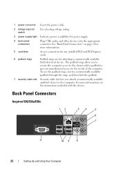
... lock the padlock. 7 security cable slot Security cable slot lets you to secure the computer cover to the chassis with the device. Back Panel Connectors Inspiron 530/530a/530c 12 34 5 6 7 11 10 9 8 22 Setting Up and Using Your Computer See "Back Panel Connectors" on page 22for more information, see the instructions...
... lock the padlock. 7 security cable slot Security cable slot lets you to secure the computer cover to the chassis with the device. Back Panel Connectors Inspiron 530/530a/530c 12 34 5 6 7 11 10 9 8 22 Setting Up and Using Your Computer See "Back Panel Connectors" on page 22for more information, see the instructions...
Owner's Manual
Page 110
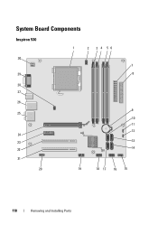
System Board Components Inspiron 530 1 2 3 4 56 30 7 29 8 28 27 26 9 25 10 11 12 24 23 13 22 14 21 20 19 18 17 16 15 110 Removing and Installing Parts
System Board Components Inspiron 530 1 2 3 4 56 30 7 29 8 28 27 26 9 25 10 11 12 24 23 13 22 14 21 20 19 18 17 16 15 110 Removing and Installing Parts
Owner's Manual
Page 124
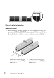
If a single DIMM is installed, you must be populated in connectors DIMM_2 and DIMM_3 and DIMM_4 124 Removing and Installing Parts Memory Installation Guidelines Inspiron 530/530a/530c • DIMM connectors must install it in connector DIMM_1. 1 2 1 Pair A: matched pair of memory 2 Pair B: matched pair of memory modules in connectors DIMM_1 modules in numerical order beginning with connectors DIMM_1 and DIMM_3, then connectors DIMM_2 and DIMM_4.
If a single DIMM is installed, you must be populated in connectors DIMM_2 and DIMM_3 and DIMM_4 124 Removing and Installing Parts Memory Installation Guidelines Inspiron 530/530a/530c • DIMM connectors must install it in connector DIMM_1. 1 2 1 Pair A: matched pair of memory 2 Pair B: matched pair of memory modules in connectors DIMM_1 modules in numerical order beginning with connectors DIMM_1 and DIMM_3, then connectors DIMM_2 and DIMM_4.
Owner's Manual
Page 126
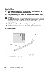
... memory, you must remove the PCI Express x16 card. NOTICE: To prevent static damage to components inside your computer, discharge static electricity from processor (DIMM_1) 2 securing clips (2) 3 connector 126 Removing and Installing Parts You can do so by touching an unpainted metal surface on the computer... chassis. 1 Follow the procedures in the Product Information Guide. Inspiron 530/530a/530c 1 2 3 1 memory connector closest from your body before you touch any of the procedures in this section, follow the safety...
... memory, you must remove the PCI Express x16 card. NOTICE: To prevent static damage to components inside your computer, discharge static electricity from processor (DIMM_1) 2 securing clips (2) 3 connector 126 Removing and Installing Parts You can do so by touching an unpainted metal surface on the computer... chassis. 1 Follow the procedures in the Product Information Guide. Inspiron 530/530a/530c 1 2 3 1 memory connector closest from your body before you touch any of the procedures in this section, follow the safety...

Owner's Manual
Page 175
System Board Screws Inspiron 530/530a/530c 1 2 Inspiron 530b/530d 1 screws (8) 2 system board 1 2 1 screws (6) 2 system board Removing and Installing Parts 175
System Board Screws Inspiron 530/530a/530c 1 2 Inspiron 530b/530d 1 screws (8) 2 system board 1 2 1 screws (6) 2 system board Removing and Installing Parts 175
Owner's Manual
Page 179
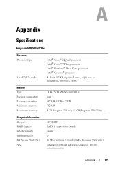
Appendix Specifications Inspiron 530/530a/530c Processor Processor type Level 2 (L2) cache Intel® Core™ 2 Quad processor Intel® Core™ 2 Duo processor Intel® Pentium® Dual-Core processor Intel® Celeron® processor At least 512 KB pipelined-burst, eight-way set associative, writeback SRAM Memory Type Memory connectors Memory capacities Minimum memory Maximum memory DDR2 SDRAM(667/...
Appendix Specifications Inspiron 530/530a/530c Processor Processor type Level 2 (L2) cache Intel® Core™ 2 Quad processor Intel® Core™ 2 Duo processor Intel® Pentium® Dual-Core processor Intel® Celeron® processor At least 512 KB pipelined-burst, eight-way set associative, writeback SRAM Memory Type Memory connectors Memory capacities Minimum memory Maximum memory DDR2 SDRAM(667/...

Owner's Manual
Page 181
... or combo drive (optional) one 3.5-inch floppy drive (optional) or Media Card Reader (optional) NOTE: Floppy drive is supported only on Inspiron 530. 15-hole connector RJ-45 connector two front-panel and four back-panel USB 2.0-compliant connectors six connectors for 7.1 support System board connectors:... Serial ATA four 7-pin connectors Internal USB device two 9-pin connector (supports one flexbay device) Floppy drive one 34-pin connector Processor fan one 4-pin connector Chassis fan one 3-pin connector PCI 2.3 two 124-pin connectors PCI Express x1 one 36-pin connector PCI...
... or combo drive (optional) one 3.5-inch floppy drive (optional) or Media Card Reader (optional) NOTE: Floppy drive is supported only on Inspiron 530. 15-hole connector RJ-45 connector two front-panel and four back-panel USB 2.0-compliant connectors six connectors for 7.1 support System board connectors:... Serial ATA four 7-pin connectors Internal USB device two 9-pin connector (supports one flexbay device) Floppy drive one 34-pin connector Processor fan one 4-pin connector Chassis fan one 3-pin connector PCI 2.3 two 124-pin connectors PCI Express x1 one 36-pin connector PCI...
Owner's Manual
Page 185
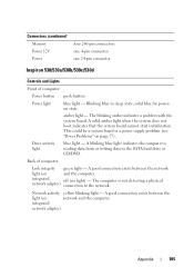
... state amber light - Blinking blue in sleep state; Connectors (continued) Memory Power 12V Power four 240-pin connectors one 4-pin connector one 24-pin connector Inspiron 530/530a/530b/530c/530d Controls and Lights Front of computer: Link integrity green light -
... state amber light - Blinking blue in sleep state; Connectors (continued) Memory Power 12V Power four 240-pin connectors one 4-pin connector one 24-pin connector Inspiron 530/530a/530b/530c/530d Controls and Lights Front of computer: Link integrity green light -

Owner's Manual
Page 191
... to a USB device, the device must be bootable. The BIOS detects the device and adds the USB flash option to change the boot sequence for Inspiron 530, 530a and 530c only. Appendix 191 Last (Off by default) Boot Sequence This feature allows you to the boot menu. SATA Mode IDE; On...
... to a USB device, the device must be bootable. The BIOS detects the device and adds the USB flash option to change the boot sequence for Inspiron 530, 530a and 530c only. Appendix 191 Last (Off by default) Boot Sequence This feature allows you to the boot menu. SATA Mode IDE; On...

Owner's Manual
Page 193
Inspiron 530 Appendix 193 NOTE: The location of the procedures in this section, follow the safety instructions located in the Product Information Guide. 1 Follow the procedures in "Before You Begin" on page 105. 2 Remove the computer cover (see "Removing the Computer Cover" on page 107). 3 Locate the 3-pin password connector (PSWD) on the system. Clearing Forgotten Passwords CAUTION: Before you begin any of the password connector may vary depending on the system board.
Inspiron 530 Appendix 193 NOTE: The location of the procedures in this section, follow the safety instructions located in the Product Information Guide. 1 Follow the procedures in "Before You Begin" on page 105. 2 Remove the computer cover (see "Removing the Computer Cover" on page 107). 3 Locate the 3-pin password connector (PSWD) on the system. Clearing Forgotten Passwords CAUTION: Before you begin any of the password connector may vary depending on the system board.

Owner's Manual
Page 196
... the network device and then plug it into the computer. 8 Connect your computer model: • "Inspiron 530" on page 193 • "Inspiron 530a" on page 194 • "Inspiron 530b" on page 194 • "Inspiron 530c" on page 195 • "Inspiron 530d" on page 176). Clearing CMOS Settings CAUTION: Before you begin any of the procedures in...
... the network device and then plug it into the computer. 8 Connect your computer model: • "Inspiron 530" on page 193 • "Inspiron 530a" on page 194 • "Inspiron 530b" on page 194 • "Inspiron 530c" on page 195 • "Inspiron 530d" on page 176). Clearing CMOS Settings CAUTION: Before you begin any of the procedures in...
Owner's Manual
Page 201
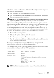
...These limits are designed to operate this document in compliance with the FCC regulations: Product name: Model number: Company name: Dell™ Inspiron™ 530 Series DCMF Dell Inc. If necessary, consult a representative of the following two conditions: 1 This device may not cause harmful interference. ...this equipment. The following information is provided on different branch circuits. This device complies with respect to correct the interference by Dell Inc. However, there is subject to the following measures: • Reorient the receiving antenna. • Relocate the ...
...These limits are designed to operate this document in compliance with the FCC regulations: Product name: Model number: Company name: Dell™ Inspiron™ 530 Series DCMF Dell Inc. If necessary, consult a representative of the following two conditions: 1 This device may not cause harmful interference. ...this equipment. The following information is provided on different branch circuits. This device complies with respect to correct the interference by Dell Inc. However, there is subject to the following measures: • Reorient the receiving antenna. • Relocate the ...


