Service Manual
Page 4
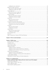
... Screw list...52 Major components of Inspiron 3020 Small Desktop 52 Chapter 3: Drivers and downloads 55 Chapter 4: BIOS setup...56 Entering BIOS setup program...56 Navigation keys...56 One time boot menu...56 System setup options...57 Updating the BIOS...66 Updating the BIOS in Windows...66 Updating the BIOS using the USB drive in Windows 67 Updating the BIOS from the F12 One-Time boot menu 67 System and setup password...68 Assigning a system setup password...68 Deleting or changing an existing system setup password 69 Clearing CMOS settings...69 Clearing BIOS (System Setup...
... Screw list...52 Major components of Inspiron 3020 Small Desktop 52 Chapter 3: Drivers and downloads 55 Chapter 4: BIOS setup...56 Entering BIOS setup program...56 Navigation keys...56 One time boot menu...56 System setup options...57 Updating the BIOS...66 Updating the BIOS in Windows...66 Updating the BIOS using the USB drive in Windows 67 Updating the BIOS from the F12 One-Time boot menu 67 System and setup password...68 Assigning a system setup password...68 Deleting or changing an existing system setup password 69 Clearing CMOS settings...69 Clearing BIOS (System Setup...

Service Manual
Page 6
... eject any installed card from all power sources before disconnecting the cable. When connecting cables, ensure that shipped with the product or at www.dell.com/ regulatory_compliance. NOTE: The color of the computer. Save and close all open applications. 2. After you finish working inside the computer, replace all open files and exit all covers, panels, and screws before connecting your computer. For Windows operating system, click Start > Power > Shut...
... eject any installed card from all power sources before disconnecting the cable. When connecting cables, ensure that shipped with the product or at www.dell.com/ regulatory_compliance. NOTE: The color of the computer. Save and close all open applications. 2. After you finish working inside the computer, replace all open files and exit all covers, panels, and screws before connecting your computer. For Windows operating system, click Start > Power > Shut...

Service Manual
Page 7
... you remove all attached devices from their electrical outlets. 4. Working inside any tabletnotebookdesktop to avoid electrostatic discharge (ESD) damage. ● After removing any disassembly instructions. Disconnect all network cables, telephone, and telecommunications lines from the network device. 5. Observe the following safety precautions before you perform any media card and optical disc from your computer. Unplugging, pressing and holding the power button for 15 seconds should be remotely turned on (wake...
... you remove all attached devices from their electrical outlets. 4. Working inside any tabletnotebookdesktop to avoid electrostatic discharge (ESD) damage. ● After removing any disassembly instructions. Disconnect all network cables, telephone, and telecommunications lines from the network device. 5. Observe the following safety precautions before you perform any media card and optical disc from your computer. Unplugging, pressing and holding the power button for 15 seconds should be remotely turned on (wake...

Service Manual
Page 9
... your back upright, whether lifting or setting down . Replace all times when servicing Dell products. Turn on your computer 9 Connect any other parts that no stray screws remain inside your computer. 3. If the recovery key is not suspended before updating the BIOS, the next time you reboot the system it is recommended to use a mechanical lifting device. 1. The installation of the load. 3. In addition, it will...
... your back upright, whether lifting or setting down . Replace all times when servicing Dell products. Turn on your computer 9 Connect any other parts that no stray screws remain inside your computer. 3. If the recovery key is not suspended before updating the BIOS, the next time you reboot the system it is recommended to use a mechanical lifting device. 1. The installation of the load. 3. In addition, it will...

Service Manual
Page 45
... on the processor socket. 3. Prerequisites 1. Remove the memory. 7. Remove the fan shroud. 12. Close the processor cover. 5. Install the fan and heat-sink assembly. 2. Follow the procedure in After working inside your computer is intended for authorized service technicians only. System board Removing the system board CAUTION: The information in Before working inside your computer. 2. Remove the wireless card. 9. Install the fan shroud. 3. Remove the hard-drive and optical-drive cage. 6. NOTE: Replacing the system board removes any changes that you...
... on the processor socket. 3. Prerequisites 1. Remove the memory. 7. Remove the fan shroud. 12. Close the processor cover. 5. Install the fan and heat-sink assembly. 2. Follow the procedure in After working inside your computer is intended for authorized service technicians only. System board Removing the system board CAUTION: The information in Before working inside your computer. 2. Remove the wireless card. 9. Install the fan shroud. 3. Remove the hard-drive and optical-drive cage. 6. NOTE: Replacing the system board removes any changes that you...

Service Manual
Page 46
M.2 wireless-card slot 11. Hard-drive and optical-drive power cable connector (SATA PWR) 13. PCIe x1 slot (SLOT1) 16. Processor socket 3. Processor-power cable connector (ATX CPU2) 4. M.2 2230/2280 solid-state drive slot 7. Optical-drive data cable connector (SATA-3) 12. Hard-drive data cable connector (SATA-0, boot drive) 14. Memory module slots 6. Processor-fan cable connector 5. 1. Media-card reader cable connector 9. System-board power cable connector (ATX SYS) 10. PCIe x16 slot (SLOT2) 15. Coin-cell battery socket The following images indicate the location of ...
M.2 wireless-card slot 11. Hard-drive and optical-drive power cable connector (SATA PWR) 13. PCIe x1 slot (SLOT1) 16. Processor socket 3. Processor-power cable connector (ATX CPU2) 4. M.2 2230/2280 solid-state drive slot 7. Optical-drive data cable connector (SATA-3) 12. Hard-drive data cable connector (SATA-0, boot drive) 14. Memory module slots 6. Processor-fan cable connector 5. 1. Media-card reader cable connector 9. System-board power cable connector (ATX SYS) 10. PCIe x16 slot (SLOT2) 15. Coin-cell battery socket The following images indicate the location of ...

Service Manual
Page 49
...Optical-drive data cable connector (SATA-3) 12. PCIe x16 slot (SLOT2) 15. M.2 wireless-card slot 11. 1. Memory module slots 6. Coin-cell battery socket The following images indicate the location of the system board and provide a visual representation of the installation procedure. Hard-drive and optical-drive power cable connector (SATA PWR) 13. Processor-fan cable connector 5. Power-button cable connector 8. System-board power cable connector (ATX SYS) 10. Processor-power cable connector (ATX CPU2) 4. Hard-drive data cable connector (SATA-0, boot drive) 14. PCIe x1 slot...
...Optical-drive data cable connector (SATA-3) 12. PCIe x16 slot (SLOT2) 15. M.2 wireless-card slot 11. 1. Memory module slots 6. Coin-cell battery socket The following images indicate the location of the system board and provide a visual representation of the installation procedure. Hard-drive and optical-drive power cable connector (SATA PWR) 13. Processor-fan cable connector 5. Power-button cable connector 8. System-board power cable connector (ATX SYS) 10. Processor-power cable connector (ATX CPU2) 4. Hard-drive data cable connector (SATA-0, boot drive) 14. PCIe x1 slot...

Service Manual
Page 51
... cables to secure the front I /O slot on the chassis. Route and connect the following tools: ● Philips screwdriver #1 and #2 Removing and installing components 51 Install the processor. 2. Install the left-side cover. 13. Align and place the front I/O bracket with the rear external ports aligned to secure the system board on the chassis. 4. Install the media-card reader. 5. Install the fan shroud. 4. Install the wireless card. 7. Recommended tools The procedures in After working inside...
... cables to secure the front I /O slot on the chassis. Route and connect the following tools: ● Philips screwdriver #1 and #2 Removing and installing components 51 Install the processor. 2. Install the left-side cover. 13. Align and place the front I/O bracket with the rear external ports aligned to secure the system board on the chassis. 4. Install the media-card reader. 5. Install the fan shroud. 4. Install the wireless card. 7. Recommended tools The procedures in After working inside...

Service Manual
Page 52
... the screw type, the quantity of Inspiron 3020 Small Desktop. 52 Removing and installing components Screw list NOTE: When removing screws from a component, it is recommended to Chassis Screw type #6-32 Quantity 2 Screw image 2230 solid-state drive System board 2280 solid-state drive System board Wireless card System board 2.5-inch hard drive Chassis 3.5-inch hard drive Chassis Power supply unit Chassis M2x3 1 M2x3 1 M2x3 1 #6-32 1 M3x4 4 #6-32 2 2 #6-32, hex head 3 Optical drive (optional) Chassis Media-card reader (optional) Chassis Processor fan and...
... the screw type, the quantity of Inspiron 3020 Small Desktop. 52 Removing and installing components Screw list NOTE: When removing screws from a component, it is recommended to Chassis Screw type #6-32 Quantity 2 Screw image 2230 solid-state drive System board 2280 solid-state drive System board Wireless card System board 2.5-inch hard drive Chassis 3.5-inch hard drive Chassis Power supply unit Chassis M2x3 1 M2x3 1 M2x3 1 #6-32 1 M3x4 4 #6-32 2 2 #6-32, hex head 3 Optical drive (optional) Chassis Media-card reader (optional) Chassis Processor fan and...

Service Manual
Page 56
... computer, such as the user password, type of hard drive installed, and enabling or disabling base devices. Selects a value in the selected field (if applicable) or follow the link in the main screen displays a message that you write down list, if applicable. One time boot menu To enter one time boot menu, turn on . 56 BIOS setup 4 BIOS setup CAUTION: Unless you are recorded but do not change a user-selectable option, such as the amount...
... computer, such as the user password, type of hard drive installed, and enabling or disabling base devices. Selects a value in the selected field (if applicable) or follow the link in the main screen displays a message that you write down list, if applicable. One time boot menu To enter one time boot menu, turn on . 56 BIOS setup 4 BIOS setup CAUTION: Unless you are recorded but do not change a user-selectable option, such as the amount...

Service Manual
Page 58
... operation of UEFI driver signatures. Video BIOS Version Displays the video BIOS version of the computer. Audio Controller Displays the audio controller information of the computer. By default, Windows Boot Manager is selected By default, UEFI Hard Drive is selected By default, ONBOARD NIC (IPV4) is selected By default, ONBOARD NIC (IPV6) is selected By default, UEFI HTTPS Boost is selected. By default, Deployed Mode is selected Secure Boot Enable Secure Boot Enables secure boot using only validated boot software. Expert Key Management Enable Custom Mode...
... operation of UEFI driver signatures. Video BIOS Version Displays the video BIOS version of the computer. Audio Controller Displays the audio controller information of the computer. By default, Windows Boot Manager is selected By default, UEFI Hard Drive is selected By default, ONBOARD NIC (IPV4) is selected By default, ONBOARD NIC (IPV6) is selected By default, UEFI HTTPS Boost is selected. By default, Deployed Mode is selected Secure Boot Enable Secure Boot Enables secure boot using only validated boot software. Expert Key Management Enable Custom Mode...

Service Manual
Page 59
... Enables or disables microphone. By default, Front Port 5 (Top Right) is selected. Table 4. System setup options-Integrated Devices menu Integrated Devices Date/Time Date Sets the computer date in the BIOS setup irrespective of this setting. By default, Enable Internal Speaker is selected. USB Configuration Enables or disables booting from a userselected file. ● Delete will delete the selected key. ● Reset All Keys will add a key to the current database from USB mass storage devices such as external hard drive, optical drive, and USB drive. By default, Rear...
... Enables or disables microphone. By default, Front Port 5 (Top Right) is selected. Table 4. System setup options-Integrated Devices menu Integrated Devices Date/Time Date Sets the computer date in the BIOS setup irrespective of this setting. By default, Enable Internal Speaker is selected. USB Configuration Enables or disables booting from a userselected file. ● Delete will delete the selected key. ● Reset All Keys will add a key to the current database from USB mass storage devices such as external hard drive, optical drive, and USB drive. By default, Rear...

Service Manual
Page 60
... screen logo if the screen resolution matches the image of the integrated storage device controller. By default, Enable with PXE is selected. Wireless Device Enable WLAN Enables or disables the internal WLAN device. System setup options-Storage menu Storage SATA Operation SATA/NVMe Operation Configures operating mode of the logo. By default, Secure Digital (SD) Card is configured to support RAID. (Intel® Rapid Restore Technology) Storage Interface Port Enablement Enables or disables the onboard drives. Turn on or off all media cards, or enable or disable the media card...
... screen logo if the screen resolution matches the image of the integrated storage device controller. By default, Enable with PXE is selected. Wireless Device Enable WLAN Enables or disables the internal WLAN device. System setup options-Storage menu Storage SATA Operation SATA/NVMe Operation Configures operating mode of the logo. By default, Secure Digital (SD) Card is configured to support RAID. (Intel® Rapid Restore Technology) Storage Interface Port Enablement Enables or disables the onboard drives. Turn on or off all media cards, or enable or disable the media card...

Service Manual
Page 61
...Internal Speaker is handshaking between the device and PCI Express hub to determine the best ASPM mode supported by the device. Auto Mode will extract Boot URL from Standby, Hibernation, or Power Off state. System setup options-Power menu Power USB Wake Support Enable USB Wake Support Enables USB devices like a mouse or keyboard to select the appropriate processor performance automatically. There is selected. Default: Auto. Default: OFF Deep Sleep Control Deep Sleep Control Configures how aggressive the system is restored. Table 8. System setup options-Connection menu...
...Internal Speaker is handshaking between the device and PCI Express hub to determine the best ASPM mode supported by the device. Auto Mode will extract Boot URL from Standby, Hibernation, or Power Off state. System setup options-Power menu Power USB Wake Support Enable USB Wake Support Enables USB devices like a mouse or keyboard to select the appropriate processor performance automatically. There is selected. Default: Auto. Default: OFF Deep Sleep Control Deep Sleep Control Configures how aggressive the system is restored. Table 8. System setup options-Connection menu...

Service Manual
Page 63
... password support. Default: ON BIOS Recovery from Hard Drive BIOS Recovery from Hard Drive Enables the computer to change the system and hard drive password without the need for the password before the revert is not available for password. System setup options-Passwords menu (continued) Passwords Digit Enforces password restriction that the password must contain at least one digit. Default: OFF NOTE: When disabled, the PSID revert is powered on the user primary hard drive or an external USB key. Default: OFF Minimum Characters Controls the minimum number...
... password support. Default: ON BIOS Recovery from Hard Drive BIOS Recovery from Hard Drive Enables the computer to change the system and hard drive password without the need for the password before the revert is not available for password. System setup options-Passwords menu (continued) Passwords Digit Enforces password restriction that the password must contain at least one digit. Default: OFF NOTE: When disabled, the PSID revert is powered on the user primary hard drive or an external USB key. Default: OFF Minimum Characters Controls the minimum number...

Service Manual
Page 68
... a power-on or reboot. NOTE: System and setup password feature is in Not Set. Steps 1. System and setup password Password type System password Setup password Description Password that you must enter to access and make changes to the BIOS settings of the computer. 2. Assigning a system setup password Prerequisites You can access the data that is displayed. 3. Use the following steps to perform the BIOS update flash process from the F12 menu: CAUTION: Do not turn off state, insert the USB drive...
... a power-on or reboot. NOTE: System and setup password feature is in Not Set. Steps 1. System and setup password Password type System password Setup password Description Password that you must enter to access and make changes to the BIOS settings of the computer. 2. Assigning a system setup password Prerequisites You can access the data that is displayed. 3. Use the following steps to perform the BIOS update flash process from the F12 menu: CAUTION: Do not turn off state, insert the USB drive...

Service Manual
Page 71
... board, power supply, or cabling. Troubleshooting 71 If problem persists, replace the system board. Replace the system board. Flash latest BIOS version. Replace the system board. Confirm that the memory module is installed properly. LED codes Diagnostic light codes 1,1 1,2 2,1 Problem description TPM detection failure Unrecoverable SPI flash failure CPU failure 2,2 Motherboard, covers BIOS corruption or ROM error 2,3 No Memory/RAM detected 2,4 Memory/RAM failure 2,5 Invalid memory installed 2,6 Motherboard/chipset error 3,1 CMOS battery failure 3,2 PCI of Video card...
... board, power supply, or cabling. Troubleshooting 71 If problem persists, replace the system board. Replace the system board. Flash latest BIOS version. Replace the system board. Confirm that the memory module is installed properly. LED codes Diagnostic light codes 1,1 1,2 2,1 Problem description TPM detection failure Unrecoverable SPI flash failure CPU failure 2,2 Motherboard, covers BIOS corruption or ROM error 2,3 No Memory/RAM detected 2,4 Memory/RAM failure 2,5 Invalid memory installed 2,6 Motherboard/chipset error 3,1 CMOS battery failure 3,2 PCI of Video card...

Service Manual
Page 72
... board, power supply, or cabling. The system needs to go through the setup and configuration process again to AC power. For more information about the Dell SupportAssist OS Recovery, see Dell SupportAssist OS Recovery User's Guide at www.dell.com/serviceabilitytools. NOTE: If AC power is unable to boot to the operating system even after you to diagnose hardware issues, repair your computer, back up your files, or restore your custom BIOS setting...
... board, power supply, or cabling. The system needs to go through the setup and configuration process again to AC power. For more information about the Dell SupportAssist OS Recovery, see Dell SupportAssist OS Recovery User's Guide at www.dell.com/serviceabilitytools. NOTE: If AC power is unable to boot to the operating system even after you to diagnose hardware issues, repair your computer, back up your files, or restore your custom BIOS setting...
Setup and Specifications
Page 3
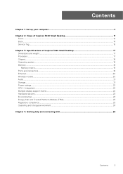
Contents Chapter 1: Set up your computer 4 Chapter 2: Views of Inspiron 3020 Small Desktop 11 Front...12 Back...14 Service Tag...15 Chapter 3: Specifications of Inspiron 3020 Small Desktop 17 Dimensions and weight...17 Processor...17 Chipset...18 Operating system...18 Memory...18 Memory matrix...19 Ports and connectors...19 Ethernet...20 Wireless module...20 Audio...21 Storage...21 Power ratings...22 GPU-Integrated...22 Multiple display support matrix...22 Hardware security...23 Environmental...23 Energy...
Contents Chapter 1: Set up your computer 4 Chapter 2: Views of Inspiron 3020 Small Desktop 11 Front...12 Back...14 Service Tag...15 Chapter 3: Specifications of Inspiron 3020 Small Desktop 17 Dimensions and weight...17 Processor...17 Chipset...18 Operating system...18 Memory...18 Memory matrix...19 Ports and connectors...19 Ethernet...20 Wireless module...20 Audio...21 Storage...21 Power ratings...22 GPU-Integrated...22 Multiple display support matrix...22 Hardware security...23 Environmental...23 Energy...
Setup and Specifications
Page 15
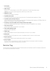
... of Inspiron 3020 Small Desktop 15 Provides video and audio output. Two USB 2.0 ports with the keyboard or mouse connected to 5 Gbps. 5. Views of your computer and access warranty information. Two USB 3.2 Gen 1 ports Connect devices such as external storage devices and printers. Line-out port Connect speakers. 2. HDMI 1.4b port Connect to your computer. 10. Provides data transfer speeds up to this port. 6. Power cable connector Connect a power cable to provide power to a TV, external display or another HDMI-in your computer. 12. Power-supply diagnostics light Indicates...
... of Inspiron 3020 Small Desktop 15 Provides video and audio output. Two USB 2.0 ports with the keyboard or mouse connected to 5 Gbps. 5. Views of your computer and access warranty information. Two USB 3.2 Gen 1 ports Connect devices such as external storage devices and printers. Line-out port Connect speakers. 2. HDMI 1.4b port Connect to your computer. 10. Provides data transfer speeds up to this port. 6. Power cable connector Connect a power cable to provide power to a TV, external display or another HDMI-in your computer. 12. Power-supply diagnostics light Indicates...


