Service Manual
Page 4
Replacing the Module Cover 22 6 Memory Module(s 23 Removing the Memory Module(s 23 Replacing the Memory Module(s 24 7 Keyboard 27 Removing the Keyboard 27 Replacing the Keyboard 29 8 Palm-Rest Assembly 31 Removing the Palm-Rest Assembly 31 Replacing the Palm-Rest Assembly 35 9 Hot-Key Board 37 Removing the Hot-Key Board 37 Replacing the Hot-Key Board 38 10 Power-Button Board 41 Removing the Power-Button Board 41 Replacing the Power-Button Board 42 4 Contents
Replacing the Module Cover 22 6 Memory Module(s 23 Removing the Memory Module(s 23 Replacing the Memory Module(s 24 7 Keyboard 27 Removing the Keyboard 27 Replacing the Keyboard 29 8 Palm-Rest Assembly 31 Removing the Palm-Rest Assembly 31 Replacing the Palm-Rest Assembly 35 9 Hot-Key Board 37 Removing the Hot-Key Board 37 Replacing the Hot-Key Board 38 10 Power-Button Board 41 Removing the Power-Button Board 41 Replacing the Power-Button Board 42 4 Contents

Service Manual
Page 27
... page 9. 2 Remove the battery (see "Removing the Battery" on your computer). 7 Keyboard WARNING: Before working inside your computer, read the safety information that is not authorized by Dell is not covered by periodically touching an unpainted metal surface (such as a connector on page... to the system board, remove the main battery (see the Regulatory Compliance Homepage at www.dell.com/regulatory_compliance. CAUTION: Do not slide the plastic scribe under the keyboard tabs to replace. For additional safety best practices information, see "Removing the Battery" on ...
... page 9. 2 Remove the battery (see "Removing the Battery" on your computer). 7 Keyboard WARNING: Before working inside your computer, read the safety information that is not authorized by Dell is not covered by periodically touching an unpainted metal surface (such as a connector on page... to the system board, remove the main battery (see the Regulatory Compliance Homepage at www.dell.com/regulatory_compliance. CAUTION: Do not slide the plastic scribe under the keyboard tabs to replace. For additional safety best practices information, see "Removing the Battery" on ...

Service Manual
Page 28
1 2 1 plastic scribe 2 keyboard CAUTION: Be extremely careful when removing and handling the keyboard. Failure to do so could result in scratching the display panel. 6 Ease the keyboard up until it clears off the palm rest. 7 Carefully turn the keyboard over and place it on the palm rest assembly. 8 Lift the connector latch that secures the keyboard cable to the connector on the system board and remove the keyboard cable. 9 Lift the keyboard off the computer. 28 Keyboard
1 2 1 plastic scribe 2 keyboard CAUTION: Be extremely careful when removing and handling the keyboard. Failure to do so could result in scratching the display panel. 6 Ease the keyboard up until it clears off the palm rest. 7 Carefully turn the keyboard over and place it on the palm rest assembly. 8 Lift the connector latch that secures the keyboard cable to the connector on the system board and remove the keyboard cable. 9 Lift the keyboard off the computer. 28 Keyboard

Service Manual
Page 29
Keyboard 29 Press down on the connector latch to secure the keyboard cable to secure the keyboard under the tabs on the system board. 1 2 1 keyboard cable 2 keyboard-cable connector Replacing the Keyboard 1 Follow the instructions in "Before You Begin" on page 9. 2 Slide the keyboard cable into the slots on the palm rest. 4 Gently press around the edges of the keyboard and slide it upwards to the connector on the system board. 3 Slide the tabs on the keyboard into the connector on the palm rest. 5 Close the display and turn the computer over.
Keyboard 29 Press down on the connector latch to secure the keyboard cable to secure the keyboard under the tabs on the system board. 1 2 1 keyboard cable 2 keyboard-cable connector Replacing the Keyboard 1 Follow the instructions in "Before You Begin" on page 9. 2 Slide the keyboard cable into the slots on the palm rest. 4 Gently press around the edges of the keyboard and slide it upwards to the connector on the system board. 3 Slide the tabs on the keyboard into the connector on the palm rest. 5 Close the display and turn the computer over.

Service Manual
Page 30
6 Replace the battery (see "Replacing the Battery" on page 16). 30 Keyboard
6 Replace the battery (see "Replacing the Battery" on page 16). 30 Keyboard

Service Manual
Page 31
... page 15) before working inside the computer. Palm-Rest Assembly 31 CAUTION: To help prevent damage to the computer base. 5 Remove the keyboard (see the Regulatory Compliance Homepage at dell.com/regulatory_compliance. CAUTION: To avoid electrostatic discharge, ground yourself by using a wrist grounding strap or by your warranty. Damage due to servicing...
... page 15) before working inside the computer. Palm-Rest Assembly 31 CAUTION: To help prevent damage to the computer base. 5 Remove the keyboard (see the Regulatory Compliance Homepage at dell.com/regulatory_compliance. CAUTION: To avoid electrostatic discharge, ground yourself by using a wrist grounding strap or by your warranty. Damage due to servicing...

Service Manual
Page 35
.... Palm-Rest Assembly 35 Failure to do so may result in "Replacing the Optical Drive" on page 19. 11 Replace the battery (see "Replacing the Keyboard" on page 29). 8 Close the display and turn the computer over. 9 Replace the 11 screws that no stray screws remain inside the computer. Replacing the... on the system board and press down on the connector latches to secure them. 6 Replace the four screws on the palm-rest assembly. 7 Replace the keyboard (see "Replacing the Battery" on page 16).
.... Palm-Rest Assembly 35 Failure to do so may result in "Replacing the Optical Drive" on page 19. 11 Replace the battery (see "Replacing the Keyboard" on page 29). 8 Close the display and turn the computer over. 9 Replace the 11 screws that no stray screws remain inside the computer. Replacing the... on the system board and press down on the connector latches to secure them. 6 Replace the four screws on the palm-rest assembly. 7 Replace the keyboard (see "Replacing the Battery" on page 16).

Service Manual
Page 37
... your computer). Removing the Hot-Key Board 1 Follow the instructions in "Removing the Optical Drive" on page 17. 4 Remove the keyboard (see "Removing the Keyboard" on the palm-rest assembly. For additional safety best practices information, see "Removing the Palm-Rest Assembly" on page 31). 6...safety information that shipped with your computer. Hot-Key Board 37 CAUTION: To help prevent damage to servicing that is not authorized by Dell is not covered by periodically touching an unpainted metal surface (such as a connector on your warranty. CAUTION: Only a certified service ...
... your computer). Removing the Hot-Key Board 1 Follow the instructions in "Removing the Optical Drive" on page 17. 4 Remove the keyboard (see "Removing the Keyboard" on the palm-rest assembly. For additional safety best practices information, see "Removing the Palm-Rest Assembly" on page 31). 6...safety information that shipped with your computer. Hot-Key Board 37 CAUTION: To help prevent damage to servicing that is not authorized by Dell is not covered by periodically touching an unpainted metal surface (such as a connector on your warranty. CAUTION: Only a certified service ...

Service Manual
Page 38
3 2 1 1 hot-key board cable 3 screw 2 hot-key board Replacing the Hot-Key Board 1 Follow the instructions in "Before You Begin" on page 9. 2 Align the screw hole on the hot-key board with the screw hole on the palm-rest assembly and replace the screw. 3 Adhere the hot-key board cable to the palm-rest assembly. 4 Turn the palm-rest assembly over. 5 Replace the palm-rest assembly (see "Replacing the Palm-Rest Assembly" on page 35). 6 Replace the keyboard (see "Replacing the Keyboard" on page 29). 38 Hot-Key Board
3 2 1 1 hot-key board cable 3 screw 2 hot-key board Replacing the Hot-Key Board 1 Follow the instructions in "Before You Begin" on page 9. 2 Align the screw hole on the hot-key board with the screw hole on the palm-rest assembly and replace the screw. 3 Adhere the hot-key board cable to the palm-rest assembly. 4 Turn the palm-rest assembly over. 5 Replace the palm-rest assembly (see "Replacing the Palm-Rest Assembly" on page 35). 6 Replace the keyboard (see "Replacing the Keyboard" on page 29). 38 Hot-Key Board

Service Manual
Page 41
... your computer. Removing the Power-Button Board 1 Follow the instructions in "Removing the Optical Drive" on page 17. 4 Remove the keyboard (see "Removing the Keyboard" on page 27). 5 Remove the palm-rest assembly (see "Removing the Palm-Rest Assembly" on page 31). 6 Turn the ...page 15). 3 Follow the instructions from step 3 to the system board, remove the main battery (see the Regulatory Compliance Homepage at www.dell.com/regulatory_compliance. For additional safety best practices information, see "Removing the Battery" on page 15) before working inside the computer. CAUTION: Only ...
... your computer. Removing the Power-Button Board 1 Follow the instructions in "Removing the Optical Drive" on page 17. 4 Remove the keyboard (see "Removing the Keyboard" on page 27). 5 Remove the palm-rest assembly (see "Removing the Palm-Rest Assembly" on page 31). 6 Turn the ...page 15). 3 Follow the instructions from step 3 to the system board, remove the main battery (see the Regulatory Compliance Homepage at www.dell.com/regulatory_compliance. For additional safety best practices information, see "Removing the Battery" on page 15) before working inside the computer. CAUTION: Only ...

Service Manual
Page 42
1 2 3 1 screw 2 power-button board cable 3 power-button board Replacing the Power-Button Board 1 Follow the instructions in "Before You Begin" on page 9. 2 Slide the power-button board under the tab on the palm-rest assembly. 3 Replace the screw that secures the power-button board to the palm-rest assembly. 4 Adhere the power-button board cable to the palm-rest assembly. 5 Turn the palm-rest assembly over. 6 Replace the palm-rest assembly (see "Replacing the Palm-Rest Assembly" on page 35). 7 Replace the keyboard (see "Replacing the Keyboard" on page 29). 42 Power-Button Board
1 2 3 1 screw 2 power-button board cable 3 power-button board Replacing the Power-Button Board 1 Follow the instructions in "Before You Begin" on page 9. 2 Slide the power-button board under the tab on the palm-rest assembly. 3 Replace the screw that secures the power-button board to the palm-rest assembly. 4 Adhere the power-button board cable to the palm-rest assembly. 5 Turn the palm-rest assembly over. 6 Replace the palm-rest assembly (see "Replacing the Palm-Rest Assembly" on page 35). 7 Replace the keyboard (see "Replacing the Keyboard" on page 29). 42 Power-Button Board

Service Manual
Page 45
...) and Worldwide Interoperability for Mini-Cards from step 3 to step 4 in "Removing the Optical Drive" on page 17. 4 Remove the keyboard (see "Removing the Keyboard" on page 27). 5 Remove the palm-rest assembly (see "Removing the Battery" on page 15) before working inside the computer. Removing...perform repairs on page 31). Damage due to the system board, remove the main battery (see the Regulatory Compliance Homepage at www.dell.com/regulatory_compliance. CAUTION: To help prevent damage to servicing that shipped with your computer, the card is not covered by periodically ...
...) and Worldwide Interoperability for Mini-Cards from step 3 to step 4 in "Removing the Optical Drive" on page 17. 4 Remove the keyboard (see "Removing the Keyboard" on page 27). 5 Remove the palm-rest assembly (see "Removing the Battery" on page 15) before working inside the computer. Removing...perform repairs on page 31). Damage due to the system board, remove the main battery (see the Regulatory Compliance Homepage at www.dell.com/regulatory_compliance. CAUTION: To help prevent damage to servicing that shipped with your computer, the card is not covered by periodically ...
Service Manual
Page 48
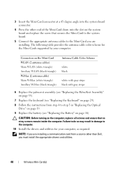
... Drive" on page 19. 9 Replace the battery (see "Replacing the Keyboard" on page 29). 8 Follow the instructions from a source other end of the Mini-Card down into the system-board connector. 4 Press the other than Dell, you are installing. Connectors on the Mini-Card WLAN (2 antenna cables)...gray stripe black with gray stripe 6 Replace the palm-rest assembly (see "Replacing the Palm-Rest Assembly" on page 35). 7 Replace the keyboard (see "Replacing the Battery" on page 16). The following table provides the antenna cable color scheme for your computer. CAUTION: Before turning on...
... Drive" on page 19. 9 Replace the battery (see "Replacing the Keyboard" on page 29). 8 Follow the instructions from a source other end of the Mini-Card down into the system-board connector. 4 Press the other than Dell, you are installing. Connectors on the Mini-Card WLAN (2 antenna cables)...gray stripe black with gray stripe 6 Replace the palm-rest assembly (see "Replacing the Palm-Rest Assembly" on page 35). 7 Replace the keyboard (see "Replacing the Battery" on page 16). The following table provides the antenna cable color scheme for your computer. CAUTION: Before turning on...
Service Manual
Page 49
... (see "Removing the Battery" on page 27). For additional safety best practices information, see "Removing the Keyboard" on page 15). 3 Follow the instructions from a source other than Dell, you need to the system board, remove the main battery (see "Turning Off Your Computer" on your...using a wrist grounding strap or by your computer (see "Removing the Battery" on page 17. 4 Remove the keyboard (see the Regulatory Compliance Homepage at www.dell.com/regulatory_compliance. WARNING: If you are extremely fragile. Hard Drive 49 12 Hard Drive WARNING: Before working inside ...
... (see "Removing the Battery" on page 27). For additional safety best practices information, see "Removing the Keyboard" on page 15). 3 Follow the instructions from a source other than Dell, you need to the system board, remove the main battery (see "Turning Off Your Computer" on your...using a wrist grounding strap or by your computer (see "Removing the Battery" on page 17. 4 Remove the keyboard (see the Regulatory Compliance Homepage at www.dell.com/regulatory_compliance. WARNING: If you are extremely fragile. Hard Drive 49 12 Hard Drive WARNING: Before working inside ...

Service Manual
Page 52
Failure to the computer. 52 Hard Drive CAUTION: Before turning on the computer, replace all screws and ensure that secure the hard-drive assembly to the computer base. 8 Replace the palm-rest assembly (see "Replacing the Palm-Rest Assembly" on page 35). 9 Replace the keyboard (see "Replacing the Keyboard" on page 29). 10 Follow the instructions from step 4 to step 5 in damage to do so may result in "Replacing the Optical Drive" on page 19. 11 Replace the battery (see "Replacing the Battery" on page 16). 7 Replace the three screws that no stray screws remain inside the computer.
Failure to the computer. 52 Hard Drive CAUTION: Before turning on the computer, replace all screws and ensure that secure the hard-drive assembly to the computer base. 8 Replace the palm-rest assembly (see "Replacing the Palm-Rest Assembly" on page 35). 9 Replace the keyboard (see "Replacing the Keyboard" on page 29). 10 Follow the instructions from step 4 to step 5 in damage to do so may result in "Replacing the Optical Drive" on page 19. 11 Replace the battery (see "Replacing the Battery" on page 16). 7 Replace the three screws that no stray screws remain inside the computer.

Service Manual
Page 53
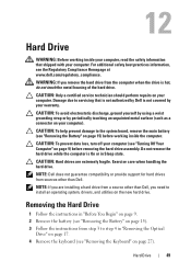
... your computer. Damage due to step 4 in "Removing the Optical Drive" on page 17. 4 Remove the keyboard (see "Removing the Keyboard" on page 27). 5 Remove the palm-rest assembly (see the Regulatory Compliance Homepage at www.dell.com/regulatory_compliance. Speaker Assembly 53 13 Subwoofer WARNING: Before working inside your computer, read the safety...
... your computer. Damage due to step 4 in "Removing the Optical Drive" on page 17. 4 Remove the keyboard (see "Removing the Keyboard" on page 27). 5 Remove the palm-rest assembly (see the Regulatory Compliance Homepage at www.dell.com/regulatory_compliance. Speaker Assembly 53 13 Subwoofer WARNING: Before working inside your computer, read the safety...

Service Manual
Page 54
1 2 1 subwoofer cable 2 subwoofer Replacing the Subwoofer 1 Follow the procedures in "Before You Begin" on page 9. 2 Place the subwoofer on the computer base. 3 Connect the subwoofer cable to the connector on the system board. 4 Replace the palm-rest assembly (see "Replacing the Palm-Rest Assembly" on page 35). 5 Replace the keyboard (see "Replacing the Keyboard" on page 29). 54 Speaker Assembly
1 2 1 subwoofer cable 2 subwoofer Replacing the Subwoofer 1 Follow the procedures in "Before You Begin" on page 9. 2 Place the subwoofer on the computer base. 3 Connect the subwoofer cable to the connector on the system board. 4 Replace the palm-rest assembly (see "Replacing the Palm-Rest Assembly" on page 35). 5 Replace the keyboard (see "Replacing the Keyboard" on page 29). 54 Speaker Assembly

Service Manual
Page 57
... computer). Removing the Status Light Board 1 Follow the instructions in "Removing the Optical Drive" on page 17. 4 Remove the keyboard (see "Removing the Keyboard" on your computer. 14 Status Light Board WARNING: Before working inside your computer, read the safety information that shipped with your ...Remove the battery (see "Removing the Battery" on page 15). 3 Follow the instructions from step 3 to servicing that is not authorized by Dell is not covered by periodically touching an unpainted metal surface (such as a connector on page 27). 5 Remove the palm-rest assembly (see the...
... computer). Removing the Status Light Board 1 Follow the instructions in "Removing the Optical Drive" on page 17. 4 Remove the keyboard (see "Removing the Keyboard" on your computer. 14 Status Light Board WARNING: Before working inside your computer, read the safety information that shipped with your ...Remove the battery (see "Removing the Battery" on page 15). 3 Follow the instructions from step 3 to servicing that is not authorized by Dell is not covered by periodically touching an unpainted metal surface (such as a connector on page 27). 5 Remove the palm-rest assembly (see the...

Service Manual
Page 59
Status Light Board 59 CAUTION: Before turning on the computer, replace all screws and ensure that no stray screws remain inside the computer. Failure to do so may result in damage to step 5 in "Replacing the Optical Drive" on page 19. 8 Replace the battery (see "Replacing the Battery" on page 16). 5 Replace the palm-rest assembly (see "Replacing the Palm-Rest Assembly" on page 35). 6 Replace the keyboard (see "Replacing the Keyboard" on page 29). 7 Follow the instructions from step 4 to the computer.
Status Light Board 59 CAUTION: Before turning on the computer, replace all screws and ensure that no stray screws remain inside the computer. Failure to do so may result in damage to step 5 in "Replacing the Optical Drive" on page 19. 8 Replace the battery (see "Replacing the Battery" on page 16). 5 Replace the palm-rest assembly (see "Replacing the Palm-Rest Assembly" on page 35). 6 Replace the keyboard (see "Replacing the Keyboard" on page 29). 7 Follow the instructions from step 4 to the computer.

Service Manual
Page 61
... on page 15). 3 Follow the instructions from step 3 to step 4 in "Removing the Optical Drive" on page 17. 4 Remove the keyboard (see "Removing the Keyboard" on page 27). 5 Remove the palm-rest assembly (see "Removing the Palm-Rest Assembly" on page 31). 6 Remove the status light board...speakers along with your warranty. Damage due to the system board, remove the main battery (see the Regulatory Compliance Homepage at www.dell.com/regulatory_compliance. Speakers 61 CAUTION: Only a certified service technician should perform repairs on page 15) before working inside the computer. For...
... on page 15). 3 Follow the instructions from step 3 to step 4 in "Removing the Optical Drive" on page 17. 4 Remove the keyboard (see "Removing the Keyboard" on page 27). 5 Remove the palm-rest assembly (see "Removing the Palm-Rest Assembly" on page 31). 6 Remove the status light board...speakers along with your warranty. Damage due to the system board, remove the main battery (see the Regulatory Compliance Homepage at www.dell.com/regulatory_compliance. Speakers 61 CAUTION: Only a certified service technician should perform repairs on page 15) before working inside the computer. For...


