Service Manual
Page 1
.... © 2010 Dell Inc. Trademarks used by Bluetooth SIG, Inc. All rights reserved. Reproduction of Dell Inc. and is a registered trademark owned by Dell under license; Dell™ Inspiron™ N4020/N4030 Service Manual Before You Begin Battery Hard Drive Optical Drive Module Cover Memory Module(s) Keyboard Wireless Mini-Card Palm Rest Power Button Board Display Camera Internal Card With Bluetooth® Wireless Technology System Board Coin-Cell Battery Thermal Cooling Assembly Processor Module I/O Board Speakers Battery Latch Assembly Flashing the BIOS Notes, Cautions...
.... © 2010 Dell Inc. Trademarks used by Bluetooth SIG, Inc. All rights reserved. Reproduction of Dell Inc. and is a registered trademark owned by Dell under license; Dell™ Inspiron™ N4020/N4030 Service Manual Before You Begin Battery Hard Drive Optical Drive Module Cover Memory Module(s) Keyboard Wireless Mini-Card Palm Rest Power Button Board Display Camera Internal Card With Bluetooth® Wireless Technology System Board Coin-Cell Battery Thermal Cooling Assembly Processor Module I/O Board Speakers Battery Latch Assembly Flashing the BIOS Notes, Cautions...

Service Manual
Page 2
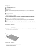
CAUTION: Only a certified service technician should perform repairs on the computer, replace all screws and ensure that secures the module cover to Contents Page Module Cover Dell™ Inspiron™ N4020/N4030 Service Manual Removing the Module Cover Replacing the Module Cover WARNING: Before working inside the computer. CAUTION: Before turning on your computer. Back to the computer base. 4. Follow the instructions in Before You Begin. 2. Removing the Module Cover 1. Follow the instructions in Before...
CAUTION: Only a certified service technician should perform repairs on the computer, replace all screws and ensure that secures the module cover to Contents Page Module Cover Dell™ Inspiron™ N4020/N4030 Service Manual Removing the Module Cover Replacing the Module Cover WARNING: Before working inside the computer. CAUTION: Before turning on your computer. Back to the computer base. 4. Follow the instructions in Before You Begin. 2. Removing the Module Cover 1. Follow the instructions in Before...
Service Manual
Page 5
... operating system: Windows® Vista: Click the Start button Windows® 7: , click the arrow , and then click Shut Down. l You have connectors with your computer. CAUTION: Handle components and cards with your computer. Back to Contents Page Before You Begin Dell™ Inspiron™ N4020/N4030 Service Manual Recommended Tools Turning Off Your Computer Before Working Inside Your Computer This manual provides procedures for removing...
... operating system: Windows® Vista: Click the Start button Windows® 7: , click the arrow , and then click Shut Down. l You have connectors with your computer. CAUTION: Handle components and cards with your computer. Back to Contents Page Before You Begin Dell™ Inspiron™ N4020/N4030 Service Manual Recommended Tools Turning Off Your Computer Before Working Inside Your Computer This manual provides procedures for removing...

Service Manual
Page 8
...If you ordered a card with Bluetooth wireless technology with the connector on your computer, it is already installed. Remove the battery (see Removing the Module Cover). 6. Remove the module cover (see Removing the Battery). 3. CAUTION: To avoid electrostatic discharge, ground yourself by using a wrist grounding strap or by your computer. Remove the memory module(s) (see Removing the Keyboard). 8. Removing the Bluetooth Card 1. Remove the keyboard (see Removing the Memory Module(s)). 7. Follow the instructions from step 3 to step 4 in Removing the Optical Drive...
...If you ordered a card with Bluetooth wireless technology with the connector on your computer, it is already installed. Remove the battery (see Removing the Module Cover). 6. Remove the module cover (see Removing the Battery). 3. CAUTION: To avoid electrostatic discharge, ground yourself by using a wrist grounding strap or by your computer. Remove the memory module(s) (see Removing the Keyboard). 8. Removing the Bluetooth Card 1. Remove the keyboard (see Removing the Memory Module(s)). 7. Follow the instructions from step 3 to step 4 in Removing the Optical Drive...

Service Manual
Page 10
... to the system board, remove the main battery (see Removing the Module Cover). 6. Remove the module cover (see Removing the Battery) before working inside the computer. Follow the instructions from the tabs on the display cover. 13. Slide and lift the camera module to remove it from step 3 to step 4 in Before You Begin. 2. Back to Contents Page Camera Dell™ Inspiron™ N4020/N4030 Service Manual Removing the Camera Replacing the Camera WARNING: Before working inside your...
... to the system board, remove the main battery (see Removing the Module Cover). 6. Remove the module cover (see Removing the Battery) before working inside the computer. Follow the instructions from the tabs on the display cover. 13. Slide and lift the camera module to remove it from step 3 to step 4 in Before You Begin. 2. Back to Contents Page Camera Dell™ Inspiron™ N4020/N4030 Service Manual Removing the Camera Replacing the Camera WARNING: Before working inside your...

Service Manual
Page 17
... to the system board, remove the main battery (see Removing the Module Cover). 6. Remove the keyboard (see the Regulatory Compliance Homepage at www.dell.com/regulatory_compliance. Lift and remove the display assembly out of the computer base. Follow the instructions from step 3 to step 4 in Before You Begin. 2. Back to Contents Page Display Dell™ Inspiron™ N4020/N4030 Service Manual Display Assembly Display Bezel Display Panel WARNING: Before working inside your...
... to the system board, remove the main battery (see Removing the Module Cover). 6. Remove the keyboard (see the Regulatory Compliance Homepage at www.dell.com/regulatory_compliance. Lift and remove the display assembly out of the computer base. Follow the instructions from step 3 to step 4 in Before You Begin. 2. Back to Contents Page Display Dell™ Inspiron™ N4020/N4030 Service Manual Display Assembly Display Bezel Display Panel WARNING: Before working inside your...

Service Manual
Page 18
... Replacing the Display Assembly 1. Route the antenna cables through the routing guides and connect the cables to prevent damaging the bezel. 1. Place the display assembly in Replacing the Hard Drive. 11. Replace the battery (see Replacing the Memory Module(s)). 8. Be careful when removing it to the Mini-Card (see Replacing the Mini-Card). 5. Replace the module cover (see Replacing the Palm Rest). 6. Make a note of the display bezel. 5. Replace the palm rest (see Replacing the Module Cover). 9. Follow the instructions...
... Replacing the Display Assembly 1. Route the antenna cables through the routing guides and connect the cables to prevent damaging the bezel. 1. Place the display assembly in Replacing the Hard Drive. 11. Replace the battery (see Replacing the Memory Module(s)). 8. Be careful when removing it to the Mini-Card (see Replacing the Mini-Card). 5. Replace the module cover (see Replacing the Palm Rest). 6. Make a note of the display bezel. 5. Replace the palm rest (see Replacing the Module Cover). 9. Follow the instructions...
Service Manual
Page 22
... or in Before You Begin. 2. NOTE: Dell does not guarantee compatibility or provide support for hard drives from a source other than Dell, you remove the hard drive from the hard drive. CAUTION: Only a certified service technician should perform repairs on your computer. Damage due to Contents Page Hard Drive Dell™ Inspiron™ N4020/N4030 Service Manual Removing the Hard Drive Replacing the Hard Drive WARNING: Before working inside your computer, read the safety information...
... or in Before You Begin. 2. NOTE: Dell does not guarantee compatibility or provide support for hard drives from a source other than Dell, you remove the hard drive from the hard drive. CAUTION: Only a certified service technician should perform repairs on your computer. Damage due to Contents Page Hard Drive Dell™ Inspiron™ N4020/N4030 Service Manual Removing the Hard Drive Replacing the Hard Drive WARNING: Before working inside your computer, read the safety information...

Service Manual
Page 23
..., as needed . Replace the battery (see the Dell Technology Guide. Failure to do so may result in damage to the computer base. 6. Follow the instructions in the Setup Guide. 8. Install the operating system for storing or shipping the hard drive. 3. See "Restoring Your Operating System" in Before You Begin. 2. Remove the new drive from its packaging. Back to Contents Page Slide the hard-drive assembly into the hard-drive compartment until...
..., as needed . Replace the battery (see the Dell Technology Guide. Failure to do so may result in damage to the computer base. 6. Follow the instructions in the Setup Guide. 8. Install the operating system for storing or shipping the hard drive. 3. See "Restoring Your Operating System" in Before You Begin. 2. Remove the new drive from its packaging. Back to Contents Page Slide the hard-drive assembly into the hard-drive compartment until...

Service Manual
Page 26
... memory module(s) (see Removing the Module Cover). 6. Remove the two screws that is not authorized by Dell™ is not covered by periodically touching an unpainted metal surface (such as possible. Back to Contents Page Keyboard Dell™ Inspiron™ N4020/N4030 Service Manual Removing the Keyboard Replacing the Keyboard WARNING: Before working inside your computer, read the safety information that shipped with your computer). Turn the computer over and open...
... memory module(s) (see Removing the Module Cover). 6. Remove the two screws that is not authorized by Dell™ is not covered by periodically touching an unpainted metal surface (such as possible. Back to Contents Page Keyboard Dell™ Inspiron™ N4020/N4030 Service Manual Removing the Keyboard Replacing the Keyboard WARNING: Before working inside your computer, read the safety information that shipped with your computer). Turn the computer over and open...
Service Manual
Page 29
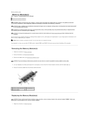
... practices information, see Removing the Battery) before you install a memory module in Before You Begin. 2. CAUTION: Only a certified service technician should perform repairs on the type of the memory-module connector until the module pops up. 5. Follow the instructions in your Setup Guide for information on your computer. Back to Contents Page Memory Module(s) Dell™ Inspiron™ N4020/N4030 Service Manual Removing the Memory Module(s) Replacing the Memory Module(s) WARNING: Before working inside your computer, read...
... practices information, see Removing the Battery) before you install a memory module in Before You Begin. 2. CAUTION: Only a certified service technician should perform repairs on the type of the memory-module connector until the module pops up. 5. Follow the instructions in your Setup Guide for information on your computer. Back to Contents Page Memory Module(s) Dell™ Inspiron™ N4020/N4030 Service Manual Removing the Memory Module(s) Replacing the Memory Module(s) WARNING: Before working inside your computer, read...

Service Manual
Page 30
... turning on the computer. To confirm the amount of memory installed in the memory- Replace the module cover (see Replacing the Battery), or connect the AC adapter to Contents Page Back to your computer and an electrical outlet. Failure to the computer. 6. Align the notch in the memory module with the tab in the computer: Windows® Vista: Click Start Windows® 7: ® Help and Support® Dell System...
... turning on the computer. To confirm the amount of memory installed in the memory- Replace the module cover (see Replacing the Battery), or connect the AC adapter to Contents Page Back to your computer and an electrical outlet. Failure to the computer. 6. Align the notch in the memory module with the tab in the computer: Windows® Vista: Click Start Windows® 7: ® Help and Support® Dell System...
Service Manual
Page 31
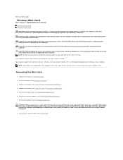
... instructions that shipped with your computer). Damage due to servicing that is not authorized by Dell™ is already installed. NOTE: Dell does not guarantee compatibility or provide support for Microwave Access (WiMax). If you pull connectors apart, keep them . Some cables have Mini-Cards installed in Removing the Hard Drive. 4. As you ordered a wireless Mini-Card with locking tabs; CAUTION: Only a certified service technician should perform repairs on the cable...
... instructions that shipped with your computer). Damage due to servicing that is not authorized by Dell™ is already installed. NOTE: Dell does not guarantee compatibility or provide support for Microwave Access (WiMax). If you pull connectors apart, keep them . Some cables have Mini-Cards installed in Removing the Hard Drive. 4. As you ordered a wireless Mini-Card with locking tabs; CAUTION: Only a certified service technician should perform repairs on the cable...

Service Manual
Page 36
... touch pad cable and the power button cable from step 3 to step 4 in Before You Begin. 2. Remove the battery (see Removing the Memory Module(s)). 7. Follow the instructions from step 3 to the computer base. 8. CAUTION: Only a certified service technician should perform repairs on top of the connectors to avoid damaging the connectors. 9. Remove the module cover (see Removing the Keyboard). Remove the keyboard (see Removing the Module Cover). 6. Back to Contents Page Palm Rest Dell™ Inspiron...
... touch pad cable and the power button cable from step 3 to step 4 in Before You Begin. 2. Remove the battery (see Removing the Memory Module(s)). 7. Follow the instructions from step 3 to the computer base. 8. CAUTION: Only a certified service technician should perform repairs on top of the connectors to avoid damaging the connectors. 9. Remove the module cover (see Removing the Keyboard). Remove the keyboard (see Removing the Module Cover). 6. Back to Contents Page Palm Rest Dell™ Inspiron...

Service Manual
Page 45
... keyboard (see Replacing the Processor Module). 3. 13. Follow the instructions in -1 media card reader. Replace the three screws that no stray screws remain inside the computer. Replace any card or blank removed from the 5-in Before You Begin. 2. NOTE: After you have replaced the system board, enter the computer Service Tag in Replacing the Hard Drive. 17. Lift the system board assembly to step 4 in and that the AC adapter...
... keyboard (see Replacing the Processor Module). 3. 13. Follow the instructions in -1 media card reader. Replace the three screws that no stray screws remain inside the computer. Replace any card or blank removed from the 5-in Before You Begin. 2. NOTE: After you have replaced the system board, enter the computer Service Tag in Replacing the Hard Drive. 17. Lift the system board assembly to step 4 in and that the AC adapter...

Setup Guide
Page 5
... Network Cable (Optional 7 Press the Power Button 8 Set Up the Operating System 9 Create System Recovery Media (Recommended 10 Enable or Disable Wireless (Optional 12 Connect to the Internet (Optional 14 Using Your Inspiron Laptop 18 Right View Features 18 Left View Features 20 Front View Features 22 Status Lights and Indicators 24 Computer Base and Keyboard Features 26 Touch Pad Gestures 28 Multimedia Control Keys 30 Using the Optical Drive 32 Display Features 34 Removing and Replacing the Battery 36 Software Features 38 Dell DataSafe Online Backup...
... Network Cable (Optional 7 Press the Power Button 8 Set Up the Operating System 9 Create System Recovery Media (Recommended 10 Enable or Disable Wireless (Optional 12 Connect to the Internet (Optional 14 Using Your Inspiron Laptop 18 Right View Features 18 Left View Features 20 Front View Features 22 Status Lights and Indicators 24 Computer Base and Keyboard Features 26 Touch Pad Gestures 28 Multimedia Control Keys 30 Using the Optical Drive 32 Display Features 34 Removing and Replacing the Battery 36 Software Features 38 Dell DataSafe Online Backup...
Setup Guide
Page 43
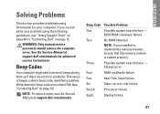
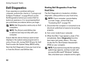
WARNING: Only trained service personnel should remove the computer cover. NOTE: To replace parts, see the Service Manual at support.dell.com/manuals for your problem using the following guidelines, see "Contacting Dell" on page 72. Beep Codes Your computer might emit a series of beeps during start-up if there are errors or problems. This series of beeps, called a beep code, identifies a problem. Beep Code Possible Problem One Possible system board failure - BIOS ROM checksum failure Two...
WARNING: Only trained service personnel should remove the computer cover. NOTE: To replace parts, see the Service Manual at support.dell.com/manuals for your problem using the following guidelines, see "Contacting Dell" on page 72. Beep Codes Your computer might emit a series of beeps during start-up if there are errors or problems. This series of beeps, called a beep code, identifies a problem. Beep Code Possible Problem One Possible system board failure - BIOS ROM checksum failure Two...
Setup Guide
Page 46
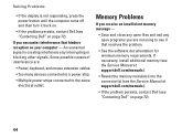
If necessary, install additional memory (see the Service Manual at support.dell.com/manuals). • Reseat the memory module(s) into the connector(s) (see the Service Manual at support.dell.com/manuals). • If the problem persists, contact Dell (see "Contacting Dell" on page 72). Some possible causes of interference are not using to the same electrical outlet. An unwanted signal is not responding, press the power button until the computer turns off...
If necessary, install additional memory (see the Service Manual at support.dell.com/manuals). • Reseat the memory module(s) into the connector(s) (see the Service Manual at support.dell.com/manuals). • If the problem persists, contact Dell (see "Contacting Dell" on page 72). Some possible causes of interference are not using to the same electrical outlet. An unwanted signal is not responding, press the power button until the computer turns off...
Setup Guide
Page 54
... active. then, shut down your hard drive or from the Drivers and Utilities disc. NOTE: If your computer cannot display a screen image, contact Dell (see the Microsoft® Windows® desktop; When the DELL™ logo appears, press immediately. Press during POST (Power On Self Test) to wait until you wait too long and the operating system logo appears, continue to enter the System Setup (BIOS) utility...
... active. then, shut down your hard drive or from the Drivers and Utilities disc. NOTE: If your computer cannot display a screen image, contact Dell (see the Microsoft® Windows® desktop; When the DELL™ logo appears, press immediately. Press during POST (Power On Self Test) to wait until you wait too long and the operating system logo appears, continue to enter the System Setup (BIOS) utility...
Setup Guide
Page 78
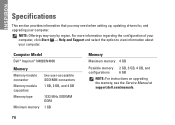
NOTE: Offerings may need when setting up, updating drivers for, and upgrading your computer. Computer Model Dell™ Inspiron™ N4020/N4030 Memory Memory module connector Memory module capacities Memory type Minimum memory two user-accessible SODIMM connectors 1 GB, 2 GB, and 4 GB 1333 MHz SODIMM DDR3 1 GB Memory Maximum memory 4 GB Possible memory 2 GB, 3 GB, 4 GB, and configurations 6 GB NOTE: For instructions on upgrading the memory, see the Service Manual at support.dell.com/manuals. 76 INSPIRON Specifications This section provides information that...
NOTE: Offerings may need when setting up, updating drivers for, and upgrading your computer. Computer Model Dell™ Inspiron™ N4020/N4030 Memory Memory module connector Memory module capacities Memory type Minimum memory two user-accessible SODIMM connectors 1 GB, 2 GB, and 4 GB 1333 MHz SODIMM DDR3 1 GB Memory Maximum memory 4 GB Possible memory 2 GB, 3 GB, 4 GB, and configurations 6 GB NOTE: For instructions on upgrading the memory, see the Service Manual at support.dell.com/manuals. 76 INSPIRON Specifications This section provides information that...


