Specifications
Page 3
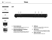
... up to 5 Gbps. 5 Media-card reader Reads from and writes to your computer and charge the battery. 2 Network port (Inspiron 14-5458 and Inspiron 14-5459 only) Connect an Ethernet (RJ45) cable from a router or a broadband modem for network or internet access. 3 HDMI port Connect a TV or another HDMI‑in enabled device. Specifications Front Left Left Views 12 3 4 5 Right Base Display 1 Power-adapter port Connect a power adapter to provide power to media cards. Provides video and audio output. 4 USB 3.0 port Connect peripherals such as storage devices, printers, and so...
... up to 5 Gbps. 5 Media-card reader Reads from and writes to your computer and charge the battery. 2 Network port (Inspiron 14-5458 and Inspiron 14-5459 only) Connect an Ethernet (RJ45) cable from a router or a broadband modem for network or internet access. 3 HDMI port Connect a TV or another HDMI‑in enabled device. Specifications Front Left Left Views 12 3 4 5 Right Base Display 1 Power-adapter port Connect a power adapter to provide power to media cards. Provides video and audio output. 4 USB 3.0 port Connect peripherals such as storage devices, printers, and so...
Specifications
Page 7
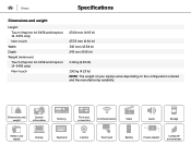
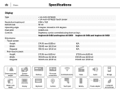
Dimensions and weight System information Memory Ports and connectors Communications Video Audio Storage Media-card reader Display Keyboard Camera Touch pad Battery Power adapter Computer environment Views Specifications Dimensions and weight Height: Touch (Inspiron 14-5458 and Inspiron 14-5459 only) Non-touch Width Depth Weight (minimum): Touch (Inspiron 14-5458 and Inspiron 14-5459 only) Non-touch 23.60 mm (0.93 in) 23.35 mm (0.92 in) 345 mm (13.58 in) 243 mm (9.56 in) 2.18 kg (4.80 lb...
Dimensions and weight System information Memory Ports and connectors Communications Video Audio Storage Media-card reader Display Keyboard Camera Touch pad Battery Power adapter Computer environment Views Specifications Dimensions and weight Height: Touch (Inspiron 14-5458 and Inspiron 14-5459 only) Non-touch Width Depth Weight (minimum): Touch (Inspiron 14-5458 and Inspiron 14-5459 only) Non-touch 23.60 mm (0.93 in) 23.35 mm (0.92 in) 345 mm (13.58 in) 243 mm (9.56 in) 2.18 kg (4.80 lb...
Specifications
Page 8
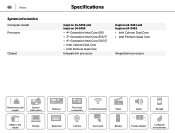
.../i5/i7 • 6th Generation Intel Core i3/i5/i7 • Intel Celeron Dual Core • Intel Pentium Dual Core Integrated in processor Inspiron 14-5451 and Inspiron 14-5452 • Intel Celeron Dual Core • Intel Pentium Quad Core Integrated in processor Dimensions and weight System information Memory Ports and connectors Communications Video Audio Storage Media-card reader Display Keyboard Camera Touch pad Battery Power adapter Computer environment
.../i5/i7 • 6th Generation Intel Core i3/i5/i7 • Intel Celeron Dual Core • Intel Pentium Dual Core Integrated in processor Inspiron 14-5451 and Inspiron 14-5452 • Intel Celeron Dual Core • Intel Pentium Quad Core Integrated in processor Dimensions and weight System information Memory Ports and connectors Communications Video Audio Storage Media-card reader Display Keyboard Camera Touch pad Battery Power adapter Computer environment
Specifications
Page 9
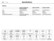
Views Memory Slots Type Speed Configurations supported Specifications Inspiron 14-5458 and Inspiron 14-5459 Two SODIMM slots DDR3L 1600 MHz 2 GB, 4 GB, 6 GB, 8 GB, 12 GB, and 16 GB Inspiron 14-5451 Inspiron 14-5452 One SODIMM slot DDR3L 1300 MHz 2 GB, 4 GB, and 8 GB One SODIMM slot DDR3L 1600 MHz 2 GB, 4 GB, and 8 GB Dimensions and weight System information Memory Ports and connectors Communications Video Audio Storage Media-card reader Display Keyboard Camera Touch pad Battery Power adapter Computer environment
Views Memory Slots Type Speed Configurations supported Specifications Inspiron 14-5458 and Inspiron 14-5459 Two SODIMM slots DDR3L 1600 MHz 2 GB, 4 GB, 6 GB, 8 GB, 12 GB, and 16 GB Inspiron 14-5451 Inspiron 14-5452 One SODIMM slot DDR3L 1300 MHz 2 GB, 4 GB, and 8 GB One SODIMM slot DDR3L 1600 MHz 2 GB, 4 GB, and 8 GB Dimensions and weight System information Memory Ports and connectors Communications Video Audio Storage Media-card reader Display Keyboard Camera Touch pad Battery Power adapter Computer environment
Specifications
Page 10
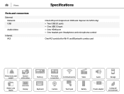
Views Ports and connectors External: Network USB Audio/video Internal: M.2 Specifications One RJ45 port (Inspiron 14-5458 and Inspiron 14-5459 only) • Two USB 2.0 ports • One USB 3.0 port • One HDMI port • One headset port (headphone and microphone combo) One M.2 card slot for Wi-Fi and Bluetooth combo card Dimensions and weight System information Memory Ports and connectors Communications Video Audio Storage Media-card reader Display Keyboard Camera Touch pad Battery Power adapter Computer environment
Views Ports and connectors External: Network USB Audio/video Internal: M.2 Specifications One RJ45 port (Inspiron 14-5458 and Inspiron 14-5459 only) • Two USB 2.0 ports • One USB 3.0 port • One HDMI port • One headset port (headphone and microphone combo) One M.2 card slot for Wi-Fi and Bluetooth combo card Dimensions and weight System information Memory Ports and connectors Communications Video Audio Storage Media-card reader Display Keyboard Camera Touch pad Battery Power adapter Computer environment
Specifications
Page 13
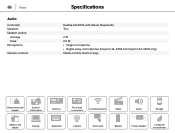
Views Audio Controller Speakers Speaker output: Average Peak Microphone Volume controls Specifications Realtek ALC3234 with Waves MaxxAudio Two 2 W 2.2 W • Single microphone • Digital array-microphones (Inspiron 14-5458 and Inspiron 14-5459 only) Media-control shortcut keys Dimensions and weight System information Memory Ports and connectors Communications Video Audio Storage Media-card reader Display Keyboard Camera Touch pad Battery Power adapter Computer environment
Views Audio Controller Speakers Speaker output: Average Peak Microphone Volume controls Specifications Realtek ALC3234 with Waves MaxxAudio Two 2 W 2.2 W • Single microphone • Digital array-microphones (Inspiron 14-5458 and Inspiron 14-5459 only) Media-control shortcut keys Dimensions and weight System information Memory Ports and connectors Communications Video Audio Storage Media-card reader Display Keyboard Camera Touch pad Battery Power adapter Computer environment
Specifications
Page 14
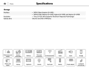
Views Storage Interface Hard drive Optical drive www Specifications • SATA 3 Gbps (Inspiron 14-5451) • SATA 6 Gbps (Inspiron 14-5452, Inspiron 14-5458, and Inspiron 14-5459) • One 2.5-inch drive (supports Intel Smart Response Technology) One 9.5 mm DVD+/-RW drive Dimensions and weight System information Memory Ports and connectors Communications Video Audio Storage Media-card reader Display Keyboard Camera Touch pad Battery Power adapter Computer environment
Views Storage Interface Hard drive Optical drive www Specifications • SATA 3 Gbps (Inspiron 14-5451) • SATA 6 Gbps (Inspiron 14-5452, Inspiron 14-5458, and Inspiron 14-5459) • One 2.5-inch drive (supports Intel Smart Response Technology) One 9.5 mm DVD+/-RW drive Dimensions and weight System information Memory Ports and connectors Communications Video Audio Storage Media-card reader Display Keyboard Camera Touch pad Battery Power adapter Computer environment
Specifications
Page 16
...) 356.31 mm (14.02 in) 173.95 mm (6.85 in) 309.40 mm (12.18 in) 354.95 mm (13.97 in) N/A N/A N/A 173.95 mm (6.85 in) 309.40 mm (12.18 in) 354.95 mm (13.97 in) Dimensions and weight System information Memory Ports and connectors Communications Video Audio Storage Media-card reader Display Keyboard Camera Touch pad Battery Power adapter Computer environment
...) 356.31 mm (14.02 in) 173.95 mm (6.85 in) 309.40 mm (12.18 in) 354.95 mm (13.97 in) N/A N/A N/A 173.95 mm (6.85 in) 309.40 mm (12.18 in) 354.95 mm (13.97 in) Dimensions and weight System information Memory Ports and connectors Communications Video Audio Storage Media-card reader Display Keyboard Camera Touch pad Battery Power adapter Computer environment
Specifications
Page 17
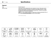
... shortcut keys. NOTE: You can be used to type alternate characters or to perform secondary functions. Dimensions and weight System information Memory Ports and connectors Communications Video Audio Storage Media-card reader Display Keyboard Camera Touch pad Battery Power adapter Computer environment List of the shortcut keys by pressing Fn+Esc or by changing Function Key Behavior in BIOS setup program. To perform secondary functions, press Fn and the desired key. Views Keyboard Type Shortcut keys Specifications Chiclet keyboard Some keys on your keyboard have...
... shortcut keys. NOTE: You can be used to type alternate characters or to perform secondary functions. Dimensions and weight System information Memory Ports and connectors Communications Video Audio Storage Media-card reader Display Keyboard Camera Touch pad Battery Power adapter Computer environment List of the shortcut keys by pressing Fn+Esc or by changing Function Key Behavior in BIOS setup program. To perform secondary functions, press Fn and the desired key. Views Keyboard Type Shortcut keys Specifications Chiclet keyboard Some keys on your keyboard have...
Specifications
Page 18
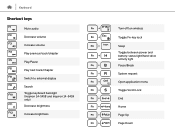
Keyboard Shortcut keys Mute audio Decrease volume Increase volume Play previous track/chapter Play/Pause Play next track/chapter Switch to external display Search Toggle keyboard backlight (Inspiron 14-5458 and Inspiron 14-5459 only) Decrease brightness Increase brightness Turn off/on wireless Toggle Fn-key lock Sleep Toggle between power and battery-status light/hard-drive activity light Pause/Break System request Open application menu Toggle Scroll Lock End Home Page Up Page Down
Keyboard Shortcut keys Mute audio Decrease volume Increase volume Play previous track/chapter Play/Pause Play next track/chapter Switch to external display Search Toggle keyboard backlight (Inspiron 14-5458 and Inspiron 14-5459 only) Decrease brightness Increase brightness Turn off/on wireless Toggle Fn-key lock Sleep Toggle between power and battery-status light/hard-drive activity light Pause/Break System request Open application menu Toggle Scroll Lock End Home Page Up Page Down

Service Manual
Page 11
... your computer. CAUTION: Before touching anything inside the computer, replace all power sources before connecting to servicing that is not authorized by your warranty. CAUTION: When you work surface is not covered by Dell is flat and clean. Some cables have connectors with locking tabs or thumb-screws that the ports and connectors are correctly oriented and aligned. Recommended tools The...
... your computer. CAUTION: Before touching anything inside the computer, replace all power sources before connecting to servicing that is not authorized by your warranty. CAUTION: When you work surface is not covered by Dell is flat and clean. Some cables have connectors with locking tabs or thumb-screws that the ports and connectors are correctly oriented and aligned. Recommended tools The...

Service Manual
Page 13
After working inside your computer CAUTION: Leaving stray or loose screws inside your computer may severely damage your computer. 1 Replace all screws and ensure that no stray screws remain inside your computer. 2 Connect any external devices, peripherals, and cables you removed before working on your computer. 3 Replace any media cards, discs, and any other parts that you removed before working on your computer. 4 Connect your computer and all attached devices to their electrical outlets. 5 Turn on your computer. 13
After working inside your computer CAUTION: Leaving stray or loose screws inside your computer may severely damage your computer. 1 Replace all screws and ensure that no stray screws remain inside your computer. 2 Connect any external devices, peripherals, and cables you removed before working on your computer. 3 Replace any media cards, discs, and any other parts that you removed before working on your computer. 4 Connect your computer and all attached devices to their electrical outlets. 5 Turn on your computer. 13

Service Manual
Page 27
... the instructions in Before working inside your computer. Prerequisites 1 Remove the battery. 2 Remove the base cover. After working inside your computer, follow the steps in After working inside your computer. CAUTION: Removing the coin-cell battery resets the BIOS setup program's settings to default. Procedure Using a plastic scribe, gently pry the coin-cell battery out of the battery socket on the system board. 27 Removing the coin-cell battery WARNING: Before working...
... the instructions in Before working inside your computer. Prerequisites 1 Remove the battery. 2 Remove the base cover. After working inside your computer, follow the steps in After working inside your computer. CAUTION: Removing the coin-cell battery resets the BIOS setup program's settings to default. Procedure Using a plastic scribe, gently pry the coin-cell battery out of the battery socket on the system board. 27 Removing the coin-cell battery WARNING: Before working...

Service Manual
Page 33
... on the hard drive. 3 Replace the screws that secure the hard-drive assembly to the computer base. 7 Connect the hard-drive cable to the hard-drive assembly. 5 Slide the hard-drive assembly in the computer base and align the screw holes on the computer base. 6 Replace the screws that secure the hard drive to the hard-drive bracket. 4 Connect the hard-drive interposer to the system board. Replacing the hard drive WARNING: Before working inside your...
... on the hard drive. 3 Replace the screws that secure the hard-drive assembly to the computer base. 7 Connect the hard-drive cable to the hard-drive assembly. 5 Slide the hard-drive assembly in the computer base and align the screw holes on the computer base. 6 Replace the screws that secure the hard drive to the hard-drive bracket. 4 Connect the hard-drive interposer to the system board. Replacing the hard drive WARNING: Before working inside your...

Service Manual
Page 37
NOTE: If you do not hear the click, remove the memory module and reinstall it clicks into the slot at an angle and gently press the memory module down until it . 1 notch 3 securing clips 5 tab Post-requisites 1 Replace the base cover. 2 Replace the battery. 2 memory module 4 memory-module slot 37 2 Slide the memory module firmly into place.
NOTE: If you do not hear the click, remove the memory module and reinstall it clicks into the slot at an angle and gently press the memory module down until it . 1 notch 3 securing clips 5 tab Post-requisites 1 Replace the base cover. 2 Replace the battery. 2 memory module 4 memory-module slot 37 2 Slide the memory module firmly into place.

Service Manual
Page 56
... working inside your computer. You must enter the Service Tag in After working inside your computer. NOTE: Replacing the system board removes any changes you have made to step 3 in "Removing the hard drive". 6 Remove the wireless card. 7 Remove the keyboard. 8 Remove the computer base. 9 Remove the heat-sink assembly. 10 Remove the I/O board. NOTE: Before disconnecting the cables from step 1 to the BIOS using the BIOS setup program. Procedure 1 Turn the computer over and open the display...
... working inside your computer. You must enter the Service Tag in After working inside your computer. NOTE: Replacing the system board removes any changes you have made to step 3 in "Removing the hard drive". 6 Remove the wireless card. 7 Remove the keyboard. 8 Remove the computer base. 9 Remove the heat-sink assembly. 10 Remove the I/O board. NOTE: Before disconnecting the cables from step 1 to the BIOS using the BIOS setup program. Procedure 1 Turn the computer over and open the display...

Service Manual
Page 63
... the power-adapter port to step 3 in "Removing the hard drive". 6 Remove the wireless card. 7 Remove the keyboard. 8 Remove the computer base. 9 Remove the heat-sink assembly. 10 Remove the I/O board. 11 Remove the system board. Prerequisites 1 Remove the battery. 2 Remove the base cover. 3 Remove the optical drive. 4 Remove the memory modules. 5 Follow the procedure from its routing guides on the palm-rest assembly. 2 Remove the screw that shipped with your computer and follow the instructions in After working inside...
... the power-adapter port to step 3 in "Removing the hard drive". 6 Remove the wireless card. 7 Remove the keyboard. 8 Remove the computer base. 9 Remove the heat-sink assembly. 10 Remove the I/O board. 11 Remove the system board. Prerequisites 1 Remove the battery. 2 Remove the base cover. 3 Remove the optical drive. 4 Remove the memory modules. 5 Follow the procedure from its routing guides on the palm-rest assembly. 2 Remove the screw that shipped with your computer and follow the instructions in After working inside...
Service Manual
Page 66
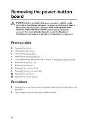
... the instructions in "Removing the hard drive". 6 Remove the wireless card. 7 Remove the keyboard. 8 Remove the computer base. 9 Remove the heat-sink assembly. 10 Remove the I/O board. 11 Remove the system board. For more safety best practices, see the Regulatory Compliance home page at www.dell.com/regulatory_compliance. Prerequisites 1 Remove the battery. 2 Remove the base cover. 3 Remove the optical drive. 4 Remove the memory modules. 5 Follow the procedure from step 1 to access the power-button board. 66 Removing the power-button board WARNING: Before working...
... the instructions in "Removing the hard drive". 6 Remove the wireless card. 7 Remove the keyboard. 8 Remove the computer base. 9 Remove the heat-sink assembly. 10 Remove the I/O board. 11 Remove the system board. For more safety best practices, see the Regulatory Compliance home page at www.dell.com/regulatory_compliance. Prerequisites 1 Remove the battery. 2 Remove the base cover. 3 Remove the optical drive. 4 Remove the memory modules. 5 Follow the procedure from step 1 to access the power-button board. 66 Removing the power-button board WARNING: Before working...
Service Manual
Page 80
... a nontouch screen display. 1 Remove the battery. 2 Remove the base cover. 3 Remove the optical drive. 4 Remove the memory modules. 5 Follow the procedure from step 1 to step 3 in Before working inside your computer. For more safety best practices, see the Regulatory Compliance home page at www.dell.com/regulatory_compliance. After working inside your computer, follow the steps in "Removing the hard drive". 6 Remove the wireless card. 7 Remove the keyboard. 8 Remove the computer base. 9 Remove the heat...
... a nontouch screen display. 1 Remove the battery. 2 Remove the base cover. 3 Remove the optical drive. 4 Remove the memory modules. 5 Follow the procedure from step 1 to step 3 in Before working inside your computer. For more safety best practices, see the Regulatory Compliance home page at www.dell.com/regulatory_compliance. After working inside your computer, follow the steps in "Removing the hard drive". 6 Remove the wireless card. 7 Remove the keyboard. 8 Remove the computer base. 9 Remove the heat...

Service Manual
Page 86
... with a nontouch screen display. 1 Remove the battery. 2 Remove the base cover. 3 Remove the optical drive. 4 Remove the memory modules. 5 Follow the procedure from step 1 to the display backcover. 86 Prerequisites NOTE: These instructions are applicable only for laptops with your computer and follow the instructions in After working inside your computer. For more safety best practices, see the Regulatory Compliance home page at www.dell.com/regulatory_compliance...
... with a nontouch screen display. 1 Remove the battery. 2 Remove the base cover. 3 Remove the optical drive. 4 Remove the memory modules. 5 Follow the procedure from step 1 to the display backcover. 86 Prerequisites NOTE: These instructions are applicable only for laptops with your computer and follow the instructions in After working inside your computer. For more safety best practices, see the Regulatory Compliance home page at www.dell.com/regulatory_compliance...


