

Service Manual
Page 4
... Entering BIOS setup program...59 Navigation keys...59 One time boot menu...59 System setup options...60 System and setup password...69 Assigning a system setup password...70 Deleting or changing an existing system setup password 70 Clearing CMOS settings...70 Clearing BIOS (System Setup) and System passwords 71 Updating the BIOS...71 Updating the BIOS in Windows...71 Updating the BIOS using the USB drive in Windows 71 Updating the BIOS from the F12 One-Time boot menu 72 Chapter 5: Troubleshooting...73 Handling swollen Lithium-ion batteries...73 Locate the Service...
... Entering BIOS setup program...59 Navigation keys...59 One time boot menu...59 System setup options...60 System and setup password...69 Assigning a system setup password...70 Deleting or changing an existing system setup password 70 Clearing CMOS settings...70 Clearing BIOS (System Setup) and System passwords 71 Updating the BIOS...71 Updating the BIOS in Windows...71 Updating the BIOS using the USB drive in Windows 71 Updating the BIOS from the F12 One-Time boot menu 72 Chapter 5: Troubleshooting...73 Handling swollen Lithium-ion batteries...73 Locate the Service...

Service Manual
Page 5
... attached devices from potential damage and to continue. Remove any key to ensure your computer. 5. a. Remove the AC adapter and then press any key to continue the Service Mode procedure. Safety instructions Use the following step if the Owner Tag of your computer. After you finish working inside the computer, replace all open files and exit all covers, panels, and screws before opening the computer cover or panels. NOTE...
... attached devices from potential damage and to continue. Remove any key to ensure your computer. 5. a. Remove the AC adapter and then press any key to continue the Service Mode procedure. Safety instructions Use the following step if the Owner Tag of your computer. After you finish working inside the computer, replace all open files and exit all covers, panels, and screws before opening the computer cover or panels. NOTE...

Service Manual
Page 6
... from the media-card reader. CAUTION: Press and eject any installed card from its pull tab, not the cable itself. If possible, use of catastrophic failure is a memory DIMM that is no longer applicable. The weakened trace may take weeks or months to the damage. Touching the chassis before handling parts does not ensure adequate ESD protection on parts with locking tabs...
... from the media-card reader. CAUTION: Press and eject any installed card from its pull tab, not the cable itself. If possible, use of catastrophic failure is a memory DIMM that is no longer applicable. The weakened trace may take weeks or months to the damage. Touching the chassis before handling parts does not ensure adequate ESD protection on parts with locking tabs...

Service Manual
Page 8
... removed before working on your computer Transporting sensitive components When transporting ESD sensitive components such as replacement parts or parts to be returned to Dell, it is critical to turn on your computer. 4. NOTE: To exit service mode, ensure to connect the AC adapter to normal functioning mode. 8 Working inside your computer. Press the power button to place these parts in anti-static bags for safe transport. After working...
... removed before working on your computer Transporting sensitive components When transporting ESD sensitive components such as replacement parts or parts to be returned to Dell, it is critical to turn on your computer. 4. NOTE: To exit service mode, ensure to connect the AC adapter to normal functioning mode. 8 Working inside your computer. Press the power button to place these parts in anti-static bags for safe transport. After working...
Service Manual
Page 28
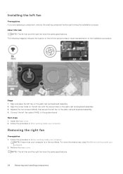
... the system board. Align the screw holes on the left -fan cable (FAN2) to the palm-rest and keyboard assembly. 4. Follow the procedure in Service Mode. Connect the left fan with the screw holes on the palm-rest and keyboard assembly. 2. Removing the right fan Prerequisites 1. Remove the base cover. Align and place the left fan and the right fan have the same specifications. NOTE: The...
... the system board. Align the screw holes on the left -fan cable (FAN2) to the palm-rest and keyboard assembly. 4. Follow the procedure in Service Mode. Connect the left fan with the screw holes on the palm-rest and keyboard assembly. 2. Removing the right fan Prerequisites 1. Remove the base cover. Align and place the left fan and the right fan have the same specifications. NOTE: The...

Service Manual
Page 33
... palm-rest and keyboard assembly. CAUTION: Removing the coin-cell battery resets the BIOS setup program's settings to default. Follow the procedure in Service Mode. Removing and installing components 33 Steps 1. About this task The following image(s) indicate the location of the coin-cell battery and provides a visual representation of the removal procedure. Coin-cell battery Removing the coin-cell battery Prerequisites 1. It is in Before working inside your computer...
... palm-rest and keyboard assembly. CAUTION: Removing the coin-cell battery resets the BIOS setup program's settings to default. Follow the procedure in Service Mode. Removing and installing components 33 Steps 1. About this task The following image(s) indicate the location of the coin-cell battery and provides a visual representation of the removal procedure. Coin-cell battery Removing the coin-cell battery Prerequisites 1. It is in Before working inside your computer...

Service Manual
Page 52
.... You must make the appropriate changes again after you have made to the BIOS using the BIOS setup program. Open the latch and disconnect the keyboard cable from the system board. 12. Remove the screw (M2x3) that secures the antenna cables to the system board. 7. Lift the USB Type-C port-bracket off the system board. 9. Open the latch and disconnect the display cable from the system board. 11. Remove the two screws...
.... You must make the appropriate changes again after you have made to the BIOS using the BIOS setup program. Open the latch and disconnect the keyboard cable from the system board. 12. Remove the screw (M2x3) that secures the antenna cables to the system board. 7. Lift the USB Type-C port-bracket off the system board. 9. Open the latch and disconnect the display cable from the system board. 11. Remove the two screws...

Service Manual
Page 59
..., such as the user password, type of the hard drive. ● Change the system configuration information. ● Set or change the settings in the BIOS Setup program. Navigation keys NOTE: For most of the System Setup options, changes that you write down list, if applicable. Esc Moves to the previous page until you restart the system. NOTE: Depending on . One time boot menu To enter one time boot menu, turn on (or restart...
..., such as the user password, type of the hard drive. ● Change the system configuration information. ● Set or change the settings in the BIOS Setup program. Navigation keys NOTE: For most of the System Setup options, changes that you write down list, if applicable. Esc Moves to the previous page until you restart the system. NOTE: Depending on . One time boot menu To enter one time boot menu, turn on (or restart...

Service Manual
Page 62
... devices such as external hard drive, optical drive, and USB drive. Changes to the date take effect immediately. Changes to their default settings. By default, Enable Camera is selected. USB/Thunderbolt Configuration Enable External USB Ports Enables or disables external USB ports. Enable USB Boot Support Enables or disables booting from a userselected file. ● Delete will delete the selected key. ● Reset All Keys will reset all integrated audio controller. Enable Internal Speaker Enables or disables internal speaker. By default, Enable External USB Ports...
... devices such as external hard drive, optical drive, and USB drive. Changes to the date take effect immediately. Changes to their default settings. By default, Enable Camera is selected. USB/Thunderbolt Configuration Enable External USB Ports Enables or disables external USB ports. Enable USB Boot Support Enables or disables booting from a userselected file. ● Delete will delete the selected key. ● Reset All Keys will reset all integrated audio controller. Enable Internal Speaker Enables or disables internal speaker. By default, Enable External USB Ports...

Service Manual
Page 63
... power of the integrated storage device controller. Default: Auto Mode System setup 63 When enabled, all NVMe and SATA devices will be loaded in order to boot the OS. Windows RST (Intel Rapid Restore Technology) driver, or Linux kernel VMD driver must be mapped under VMD controller. Table 8. Default: 40 Full Screen Logo Enables or disables display of the hard drive. Default: ON Smart Reporting Enable Smart Reporting Enables BIOS to support RAID functions. System setup options-Display menu Display Display Brightness Brightness on battery power Sets the screen brightness...
... power of the integrated storage device controller. Default: Auto Mode System setup 63 When enabled, all NVMe and SATA devices will be loaded in order to boot the OS. Windows RST (Intel Rapid Restore Technology) driver, or Linux kernel VMD driver must be mapped under VMD controller. Table 8. Default: 40 Full Screen Logo Enables or disables display of the hard drive. Default: ON Smart Reporting Enable Smart Reporting Enables BIOS to support RAID functions. System setup options-Display menu Display Display Brightness Brightness on battery power Sets the screen brightness...

Service Manual
Page 66
... System setup System setup options-Passwords menu (continued) Passwords Default: OFF Minimum Characters Sets the minimum characters allowed for SupportAssist OS Recovery tool, in the event of failures equal or greater than the value specified by Dell Auto OS Recovery Threshold, and local Service does not boot, or is not installed. System setup options-Update,Recovery menu Update,Recovery UEFI Capsule Firmware Updates Enable UEFI Capsule Firmware Updates Enables or disables BIOS updates through BIOS recovery file on the primary hard drive or an external USB key...
... System setup System setup options-Passwords menu (continued) Passwords Default: OFF Minimum Characters Sets the minimum characters allowed for SupportAssist OS Recovery tool, in the event of failures equal or greater than the value specified by Dell Auto OS Recovery Threshold, and local Service does not boot, or is not installed. System setup options-Update,Recovery menu Update,Recovery UEFI Capsule Firmware Updates Enable UEFI Capsule Firmware Updates Enables or disables BIOS updates through BIOS recovery file on the primary hard drive or an external USB key...

Service Manual
Page 67
... Recovery tool. System setup options-Update,Recovery menu (continued) Update,Recovery Dell Auto OS Recovery Threshold Controls the automatic boot flow for SupportAssist System Resolution Console and for selection of the computer. Table 13. Default: OFF Auto On Time Enables the computer to briefly power on AC Displays the Service Tag of keyboard backlight timeout value, when an AC adapter is connected. Table 14. Default: ON Fn Lock Options Fn Lock Options Enables or disables the function lock mode. Once set in BIOS...
... Recovery tool. System setup options-Update,Recovery menu (continued) Update,Recovery Dell Auto OS Recovery Threshold Controls the automatic boot flow for SupportAssist System Resolution Console and for selection of the computer. Table 13. Default: OFF Auto On Time Enables the computer to briefly power on AC Displays the Service Tag of keyboard backlight timeout value, when an AC adapter is connected. Table 14. Default: ON Fn Lock Options Fn Lock Options Enables or disables the function lock mode. Once set in BIOS...

Service Manual
Page 70
... System BIOS or System Setup screen, select System Security and press Enter. Assigning a system setup password Prerequisites You can have up message. 5. Use the following guidelines to save the changes and exit from a to delete or change the System and/or Setup password, reenter the new password when prompted. Clearing CMOS settings About this task CAUTION: Clearing CMOS settings will reset the BIOS settings on or reboot. In the System BIOS or System Setup screen, select...
... System BIOS or System Setup screen, select System Security and press Enter. Assigning a system setup password Prerequisites You can have up message. 5. Use the following guidelines to save the changes and exit from a to delete or change the System and/or Setup password, reenter the new password when prompted. Clearing CMOS settings About this task CAUTION: Clearing CMOS settings will reset the BIOS settings on or reboot. In the System BIOS or System Setup screen, select...

Service Manual
Page 71
... -screen instructions. Go to download the latest BIOS setup program file. 2. You can also use the SupportAssist feature to the system board. 7. Follow the procedure from step 1 to step 6 in Updating the BIOS in Windows to www.dell.com/support. 2. Create a bootable USB drive. Connect the bootable USB drive to the bootable USB drive. 4. Remove the coin-cell battery. 4. Replace the base cover. In the Search support box, enter the Service Tag of BIOS, and click Download to download the BIOS...
... -screen instructions. Go to download the latest BIOS setup program file. 2. You can also use the SupportAssist feature to the system board. 7. Follow the procedure from step 1 to step 6 in Updating the BIOS in Windows to www.dell.com/support. 2. Create a bootable USB drive. Connect the bootable USB drive to the bootable USB drive. 4. Remove the coin-cell battery. 4. Replace the base cover. In the Search support box, enter the Service Tag of BIOS, and click Download to download the BIOS...

Service Manual
Page 72
... you downloaded from the Dell Support website and copied to the root of the USB drive ● AC power adapter that is copied to access the One-Time Boot Menu, select BIOS Update using the mouse or arrow keys then press Enter. Updating the BIOS from the F12 One-Time boot menu Update your computer BIOS using the BIOS update.exe file that is connected to the computer ● Functional computer battery to flash the BIOS Perform the following : ● USB drive formatted...
... you downloaded from the Dell Support website and copied to the root of the USB drive ● AC power adapter that is copied to access the One-Time Boot Menu, select BIOS Update using the mouse or arrow keys then press Enter. Updating the BIOS from the F12 One-Time boot menu Update your computer BIOS using the BIOS update.exe file that is connected to the computer ● Functional computer battery to flash the BIOS Perform the following : ● USB drive formatted...

Service Manual
Page 75
... with the video card (GPU) and PC settings. Press and hold both the M key and the power button held down, the battery indicator LED may exhibit two states: a. If there is no failure with the system board b. OFF: No fault detected with the system board, the LCD will flash one of the following error codes for 30 seconds: Table 22. Ensure that indicate if problems were encountered...
... with the video card (GPU) and PC settings. Press and hold both the M key and the power button held down, the battery indicator LED may exhibit two states: a. If there is no failure with the system board b. OFF: No fault detected with the system board, the LCD will flash one of the following error codes for 30 seconds: Table 22. Ensure that indicate if problems were encountered...

Service Manual
Page 76
... internet due to WiFi connectivity issues a WiFi power cycle procedure may occur before your computer boots to enter LCD built-in all Dell computers installed with Windows operating system. Turn on the laptop to the operating system. When you to diagnose hardware issues, repair your computer to isolate the LCD (screen) by running the Built-In Self Test (BIST). Connect only the AC adapter (charger) to conduct a WiFi power cycle: NOTE: Some ISPs (Internet Service...
... internet due to WiFi connectivity issues a WiFi power cycle procedure may occur before your computer boots to enter LCD built-in all Dell computers installed with Windows operating system. Turn on the laptop to the operating system. When you to diagnose hardware issues, repair your computer to isolate the LCD (screen) by running the Built-In Self Test (BIST). Connect only the AC adapter (charger) to conduct a WiFi power cycle: NOTE: Some ISPs (Internet Service...
Setup and Specifications
Page 4
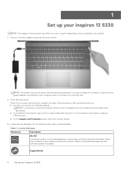
... power adapter and press the power button. Follow the on-screen instructions to conserve charge on for the wireless network access when prompted. ● If connected to the Internet, create an offline account. ● On the Support and Protection screen, enter your Inspiron 13 5330 SupportAssist 4 Set up , Dell recommends that the power adapter is turned on the battery. NOTE: The battery may differ from the Windows Start menu-Recommended. Ensure that you ordered. 1. When setting up your contact details. 3. Locate and use Dell...
... power adapter and press the power button. Follow the on-screen instructions to conserve charge on for the wireless network access when prompted. ● If connected to the Internet, create an offline account. ● On the Support and Protection screen, enter your Inspiron 13 5330 SupportAssist 4 Set up , Dell recommends that the power adapter is turned on the battery. NOTE: The battery may differ from the Windows Start menu-Recommended. Ensure that you ordered. 1. When setting up your contact details. 3. Locate and use Dell...
Setup and Specifications
Page 12
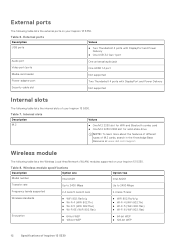
...jack Video port/ports One HDMI 1.4 port Media-card reader Not supported Power-adapter port Two Thunderbolt 4 ports with DisplayPort and Power Delivery Security-cable slot Not supported Internal slots The following table lists the internal slots of your Inspiron 13 5330. External ports The following table lists the external ports on your Inspiron 13 5330. Internal slots Description M.2 Values ● One M.2 2230 slot for WiFi and Bluetooth combo card ● One M.2 2230/2280 slot for solid-state drive NOTE: To learn more about the features of different types of Inspiron 13...
...jack Video port/ports One HDMI 1.4 port Media-card reader Not supported Power-adapter port Two Thunderbolt 4 ports with DisplayPort and Power Delivery Security-cable slot Not supported Internal slots The following table lists the internal slots of your Inspiron 13 5330. External ports The following table lists the external ports on your Inspiron 13 5330. Internal slots Description M.2 Values ● One M.2 2230 slot for WiFi and Bluetooth combo card ● One M.2 2230/2280 slot for solid-state drive NOTE: To learn more about the features of different types of Inspiron 13...
Setup and Specifications
Page 18
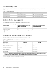
...simulates user environment. † Measured using a 2 ms half-sine pulse. 18 Specifications of your Inspiron 13 5330. Table 18. Operating and storage environment This table lists the operating and storage specifications of Inspiron 13 5330 External display support Graphics card Supported external displays with laptop display enabled Intel UHD Graphics 3 Intel Iris Xe Graphics 3 Supported external displays with laptop display disabled 4 4 NOTE: For more information about external display support, see the External Display Connection Guide on www.dell.com/ support. GPU...
...simulates user environment. † Measured using a 2 ms half-sine pulse. 18 Specifications of your Inspiron 13 5330. Table 18. Operating and storage environment This table lists the operating and storage specifications of Inspiron 13 5330 External display support Graphics card Supported external displays with laptop display enabled Intel UHD Graphics 3 Intel Iris Xe Graphics 3 Supported external displays with laptop display disabled 4 4 NOTE: For more information about external display support, see the External Display Connection Guide on www.dell.com/ support. GPU...


