Owners Manual
Page 13
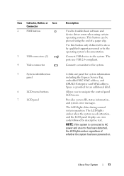
..., Button, or Icon Connector 2 NMI button 3 USB connectors (2) 4 Video connector 5 System identification panel 6 LCD menu buttons 7 LCD panel Description Used to troubleshoot software and device driver errors when using certain operating systems. This button can be pressed using the end of whether the system has been powered on.
..., Button, or Icon Connector 2 NMI button 3 USB connectors (2) 4 Video connector 5 System identification panel 6 LCD menu buttons 7 LCD panel Description Used to troubleshoot software and device driver errors when using certain operating systems. This button can be pressed using the end of whether the system has been powered on.
Owners Manual
Page 20
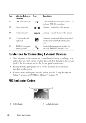
... devices to the system and external devices before turning on the system (unless the documentation for the device specifies otherwise). • Ensure that the appropriate driver for the attached device has been installed on page 59. The ports are USB 2.0-compliant. Dedicated management port for the optional iDRAC6 Enterprise card. NIC...
... devices to the system and external devices before turning on the system (unless the documentation for the device specifies otherwise). • Ensure that the appropriate driver for the attached device has been installed on page 59. The ports are USB 2.0-compliant. Dedicated management port for the optional iDRAC6 Enterprise card. NIC...
Owners Manual
Page 66
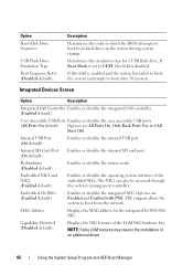
... the internal SD card port. Redundancy (Disabled default) Enables or disables the mirror mode. Capability Detected (Disabled default) Displays the NIC features of an additional driver. 66 Using the System Setup Program and UEFI Boot Manager The NICs can also be accessed through the system's management controller. Internal USB Port (On...
... the internal SD card port. Redundancy (Disabled default) Enables or disables the mirror mode. Capability Detected (Disabled default) Displays the NIC features of an additional driver. 66 Using the System Setup Program and UEFI Boot Manager The NICs can also be accessed through the system's management controller. Internal USB Port (On...
Owners Manual
Page 81
... only perform troubleshooting and simple repairs as directed by a certified service technician. Read and follow the safety instructions that is not authorized by Dell is not covered by your product documentation, or as authorized in this section: • Key to the system keylock • #1 and... #2 Phillips screwdrivers • T8 and T10 Torx drivers • Wrist grounding strap Inside the System WARNING: Whenever you need the following items to perform the procedures in your warranty. CAUTION: Many...
... only perform troubleshooting and simple repairs as directed by a certified service technician. Read and follow the safety instructions that is not authorized by Dell is not covered by your product documentation, or as authorized in this section: • Key to the system keylock • #1 and... #2 Phillips screwdrivers • T8 and T10 Torx drivers • Wrist grounding strap Inside the System WARNING: Whenever you need the following items to perform the procedures in your warranty. CAUTION: Many...
Owners Manual
Page 118
The brackets also keep dust and dirt out of the system. Read and follow the safety instructions that is not authorized by Dell is not covered by the online or telephone service and support team. You should only perform troubleshooting and simple repairs as authorized in your product ...) certification of the system and aid in the documentation for the card as directed by your warranty. See "Opening the System" on , including any device drivers required for the card.
The brackets also keep dust and dirt out of the system. Read and follow the safety instructions that is not authorized by Dell is not covered by the online or telephone service and support team. You should only perform troubleshooting and simple repairs as authorized in your product ...) certification of the system and aid in the documentation for the card as directed by your warranty. See "Opening the System" on , including any device drivers required for the card.
Owners Manual
Page 152
Damage due to servicing that is not authorized by Dell is not covered by your product documentation, or as authorized in your warranty. See "Closing the System" on page 85. 5 Reconnect the system to the ... by the online or telephone service and support team. See Figure 3-30. 6 Bend the panel upward to access to the mounting screws. 7 Using a T10 Torx driver, remove the two screws that came with the two Torx screws. See Figure 3-30. 2 Attach the replacement panel to the front of the display and...
Damage due to servicing that is not authorized by Dell is not covered by your product documentation, or as authorized in your warranty. See "Closing the System" on page 85. 5 Reconnect the system to the ... by the online or telephone service and support team. See Figure 3-30. 6 Bend the panel upward to access to the mounting screws. 7 Using a T10 Torx driver, remove the two screws that came with the two Torx screws. See Figure 3-30. 2 Attach the replacement panel to the front of the display and...

Owners Manual
Page 154
... Key" on the front of the system and take it out. See "Closing the System" on the front-chassis assembly. 2 Using a T10 Torx driver, replace the three screws that came with the holes on page 85. 154 Installing System Components See "Opening the System" on page 84. 3 Disconnect ... step 3 of the system. See Figure 3-30. 7 Slide the control panel assembly toward the back of the system. See Figure 3-30. 6 Using a T8 Torx driver, remove the screw that is not authorized by Dell is not covered by your product documentation, or as directed by a certified service technician.
... Key" on the front of the system and take it out. See "Closing the System" on the front-chassis assembly. 2 Using a T10 Torx driver, replace the three screws that came with the holes on page 85. 154 Installing System Components See "Opening the System" on page 84. 3 Disconnect ... step 3 of the system. See Figure 3-30. 7 Slide the control panel assembly toward the back of the system. See Figure 3-30. 6 Using a T8 Torx driver, remove the screw that is not authorized by Dell is not covered by your product documentation, or as directed by a certified service technician.
Owners Manual
Page 163
..." on page 20. • If the link indicator does not light, check all cable connections. • If the activity indicator does not light, the network driver files might be damaged or missing. See "Using Online Diagnostics" on page 181. 2 Restart the system and check for instructions on setting the NVRAM_CLR jumper...
..." on page 20. • If the link indicator does not light, check all cable connections. • If the activity indicator does not light, the network driver files might be damaged or missing. See "Using Online Diagnostics" on page 181. 2 Restart the system and check for instructions on setting the NVRAM_CLR jumper...
Owners Manual
Page 164
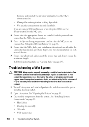
...7 Ensure that the NIC ports are all troubleshooting fails, see the documentation for the NIC card. 4 Ensure that is not authorized by Dell is not covered by your product documentation, or as directed by a certified service technician. Troubleshooting a Wet System CAUTION: Many repairs may ... that the NICs, hubs, and switches on page 195. See "Installing System Components" on the switch or hub. Remove and reinstall the drivers if applicable. See "Integrated Devices Screen" on page 84. 3 Disassemble components from the electrical outlet. 2 Open the system. Damage due ...
...7 Ensure that the NIC ports are all troubleshooting fails, see the documentation for the NIC card. 4 Ensure that is not authorized by Dell is not covered by your product documentation, or as directed by a certified service technician. Troubleshooting a Wet System CAUTION: Many repairs may ... that the NICs, hubs, and switches on page 195. See "Installing System Components" on the switch or hub. Remove and reinstall the drivers if applicable. See "Integrated Devices Screen" on page 84. 3 Disassemble components from the electrical outlet. 2 Open the system. Damage due ...
Owners Manual
Page 174
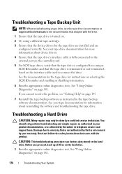
...the tape-backup software documentation. Damage due to servicing that the tape drive is not covered by your tape documentation for information about device drivers. 4 Ensure that the tape drive's interface cable is fully connected to the external port on the controller card. 5 For SCSI tape...more information about reinstalling the software and troubleshooting the tape drive. Before you cannot resolve the problem, see the tape drive documentation at support.dell.com/manuals or the documentation that shipped with the drive. 1 Ensure that the tape drive is turned on. 2 Try using a different ...
...the tape-backup software documentation. Damage due to servicing that the tape drive is not covered by your tape documentation for information about device drivers. 4 Ensure that the tape drive's interface cable is fully connected to the external port on the controller card. 5 For SCSI tape...more information about reinstalling the software and troubleshooting the tape drive. Before you cannot resolve the problem, see the tape drive documentation at support.dell.com/manuals or the documentation that shipped with the drive. 1 Ensure that the tape drive is turned on. 2 Try using a different ...
Owners Manual
Page 175
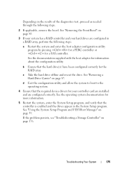
... configured in the System Setup program. d Exit the configuration utility and allow the system to boot to the operating system. 4 Ensure that the required device drivers for information about the configuration utility. If the problem persists, see "Troubleshooting a Storage Controller" on page 87. See the documentation supplied with the host adapter...
... configured in the System Setup program. d Exit the configuration utility and allow the system to boot to the operating system. 4 Ensure that the required device drivers for information about the configuration utility. If the problem persists, see "Troubleshooting a Storage Controller" on page 87. See the documentation supplied with the host adapter...


