Owners Manual
Page 13
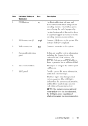
The ports are USB 2.0-compliant. Provides system ID, status information, and system error messages. Connects a monitor to navigate the control panel LCD menu. Allows you to the system. The LCD lights amber when the system needs attention, and the LCD panel displays an error code followed by the operating system's documentation. Use this button only if directed to the system. Space is connected to troubleshoot software and device driver errors when using certain operating systems. This button can be...
The ports are USB 2.0-compliant. Provides system ID, status information, and system error messages. Connects a monitor to navigate the control panel LCD menu. Allows you to the system. The LCD lights amber when the system needs attention, and the LCD panel displays an error code followed by the operating system's documentation. Use this button only if directed to the system. Space is connected to troubleshoot software and device driver errors when using certain operating systems. This button can be...
Owners Manual
Page 27
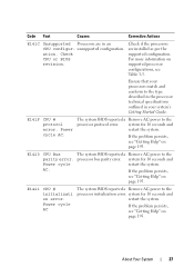
Code Text Causes Corrective Actions E141C Unsupported Processors are installed as per the supported configuration. If the problem persists, see "Getting Help" on page 195. AC. unsupported configuration. Check CPU or BIOS revision. Check if the processors are in your system's Getting Started Guide. E1420 CPU Bus The system BIOS reported a Remove AC power to the processor protocol error. If the problem persists, see "Getting Help" on page 195...
Code Text Causes Corrective Actions E141C Unsupported Processors are installed as per the supported configuration. If the problem persists, see "Getting Help" on page 195. AC. unsupported configuration. Check CPU or BIOS revision. Check if the processors are in your system's Getting Started Guide. E1420 CPU Bus The system BIOS reported a Remove AC power to the processor protocol error. If the problem persists, see "Getting Help" on page 195...

Owners Manual
Page 38
.... If the problem persists, see "Troubleshooting System Memory" on page 130. 38 About Your System The system BIOS disabled memory mirroring because it system for details on the events. I1910 Intrusion System cover removed. The eleventh message instructs the user to check the SEL for more . Check the SEL for 10 seconds and DIMM ##. E2113 Mem mirror OFF on page 169. Review & clear log. Code Text Causes...
.... If the problem persists, see "Troubleshooting System Memory" on page 130. 38 About Your System The system BIOS disabled memory mirroring because it system for details on the events. I1910 Intrusion System cover removed. The eleventh message instructs the user to check the SEL for more . Check the SEL for 10 seconds and DIMM ##. E2113 Mem mirror OFF on page 169. Review & clear log. Code Text Causes...
Owners Manual
Page 51
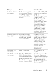
... the expansion card(s). Check the hard-drive configuration settings in System Setup program, or no operating system on page 174. faulty or improperly installed expansion card(s). See "Getting Help" on setting the order of boot devices. Ensure that all appropriate cables are securely connected to the expansion card(s). If the problem persists, see "Troubleshooting Expansion Cards" on page 59. See your hard drive. About Your System 51 Use a bootable USB key, CD, or hard drive. Message Causes...
... the expansion card(s). Check the hard-drive configuration settings in System Setup program, or no operating system on page 174. faulty or improperly installed expansion card(s). See "Getting Help" on setting the order of boot devices. Ensure that all appropriate cables are securely connected to the expansion card(s). If the problem persists, see "Troubleshooting Expansion Cards" on page 59. See your hard drive. About Your System 51 Use a bootable USB key, CD, or hard drive. Message Causes...

Owners Manual
Page 55
... Controller user documentation for any faulty components specified in "Troubleshooting Your System" on performing a field replacement of the flash memory. Unexpected interrupt in the system latest software to information that was logged system reset! reboot. section in the SEL. support.dell.com. or processor combination. See "Troubleshooting System Memory" on page 133. See "Processors" on page 169. Warning: A fatal A fatal system error occurred Check the SEL for instructions...
... Controller user documentation for any faulty components specified in "Troubleshooting Your System" on performing a field replacement of the flash memory. Unexpected interrupt in the system latest software to information that was logged system reset! reboot. section in the SEL. support.dell.com. or processor combination. See "Troubleshooting System Memory" on page 133. See "Processors" on page 169. Warning: A fatal A fatal system error occurred Check the SEL for instructions...
Owners Manual
Page 59
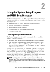
...; Change the NVRAM settings after you add or remove hardware • View the system hardware configuration • Enable or disable integrated devices • Set performance and power management thresholds • Manage system security Choosing the System Boot Mode The System Setup program also enables you to specify the boot mode for more information on page 65 of the "Boot Settings Screen" on this interface. Using the...
...; Change the NVRAM settings after you add or remove hardware • View the system hardware configuration • Enable or disable integrated devices • Set performance and power management thresholds • Manage system security Choosing the System Boot Mode The System Setup program also enables you to specify the boot mode for more information on page 65 of the "Boot Settings Screen" on this interface. Using the...

Owners Manual
Page 65
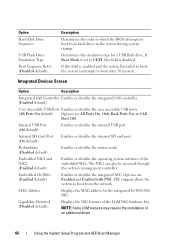
... files needed for startup are located. SATA Settings Screen Option Embedded SATA (Off default) Port A (Off default) Description ATA Mode enables the integrated SATA controller. If the system operating system supports Unified Extensible Firmware Interface, you can switch to a minimum performance state when idle. Displays the family and model number of the processor(s). Using the System Setup Program and UEFI Boot Manager 65 When set this field to SATA port A. Off disables...
... files needed for startup are located. SATA Settings Screen Option Embedded SATA (Off default) Port A (Off default) Description ATA Mode enables the integrated SATA controller. If the system operating system supports Unified Extensible Firmware Interface, you can switch to a minimum performance state when idle. Displays the family and model number of the processor(s). Using the System Setup Program and UEFI Boot Manager 65 When set this field to SATA port A. Off disables...
Owners Manual
Page 66
...'s management controller. Capability Detected (Disabled default) Displays the NIC features of an additional driver. 66 Using the System Setup Program and UEFI Boot Manager Embedded NIC1 and NIC2 (Enabled default) Enables or disables the operating system interface of the embedded NICs. PXE support allows the system to boot from the network. If Boot Mode is set to UEFI, this field is disabled. Internal SD Card Port (On default) Enables or disables the...
...'s management controller. Capability Detected (Disabled default) Displays the NIC features of an additional driver. 66 Using the System Setup Program and UEFI Boot Manager Embedded NIC1 and NIC2 (Enabled default) Enables or disables the operating system interface of the embedded NICs. PXE support allows the system to boot from the network. If Boot Mode is set to UEFI, this field is disabled. Internal SD Card Port (On default) Enables or disables the...
Owners Manual
Page 78
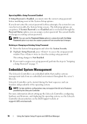
... Lifecycle Controller, configuring hardware and firmware, and deploying the operating system, see the Lifecycle Controller documentation on page 77. Press twice to protect the system password from an embedded environment throughout the server's lifecycle. NOTE: Certain platform configurations may not support the full set of the System Setup options. NOTE: You can use the Password Status option in conjunction with the Setup Password option to clear the existing setup password. The...
... Lifecycle Controller, configuring hardware and firmware, and deploying the operating system, see the Lifecycle Controller documentation on page 77. Press twice to protect the system password from an embedded environment throughout the server's lifecycle. NOTE: Certain platform configurations may not support the full set of the System Setup options. NOTE: You can use the Password Status option in conjunction with the Setup Password option to clear the existing setup password. The...
Owners Manual
Page 118
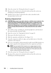
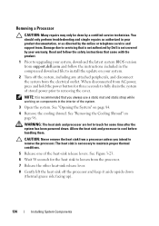
... Install any device drivers required for the card as directed by its electrical outlet and turn the system on page 84. 3 Disconnect all cables from the card. 4 Slide the expansion-card latch out. See Figure 3-16. 5 Grasp the expansion card by the online or telephone service and support team. Read and follow the safety instructions that is not authorized by Dell is not covered by a certified service...
... Install any device drivers required for the card as directed by its electrical outlet and turn the system on page 84. 3 Disconnect all cables from the card. 4 Slide the expansion-card latch out. See Figure 3-16. 5 Grasp the expansion card by the online or telephone service and support team. Read and follow the safety instructions that is not authorized by Dell is not covered by a certified service...
Owners Manual
Page 134
... by the online or telephone service and support team. You should only perform troubleshooting and simple repairs as authorized in the interior of the system. 3 Open the system. Damage due to servicing that you intend to install the update on components in your warranty. When disconnected from a processor unless you always use a static mat and static strap while working on your system. 2 Turn off...
... by the online or telephone service and support team. You should only perform troubleshooting and simple repairs as authorized in the interior of the system. 3 Open the system. Damage due to servicing that you intend to install the update on components in your warranty. When disconnected from a processor unless you always use a static mat and static strap while working on your system. 2 Turn off...

Owners Manual
Page 154
... by Dell is not covered by the online or telephone service and support team. See "Opening the System" on page 112. 5 Using a T10 Torx driver, remove the three screws that secures the control panel board on page 98. 7 Close the system. See "Internal USB Memory Key" on page 84. 3 Disconnect the cables connected to the front-chassis assembly. See Figure 3-30. 3 Using a T8 Torx driver, replace the screw that secure the control panel...
... by Dell is not covered by the online or telephone service and support team. See "Opening the System" on page 112. 5 Using a T10 Torx driver, remove the three screws that secures the control panel board on page 98. 7 Close the system. See "Internal USB Memory Key" on page 84. 3 Disconnect the cables connected to the front-chassis assembly. See Figure 3-30. 3 Using a T8 Torx driver, replace the screw that secure the control panel...
Owners Manual
Page 163
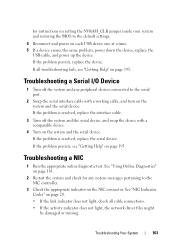
... problem, power down the device, replace the USB cable, and power up the device. Troubleshooting Your System 163 See "NIC Indicator Codes" on page 20. • If the link indicator does not light, check all troubleshooting fails, see "Getting Help" on the system and the serial device. for any peripheral devices connected to the serial port. 2 Swap the serial interface cable with a comparable device. 4 Turn on the system and the serial...
... problem, power down the device, replace the USB cable, and power up the device. Troubleshooting Your System 163 See "NIC Indicator Codes" on page 20. • If the link indicator does not light, check all troubleshooting fails, see "Getting Help" on the system and the serial device. for any peripheral devices connected to the serial port. 2 Swap the serial interface cable with a comparable device. 4 Turn on the system and the serial...
Owners Manual
Page 164
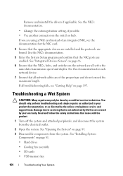
... NIC ports are using a NIC card instead of the proper type and do not exceed the maximum length. See the NIC's documentation. 5 Enter the System Setup program and confirm that the appropriate drivers are installed and the protocols are of an integrated NIC, see "Getting Help" on page 81. • Hard drives • Cooling fan assembly • SD cards • USB memory key 164 Troubleshooting Your...
... NIC ports are using a NIC card instead of the proper type and do not exceed the maximum length. See the NIC's documentation. 5 Enter the System Setup program and confirm that the appropriate drivers are installed and the protocols are of an integrated NIC, see "Getting Help" on page 81. • Hard drives • Cooling fan assembly • SD cards • USB memory key 164 Troubleshooting Your...
Owners Manual
Page 165
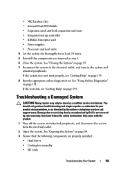
... repairs as directed by the online or telephone service and support team. Read and follow the safety instructions that the following components are properly installed: • Hard drives • Cooling fan assembly • SD cards Troubleshooting Your System 165 See "Opening the System" on page 195. 8 Run the appropriate online diagnostic test. If the tests fail, see "Getting Help" on page 84. 3 Ensure that came with the product. 1 Turn...
... repairs as directed by the online or telephone service and support team. Read and follow the safety instructions that the following components are properly installed: • Hard drives • Cooling fan assembly • SD cards Troubleshooting Your System 165 See "Opening the System" on page 195. 8 Run the appropriate online diagnostic test. If the tests fail, see "Getting Help" on page 84. 3 Ensure that came with the product. 1 Turn...
Owners Manual
Page 167
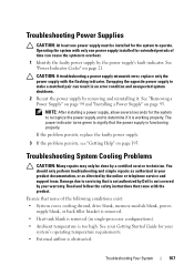
... it is working properly. See "Removing a Power Supply" on page 94 and "Installing a Power Supply" on page 195. See "Power Indicator Codes" on page 21. Ensure that is not authorized by Dell is not covered by a certified service technician. CAUTION: If troubleshooting a power supply mismatch error, replace only the power supply with the product. See your Getting Started Guide for your product documentation, or as authorized in single-processor configurations). •...
... it is working properly. See "Removing a Power Supply" on page 94 and "Installing a Power Supply" on page 195. See "Power Indicator Codes" on page 21. Ensure that is not authorized by Dell is not covered by a certified service technician. CAUTION: If troubleshooting a power supply mismatch error, replace only the power supply with the product. See your Getting Started Guide for your product documentation, or as authorized in single-processor configurations). •...
Owners Manual
Page 172
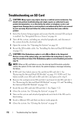
... set to Disabled, proceed to step 8. 6 Remove the card present in your warranty. See "Opening the System" on page 85. 172 Troubleshooting Your System See "Closing the System" on page 84. 4 Reseat the SD module cable. Read and follow the instructions in step 5 to step 9 to servicing that you know works properly. 11 Close the system. See "Closing the System" on page 85. 9 Turn...
... set to Disabled, proceed to step 8. 6 Remove the card present in your warranty. See "Opening the System" on page 85. 172 Troubleshooting Your System See "Closing the System" on page 84. 4 Reseat the SD module cable. Read and follow the instructions in step 5 to step 9 to servicing that you know works properly. 11 Close the system. See "Closing the System" on page 85. 9 Turn...
Owners Manual
Page 173
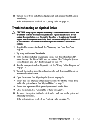
... Setup program and ensure that is not authorized by Dell is not covered by your product documentation, or as directed by a certified service technician. Damage due to the electrical outlet, and turn on page 59. 4 Run the appropriate online diagnostic test. Troubleshooting an Optical Drive CAUTION: Many repairs may only be done by the online or telephone service and support team. Read and follow the safety instructions...
... Setup program and ensure that is not authorized by Dell is not covered by your product documentation, or as directed by a certified service technician. Damage due to the electrical outlet, and turn on page 59. 4 Run the appropriate online diagnostic test. Troubleshooting an Optical Drive CAUTION: Many repairs may only be done by the online or telephone service and support team. Read and follow the safety instructions...
Owners Manual
Page 174
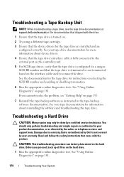
... connected to the external port on selecting the SCSI ID number and enabling or disabling termination. 6 Run the appropriate online diagnostics tests. Before you cannot resolve the problem, see the tape drive documentation at support.dell.com/manuals or the documentation that shipped with the product. See "Using Online Diagnostics" on the interface cable used to servicing that is not authorized by a certified service technician. See your warranty. Troubleshooting a Hard Drive CAUTION: Many repairs...
... connected to the external port on selecting the SCSI ID number and enabling or disabling termination. 6 Run the appropriate online diagnostics tests. Before you cannot resolve the problem, see the tape drive documentation at support.dell.com/manuals or the documentation that shipped with the product. See "Using Online Diagnostics" on the interface cable used to servicing that is not authorized by a certified service technician. See your warranty. Troubleshooting a Hard Drive CAUTION: Many repairs...
Owners Manual
Page 177
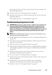
... online or telephone service and support team. You should only perform troubleshooting and simple repairs as authorized in its electrical outlet, and turn off the system and attached peripherals, and disconnect the system from the electrical outlet. 9 Open the system. If the problem persists, see the documentation for your warranty. See "Opening the System" on page 116. 6 Close the system. Troubleshooting Expansion Cards...
... online or telephone service and support team. You should only perform troubleshooting and simple repairs as authorized in its electrical outlet, and turn off the system and attached peripherals, and disconnect the system from the electrical outlet. 9 Open the system. If the problem persists, see the documentation for your warranty. See "Opening the System" on page 116. 6 Close the system. Troubleshooting Expansion Cards...


