User's Guide (HTML)
Page 18
The cartridge clicks into the new imaging drum kit by aligning the white rollers on the toner cartridge with the toner cartridge assembly into the printer by printing the printer settings configuration sheet. When the Toner low message appears, or when you should reset the imaging drum's counter... blue arrows found in your warranty. 10. Replacing the Toner Cartridge You can determine approximately how much toner is left in the printer and pushing the imaging drum into place when correctly installed. 9. Repeat this procedure multiple times until print remains faded. When the print...
The cartridge clicks into the new imaging drum kit by aligning the white rollers on the toner cartridge with the toner cartridge assembly into the printer by printing the printer settings configuration sheet. When the Toner low message appears, or when you should reset the imaging drum's counter... blue arrows found in your warranty. 10. Replacing the Toner Cartridge You can determine approximately how much toner is left in the printer and pushing the imaging drum into place when correctly installed. 9. Repeat this procedure multiple times until print remains faded. When the print...

User's Guide (HTML)
Page 19
...cause print quality problems. 1. Install the new toner cartridge assembly by pressing the button on the right side of the printer and lowering the cover. 3. Turn the printer off. 2. NOTICE: When replacing a toner cartridge assembly, do not leave the new cartridge exposed to direct light for... an extended period of time. Unpack the new toner cartridge assembly. Open the front cover by aligning the white rollers on the toner cartridge ...
...cause print quality problems. 1. Install the new toner cartridge assembly by pressing the button on the right side of the printer and lowering the cover. 3. Turn the printer off. 2. NOTICE: When replacing a toner cartridge assembly, do not leave the new cartridge exposed to direct light for... an extended period of time. Unpack the new toner cartridge assembly. Open the front cover by aligning the white rollers on the toner cartridge ...
User's Guide (HTML)
Page 61
CAUTION: The inside of the printer might be hot. Install the toner cartridge assembly into place when correctly installed. The cartridge clicks into the imaging drum kit by aligning the white rollers on the toner cartridge with the white arrows on the base of the imaging drum kit and ...Press the button on the tracks of injury from a hot component, allow the surface to cool before touching it out of the printer might be hot. CAUTION: The inside of the printer. To reduce the risk of injury from a hot component, allow the surface to cool before touching it will go.
CAUTION: The inside of the printer might be hot. Install the toner cartridge assembly into place when correctly installed. The cartridge clicks into the imaging drum kit by aligning the white rollers on the toner cartridge with the white arrows on the base of the imaging drum kit and ...Press the button on the tracks of injury from a hot component, allow the surface to cool before touching it out of the printer might be hot. CAUTION: The inside of the printer. To reduce the risk of injury from a hot component, allow the surface to cool before touching it will go.

User's Guide (HTML)
Page 63
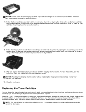
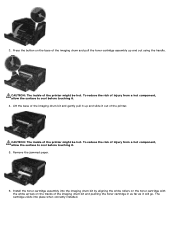
... be hot. The cartridge clicks into place when correctly installed. Install the imaging drum kit with the toner cartridge assembly into the printer by aligning the white rollers on the tracks of the imaging drum kit and gently pull it up and slide it . 4. To reduce the risk of injury from a ...hot component, allow the surface to cool before touching it. 5. Install the toner cartridge assembly into the printer as far as it will go . ...
... be hot. The cartridge clicks into place when correctly installed. Install the imaging drum kit with the toner cartridge assembly into the printer by aligning the white rollers on the tracks of the imaging drum kit and gently pull it up and slide it . 4. To reduce the risk of injury from a ...hot component, allow the surface to cool before touching it. 5. Install the toner cartridge assembly into the printer as far as it will go . ...

User's Guide (HTML)
Page 72
... far into place when correctly installed. 5. Paper jam in as far as it . Pull the paper firmly to cool before checking the printer. NOTE: Turn the printer off before touching. Press the button on the toner cartridge assembly, and then pull the toner cartridge up and out using the handle. ...3. Pull the paper out. 4. The cartridge clicks into the printer, open the front cover of the printer by aligning the white rollers on the toner cartridge with the white arrows on the right side of the imaging drum and pushing the toner...
... far into place when correctly installed. 5. Paper jam in as far as it . Pull the paper firmly to cool before checking the printer. NOTE: Turn the printer off before touching. Press the button on the toner cartridge assembly, and then pull the toner cartridge up and out using the handle. ...3. Pull the paper out. 4. The cartridge clicks into the printer, open the front cover of the printer by aligning the white rollers on the toner cartridge with the white arrows on the right side of the imaging drum and pushing the toner...

Service Manual
Page 4
... Hardware tests 3-8 Duplex tests 3-9 Input tray tests 3-10 Output bin tests 3-11 Base sensor test (B. sensor test 3-11 Printer setup 3-12 EP setup 3-13 Event log 3-14 Exit Diagnostics 3-15 Printhead assembly electronic adjustment 3-16 Printhead assembly mechanical adjustment 3-...17 Repair information 4-1 Handling ESD-sensitive parts 4-1 Removal procedures 4-2 ACM pick tire roller removal 4-3 Bezel removal 4-5 Controller board removal 4-6 Cover open sensor 4-8 Door mount removal 4-9 Duplex removal 4-11 Duplex/main...
... Hardware tests 3-8 Duplex tests 3-9 Input tray tests 3-10 Output bin tests 3-11 Base sensor test (B. sensor test 3-11 Printer setup 3-12 EP setup 3-13 Event log 3-14 Exit Diagnostics 3-15 Printhead assembly electronic adjustment 3-16 Printhead assembly mechanical adjustment 3-...17 Repair information 4-1 Handling ESD-sensitive parts 4-1 Removal procedures 4-2 ACM pick tire roller removal 4-3 Bezel removal 4-5 Controller board removal 4-6 Cover open sensor 4-8 Door mount removal 4-9 Duplex removal 4-11 Duplex/main...
Service Manual
Page 36
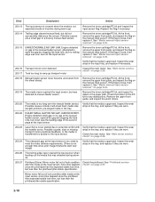
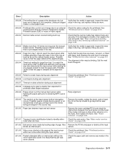
... the gap by stopping the feed rolls, but never saw the leading edge of lock condition after the media at the input sensor. 200.23 Laser Servo never started due to the input sensor. At the front, remove the upper front guide, and inspect the flag on the manual input sensor... The media never reached the input sensor, but less than the printhead jitter-stable specification. 2-10 Remove the upper front guide, and inspect the pinch rollers. 200.20 The media is loose, then replace it. Verify that the media is approved. Inspect the wear strips in machine during warmup. 200.27...
... the gap by stopping the feed rolls, but never saw the leading edge of lock condition after the media at the input sensor. 200.23 Laser Servo never started due to the input sensor. At the front, remove the upper front guide, and inspect the flag on the manual input sensor... The media never reached the input sensor, but less than the printhead jitter-stable specification. 2-10 Remove the upper front guide, and inspect the pinch rollers. 200.20 The media is loose, then replace it. Verify that the media is approved. Inspect the wear strips in machine during warmup. 200.27...
Service Manual
Page 37
Inspect the wear laser servo cleanup is designed to handle. See event beyond the wear strips. 201.00 Paper ...freely and securely. See "Rear exit guide assembly with paper dust. Replace the pick tires if necessary. See "ACM pick tire roller removal" on page 2-26. 201.02 Exit sensor never made by leading edge of page. See "Main motor service check" on...in the tray. Possible cause is that the page is delayed at least as far as internal jam. The alignment roller may be binding. It is likely that the jam was later detected at the manual feed sensor while flushing the ...
Inspect the wear laser servo cleanup is designed to handle. See event beyond the wear strips. 201.00 Paper ...freely and securely. See "Rear exit guide assembly with paper dust. Replace the pick tires if necessary. See "ACM pick tire roller removal" on page 2-26. 201.02 Exit sensor never made by leading edge of page. See "Main motor service check" on...in the tray. Possible cause is that the page is delayed at least as far as internal jam. The alignment roller may be binding. It is likely that the jam was later detected at the manual feed sensor while flushing the ...
Service Manual
Page 38
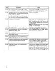
... output bin, open to stop at the fuser, rear door, exit guide, and top cover. If damage is located behind the fuser exit rollers, about mid printer. Open the rear door, and inspect the flag on the exit sensor. Open the rear door, and inspect the flag on the exit sensor...4-20. 202.32 Long media or shingled multi feed stopped before fuser reached acceptable operating temperature. If there is located behind the fuser exit rollers, about mid printer. See "Rear exit guide assembly with the rear door open the reat door and obscure the trailing edge and the sensor flag. See "...
... output bin, open to stop at the fuser, rear door, exit guide, and top cover. If damage is located behind the fuser exit rollers, about mid printer. Open the rear door, and inspect the flag on the exit sensor. Open the rear door, and inspect the flag on the exit sensor...4-20. 202.32 Long media or shingled multi feed stopped before fuser reached acceptable operating temperature. If there is located behind the fuser exit rollers, about mid printer. See "Rear exit guide assembly with the rear door open the reat door and obscure the trailing edge and the sensor flag. See "...

Service Manual
Page 39
... Duplex jam while picking from tray 1. If the flag does not rotate freely, then replace the paper input and duplex sensor. Replace the pick rollers if they are no obstructions and the problem persists, then disconnect all of the duplex sensor. Remove the tray and inspect the media path for... Duplex sensor never made . See "Paper input and duplex sensor assembly removal" on a wireless unit), and inspect the flag of the cables, tilt the printer onto its back (be sure to the output bin. Also check the wear strips, and replace if necessary. 241.12 Second pick from the duplex...
... Duplex jam while picking from tray 1. If the flag does not rotate freely, then replace the paper input and duplex sensor. Replace the pick rollers if they are no obstructions and the problem persists, then disconnect all of the duplex sensor. Remove the tray and inspect the media path for... Duplex sensor never made . See "Paper input and duplex sensor assembly removal" on a wireless unit), and inspect the flag of the cables, tilt the printer onto its back (be sure to the output bin. Also check the wear strips, and replace if necessary. 241.12 Second pick from the duplex...
Service Manual
Page 40
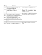
... feed from tray 2. Check the pick tires for obstruction in the paper path have been flushed to the output bin. Inspect the pick roller on the MPF or the rollers on the manual feed. Error Description Action 242.12 Second pick from manual feeder, tray 1, or feeder failed when media was in... the MPF has been pushed in too far. 251.21 The media in the MPF has been pushed in too far. If the MPF pick roller is damaged or worn, then replace the MPF. Remove Tray 2 and inspect for wear or paper dust. For...
... feed from tray 2. Check the pick tires for obstruction in the paper path have been flushed to the output bin. Inspect the pick roller on the MPF or the rollers on the manual feed. Error Description Action 242.12 Second pick from manual feeder, tray 1, or feeder failed when media was in... the MPF has been pushed in too far. 251.21 The media in the MPF has been pushed in too far. If the MPF pick roller is damaged or worn, then replace the MPF. Remove Tray 2 and inspect for wear or paper dust. For...

Service Manual
Page 59
...spilled toner. A transfer roll contaminated with toner can cause toner to transfer to contaminate the transfer roller. Verify the high voltage cable is plugged into the LVPS/HVPS. Replace the fuser as necessary.... as light or dark horizontal lines on a uniformly gray page or on toner. With the printer off, check to a variation in the speed of the proper high voltages can be a result... card Action Make sure the toner cartridge and PC Kit are installed correctly and that the laser beam is not blocked. It may also be checked. Inspect the transfer roll for contamination ...
...spilled toner. A transfer roll contaminated with toner can cause toner to transfer to contaminate the transfer roller. Verify the high voltage cable is plugged into the LVPS/HVPS. Replace the fuser as necessary.... as light or dark horizontal lines on a uniformly gray page or on toner. With the printer off, check to a variation in the speed of the proper high voltages can be a result... card Action Make sure the toner cartridge and PC Kit are installed correctly and that the laser beam is not blocked. It may also be checked. Inspect the transfer roll for contamination ...
Service Manual
Page 85
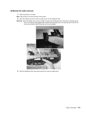
Place the printer on its side. After the ACM pick tires have been pulled out, close the duplex door. Repair information 4-3 Warning: Open the duplex door only far enough to pull out the ACM pick tires. Open the duplex jam door just far enough to remove the ACM pick tires. The tray may go in but will not come out, and will render the printer as non-serviceable. 3. If the door is opened too far, then it can become disengaged and interfere with the paper tray. ACM pick tire roller removal 1. Note: Be careful to not mar the finish of the printer. 2.
Place the printer on its side. After the ACM pick tires have been pulled out, close the duplex door. Repair information 4-3 Warning: Open the duplex door only far enough to pull out the ACM pick tires. Open the duplex jam door just far enough to remove the ACM pick tires. The tray may go in but will not come out, and will render the printer as non-serviceable. 3. If the door is opened too far, then it can become disengaged and interfere with the paper tray. ACM pick tire roller removal 1. Note: Be careful to not mar the finish of the printer. 2.

Service Manual
Page 86
Remove the ACM pick tire roller (A). Note: • If the left hub is gray, then disconnect the old right and left tire/hub assemblies from the ACM, and replace with the new right and left tire/hub assemblies. • If the left hub is black, then remove the old right and left tires from the ACM hubs, and replace with the new tires. A 4-4 Do not attempt to remove the hubs. 4.
Remove the ACM pick tire roller (A). Note: • If the left hub is gray, then disconnect the old right and left tire/hub assemblies from the ACM, and replace with the new right and left tire/hub assemblies. • If the left hub is black, then remove the old right and left tires from the ACM hubs, and replace with the new tires. A 4-4 Do not attempt to remove the hubs. 4.

Service Manual
Page 170
... P651D N382M N383M M663M M664M P329M FAN, COOLING, 2WIRE, 24V, PRINTER/PRINTER ACCESSORIES, 2330 FRU ROLLER, TRANSFER, PRINTER/PRINTER ACCESSORIES, 2330 FRU ROLLER, PK-ARM, 2TIRES, PRINTER/PRINTER ACCESSORIES, 2330 CRU SENSOR, CARTRIDGE, TONER, CBL-NO, 2330 FRU SNSR,CVR-ACCESS,ASSY,PTR,2330 FRU ROLLER, PK-ARM, 550-TRAY, PRINTER/PRINTER ACCESSORIES, 2330 CRU (with Instruction sheet) TRAY, PAPER, ASSEMBLY...
... P651D N382M N383M M663M M664M P329M FAN, COOLING, 2WIRE, 24V, PRINTER/PRINTER ACCESSORIES, 2330 FRU ROLLER, TRANSFER, PRINTER/PRINTER ACCESSORIES, 2330 FRU ROLLER, PK-ARM, 2TIRES, PRINTER/PRINTER ACCESSORIES, 2330 CRU SENSOR, CARTRIDGE, TONER, CBL-NO, 2330 FRU SNSR,CVR-ACCESS,ASSY,PTR,2330 FRU ROLLER, PK-ARM, 550-TRAY, PRINTER/PRINTER ACCESSORIES, 2330 CRU (with Instruction sheet) TRAY, PAPER, ASSEMBLY...


