User's Guide (HTML)
Page 60
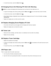
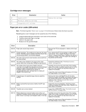
... the Toner Alarm set to redistribute the toner within the cartridge. To cancel the print job, press the Cancel button . Print a Printer Settings configuration sheet to determine the imaging drum level. Replace the imaging drum, and then reset the counter. 84 Replace Imaging Drum/Replace... Menu Settings Page. To cancel the print job, press the Cancel button . 200 Paper Jam There is a paper jam at the printer input sensor. 1. The current job may not print correctly. Replace the toner cartridge. 88 Replace Toner Cartridge Replace the specified toner cartridge. The remainder ...
... the Toner Alarm set to redistribute the toner within the cartridge. To cancel the print job, press the Cancel button . Print a Printer Settings configuration sheet to determine the imaging drum level. Replace the imaging drum, and then reset the counter. 84 Replace Imaging Drum/Replace... Menu Settings Page. To cancel the print job, press the Cancel button . 200 Paper Jam There is a paper jam at the printer input sensor. 1. The current job may not print correctly. Replace the toner cartridge. 88 Replace Toner Cartridge Replace the specified toner cartridge. The remainder ...
User's Guide (HTML)
Page 62
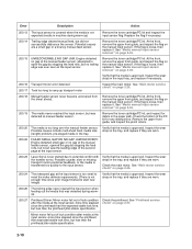
.... 201 Paper Jam There is a paper jam between the printer input and paper exit sensors. 1. Install the imaging drum kit with the toner cartridge assembly into the printer by pressing the button on the right side of the printer and lowering the cover. 3. Turn the printer back on the base of the imaging drum kit with...
.... 201 Paper Jam There is a paper jam between the printer input and paper exit sensors. 1. Install the imaging drum kit with the toner cartridge assembly into the printer by pressing the button on the right side of the printer and lowering the cover. 3. Turn the printer back on the base of the imaging drum kit with...
Service Manual
Page 4
sensor test 3-11 Printer setup 3-12 EP setup 3-13 Event log 3-14 Exit Diagnostics 3-15 Printhead assembly electronic adjustment 3-16 Printhead assembly mechanical adjustment 3-17 Repair information 4-1 Handling ESD-sensitive parts 4-1 Removal procedures 4-2 ACM pick tire roller removal 4-3 Bezel removal 4-5 Controller board removal 4-6 Cover open sensor...removal 4-34 Media ACM ASM feeder removal 4-37 Media feed clutch with cable removal 4-40 Media manual input sensor 4-42 Multipurpose feeder (MPF) removal 4-45 Multipurpose feeder (MPF) feed clutch removal 4-48 Nameplate ...
sensor test 3-11 Printer setup 3-12 EP setup 3-13 Event log 3-14 Exit Diagnostics 3-15 Printhead assembly electronic adjustment 3-16 Printhead assembly mechanical adjustment 3-17 Repair information 4-1 Handling ESD-sensitive parts 4-1 Removal procedures 4-2 ACM pick tire roller removal 4-3 Bezel removal 4-5 Controller board removal 4-6 Cover open sensor...removal 4-34 Media ACM ASM feeder removal 4-37 Media feed clutch with cable removal 4-40 Media manual input sensor 4-42 Multipurpose feeder (MPF) removal 4-45 Multipurpose feeder (MPF) feed clutch removal 4-48 Nameplate ...

Service Manual
Page 5
Operator panel removal 4-51 Paper input and duplex sensor assembly removal 4-52 Printhead removal 4-53 Rear door and rear cover removal 4-54 Rear exit guide assembly with sensor and reversing solenoid removal 4-56 Right side cover assembly removal 4-58 Toner level sensor removal 4-60 Top cover assembly removal 4-61 Transfer roll removal 4-63 Upper front...
Operator panel removal 4-51 Paper input and duplex sensor assembly removal 4-52 Printhead removal 4-53 Rear door and rear cover removal 4-54 Rear exit guide assembly with sensor and reversing solenoid removal 4-56 Right side cover assembly removal 4-58 Toner level sensor removal 4-60 Top cover assembly removal 4-61 Transfer roll removal 4-63 Upper front...

Service Manual
Page 23
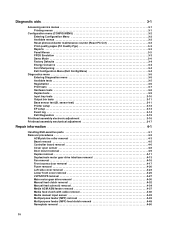
Tips on preventing jams Paper path I J F G E H K L C B D M A A Paper path B Manual feed sensor C Upper end feed rolls D Input sensor E Transfer roll F Fuser G Fuser exit rolls H Fuser exit sensor I Exit rolls J Exit sensor K Duplex unit L Duplex sensor M Auto compensator A-B 125.3 mm B-C 9.0 mm C-D 59.8 mm D-E 44.9 mm E-F 112.7 mm F-G 21.4 mm G-H 114.8 mm H-I 7.5 mm I-J 17.0 mm I-K 211.7 mm K-L 93.4 mm L-M 8.4 mm General information 1-7
Tips on preventing jams Paper path I J F G E H K L C B D M A A Paper path B Manual feed sensor C Upper end feed rolls D Input sensor E Transfer roll F Fuser G Fuser exit rolls H Fuser exit sensor I Exit rolls J Exit sensor K Duplex unit L Duplex sensor M Auto compensator A-B 125.3 mm B-C 9.0 mm C-D 59.8 mm D-E 44.9 mm E-F 112.7 mm F-G 21.4 mm G-H 114.8 mm H-I 7.5 mm I-J 17.0 mm I-K 211.7 mm K-L 93.4 mm L-M 8.4 mm General information 1-7
Service Manual
Page 35
...not expected page (bouncy passthru sensor) Remove the toner cartridge/PC kit. See "Media manual input sensor removal" on page 4-39. 200.08 Media reached the input sensor before interrupt occurred-not enough time elapsed since the printhead started to media prestaged in the printer and the driver. 200....03 The video never started Inspect the LVPS/HVPS. It should rotate freely. Possible causes include bouncy sensor or exceptionally fast pick- Inspect the input sensor flag and replace it if it does not...
...not expected page (bouncy passthru sensor) Remove the toner cartridge/PC kit. See "Media manual input sensor removal" on page 4-39. 200.08 Media reached the input sensor before interrupt occurred-not enough time elapsed since the printhead started to media prestaged in the printer and the driver. 200....03 The video never started Inspect the LVPS/HVPS. It should rotate freely. Possible causes include bouncy sensor or exceptionally fast pick- Inspect the input sensor flag and replace it if it does not...
Service Manual
Page 36
... measured gap at manual feeder sensor. See "Media manual input sensor removal" on page 4-39. 200.19 The media never reached the input sensor, but did not successfully debounce the sensor. Mirror motor fell out of lock condition after media at the input sensor. 200.23 Laser Servo never started due to open... the gap by stopping the feed rolls, but never saw the leading edge of the PC kit for debris in the tray. See "Media manual input sensor removal" on page 4-39. ...
... measured gap at manual feeder sensor. See "Media manual input sensor removal" on page 4-39. 200.19 The media never reached the input sensor, but did not successfully debounce the sensor. Mirror motor fell out of lock condition after media at the input sensor. 200.23 Laser Servo never started due to open... the gap by stopping the feed rolls, but never saw the leading edge of the PC kit for debris in the tray. See "Media manual input sensor removal" on page 4-39. ...
Service Manual
Page 37
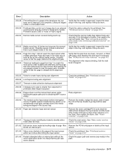
...as internal jam. media or a fast paper feed. 200.29 Printhead drive control out of a page at the input sensor within two inches after hitting the input sensor Check the printhead. "Printhead service check" on page 4-3. Possible causes include multi-sheet feed or pre-staged media...media flag rotates freely and securely. Page did not reach the input sensor after multiple pick attempts, but the page was never cleared. Inspect the wear laser servo cleanup is approved. Possible causes include bouncy sensor or an exceptionally small gap, perhaps due to stop at ...
...as internal jam. media or a fast paper feed. 200.29 Printhead drive control out of a page at the input sensor within two inches after hitting the input sensor Check the printhead. "Printhead service check" on page 4-3. Possible causes include multi-sheet feed or pre-staged media...media flag rotates freely and securely. Page did not reach the input sensor after multiple pick attempts, but the page was never cleared. Inspect the wear laser servo cleanup is approved. Possible causes include bouncy sensor or an exceptionally small gap, perhaps due to stop at ...
Service Manual
Page 38
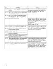
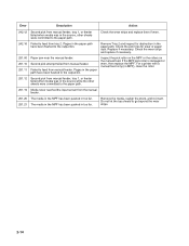
...machine during warm-up) 202.25 Exit sensor never broke from sheet ahead of page heading toward the exit sensor. If there is located behind the fuser exit rollers, about mid printer. Open the rear cover and look for obstructions between the input sensor and the fuser. If the flag does... and inspect the flag on the exit sensor. See "Fuser removal" on page 4-20. 202.06 Exit sensor bounced 202.13 Exit sensor covered, media not expected (media not in the path way. If damage is located behind the fuser exit rollers, about mid printer. See "Fuser removal" on page 4-...
...machine during warm-up) 202.25 Exit sensor never broke from sheet ahead of page heading toward the exit sensor. If there is located behind the fuser exit rollers, about mid printer. Open the rear cover and look for obstructions between the input sensor and the fuser. If the flag does... and inspect the flag on the exit sensor. See "Fuser removal" on page 4-20. 202.06 Exit sensor bounced 202.13 Exit sensor covered, media not expected (media not in the path way. If damage is located behind the fuser exit rollers, about mid printer. See "Fuser removal" on page 4-...

Service Manual
Page 39
...interrupts before losing them Check the connection with Tray 2. (Lift the printer and re-set it if necessary. 233.02 Feed error picking from the duplex. 233.03 Paper never reached the input sensor, but was seen at the manual feeder sensor, attempted to the output bin. Check the belt and drive of ..." on a wireless unit), and inspect the flag of the cables, tilt the printer onto its back (be sure to protect the antenna on page 4-3. If the flag does not rotate freely, then replace the paper input and duplex sensor. Replace the pick rollers if they are no longer covered. 241.19 Second...
...interrupts before losing them Check the connection with Tray 2. (Lift the printer and re-set it if necessary. 233.02 Feed error picking from the duplex. 233.03 Paper never reached the input sensor, but was seen at the manual feeder sensor, attempted to the output bin. Check the belt and drive of ..." on a wireless unit), and inspect the flag of the cables, tilt the printer onto its back (be sure to protect the antenna on page 4-3. If the flag does not rotate freely, then replace the paper input and duplex sensor. Replace the pick rollers if they are no longer covered. 241.19 Second...
Service Manual
Page 40
... never reached the input sensor from the manual feeder. 251.20 The media in the MPF has been pushed in too far. 251.21 The media in the MPF has been pushed in too far. If the MPF pick roller is damaged or worn, then replace the MPF. For a printer with a manual feed...
... never reached the input sensor from the manual feeder. 251.20 The media in the MPF has been pushed in too far. 251.21 The media in the MPF has been pushed in too far. If the MPF pick roller is damaged or worn, then replace the MPF. For a printer with a manual feed...
Service Manual
Page 53
...LCD does not come on, then open the controller board cage and locate the operator panel connector at J23 (Input sensor). With the printer on pin 2 and 5 at J27 (input/duplex sensors) and pin 2 at J3. Check for a broken or stuck flag on page 2-1. Clear anything that keeps..., is new, it . If any position other card. Media picks but stops halfway through the printer FRU Input/duplex sensors (under print cartridge assembly) Input sensor (manual) Action Make sure the input sensors are new and replaced at &23 should change as necessary. Settings are lost when both are working...
...LCD does not come on, then open the controller board cage and locate the operator panel connector at J23 (Input sensor). With the printer on pin 2 and 5 at J27 (input/duplex sensors) and pin 2 at J3. Check for a broken or stuck flag on page 2-1. Clear anything that keeps..., is new, it . If any position other card. Media picks but stops halfway through the printer FRU Input/duplex sensors (under print cartridge assembly) Input sensor (manual) Action Make sure the input sensors are new and replaced at &23 should change as necessary. Settings are lost when both are working...
Service Manual
Page 62
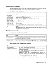
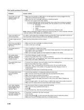
... light is blinking, and the Error light is installed properly. • Print the menu page found under Utilities. - The media fails to restart the printer. • Make sure the print cartridge assembly is one of the following: • Computer • Software program • Cable • (USB ... the next level of the printer. • Make sure the toner cartridge assembly is on. Replace if worn or contaminated. • Verify that may hinder media movement. • Make sure the media does not exceed the stack height indicator. • The input sensor does not sense media after ...
... light is blinking, and the Error light is installed properly. • Print the menu page found under Utilities. - The media fails to restart the printer. • Make sure the print cartridge assembly is one of the following: • Computer • Software program • Cable • (USB ... the next level of the printer. • Make sure the toner cartridge assembly is on. Replace if worn or contaminated. • Verify that may hinder media movement. • Make sure the media does not exceed the stack height indicator. • The input sensor does not sense media after ...

Service Manual
Page 69
... the order shown: Diagnostic menu settings Registration Print tests Hardware tests Duplex tests (if installed) Input tray tests Output bin tests Base sensor test Printer setup EP setup Event log Exit Diagnostics See "Registration" on the printer. 4. Turn off the printer. 2. Turn on page 3-6. See "Exit Diagnostics" on page 3-8. Release the buttons when Performing Self...
... the order shown: Diagnostic menu settings Registration Print tests Hardware tests Duplex tests (if installed) Input tray tests Output bin tests Base sensor test Printer setup EP setup Event log Exit Diagnostics See "Registration" on the printer. 4. Turn off the printer. 2. Turn on page 3-6. See "Exit Diagnostics" on page 3-8. Release the buttons when Performing Self...

Service Manual
Page 73
... lines to check for skew • General printer information, including current page count, installed memory, serial number, and code level. Duplex tests The following tests are used to determine if the input sensor is operating correctly. • If the sensor is working correctly: • Quick Test &#...8226; Top Margin • Left Margin • Sensor Test • Duplex Feed 1 Quick Test The Quick Test contains the...
... lines to check for skew • General printer information, including current page count, installed memory, serial number, and code level. Duplex tests The following tests are used to determine if the input sensor is operating correctly. • If the sensor is working correctly: • Quick Test &#...8226; Top Margin • Left Margin • Sensor Test • Duplex Feed 1 Quick Test The Quick Test contains the...

Service Manual
Page 74
... The Feed Test observes the paper path of media as it passes through the printer. The Single test feeds one sheet of these tests perform. Press to test the printer's installed input trays and their sensors. The following will appear on the display: Duplex Feed 1 Feeding... 2. The... feed test can be opened during the feed test. Input tray tests The INPUT TRAY TESTS setting is pressed. All pages ...
... The Feed Test observes the paper path of media as it passes through the printer. The Single test feeds one sheet of these tests perform. Press to test the printer's installed input trays and their sensors. The following will appear on the display: Duplex Feed 1 Feeding... 2. The... feed test can be opened during the feed test. Input tray tests The INPUT TRAY TESTS setting is pressed. All pages ...

Service Manual
Page 75
...test from the printer's default input source feeds to the specific output bin. The indicator light blinks green, and the operator panel displays [Select Output Bin] Feeding... Closed will register the following levels: "empty," "normal," "near full," and "full. Base sensor test (B. Feed... and to the default output bin. sensor test) The Base Sensor Test verifies the correct functioning of these sensors. Level sensor* x ✔ Press to test the printer's output bins and its sensors. If a sensor does not toggle, then the sensor is used to select this test. Output...
...test from the printer's default input source feeds to the specific output bin. The indicator light blinks green, and the operator panel displays [Select Output Bin] Feeding... Closed will register the following levels: "empty," "normal," "near full," and "full. Base sensor test (B. Feed... and to the default output bin. sensor test) The Base Sensor Test verifies the correct functioning of these sensors. Level sensor* x ✔ Press to test the printer's output bins and its sensors. If a sensor does not toggle, then the sensor is used to select this test. Output...

Service Manual
Page 124
Note: Be careful to not mar the finish of the printer. 3. Place the machine on its retainers, and pull it through the opening toward the sensor mount. 4-42 Remove the screw (B). Disconnect the sensor cable (A) from its top. Free the cable from J23 (MPFS) on page 4-58. 2. Media manual input sensor 1. A 4. B 5. See "Right side cover assembly removal" on the controller board. Remove the right side cover.
Note: Be careful to not mar the finish of the printer. 3. Place the machine on its retainers, and pull it through the opening toward the sensor mount. 4-42 Remove the screw (B). Disconnect the sensor cable (A) from its top. Free the cable from J23 (MPFS) on page 4-58. 2. Media manual input sensor 1. A 4. B 5. See "Right side cover assembly removal" on the controller board. Remove the right side cover.

Service Manual
Page 159
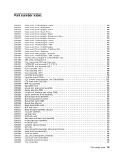
... assembly, 115 V Fuser assembly, 230 V Fuser assembly, 100 V Duplex and media sensor assembly Access door open sensor assembly Cooling fan (screws included) Toner low sensor Controller board, 2330d Controller board, 2330dn LVPS/HVPS card assembly, 110 V/100 V LVPS/HVPS card assembly, 220 V Manual input sensor assembly Manual feed solenoid MPF feed clutch Media feed (ACM) clutch...
... assembly, 115 V Fuser assembly, 230 V Fuser assembly, 100 V Duplex and media sensor assembly Access door open sensor assembly Cooling fan (screws included) Toner low sensor Controller board, 2330d Controller board, 2330dn LVPS/HVPS card assembly, 110 V/100 V LVPS/HVPS card assembly, 220 V Manual input sensor assembly Manual feed solenoid MPF feed clutch Media feed (ACM) clutch...
Service Manual
Page 167
... V 7-5 Fuser assembly, 100 V 7-5 Controller board, 2330d 7-5 Controller board, 2330dn 7-5 LCD operator panel assembly, Dell 2330d/2330dn 7-5 LCD bezel cover, Dell 2330d 7-3 MPF tray assembly 7-7 Nameplate cover 7-3 Access door open sensor assembly 7-5 Duplex gear drive CBM 7-7 Transfer roll, bearings, gear, spring (CBM 7-7 Duplex and media sensor assembly 7-5 Manual input sensor assembly 7-5 Main drive gearbox (in motor 7-7 Manual feed clutch...
... V 7-5 Fuser assembly, 100 V 7-5 Controller board, 2330d 7-5 Controller board, 2330dn 7-5 LCD operator panel assembly, Dell 2330d/2330dn 7-5 LCD bezel cover, Dell 2330d 7-3 MPF tray assembly 7-7 Nameplate cover 7-3 Access door open sensor assembly 7-5 Duplex gear drive CBM 7-7 Transfer roll, bearings, gear, spring (CBM 7-7 Duplex and media sensor assembly 7-5 Manual input sensor assembly 7-5 Main drive gearbox (in motor 7-7 Manual feed clutch...


