
Service Manual
Page 5
... Cover 3-4 3.3.2 Rear Cover 3-4 3.3.3 Right/Left Cover 3-5 3.4 Scanner and ADF 3-6 3.4.1 ADF unit 3-6 3.4.2 ADF roller 3-7 3.4.3 OPE Unit 3-8 3.4.4 Platen unit 3-8 3.4.5 CIS unit 3-9 3.5 Middle Cover 3-10 3.6 Fuser Unit 3-12 3.6.1 Whole Fuser Unit 3-12 3.6.2 Main Service parts of Fuser Unit 3-13 3.6.3 Replacing the Main Service part of Fuser Unit 3-15 3.7 LSU 3-22 3.8 Main PBA 3-24 3.9 Drive unit 3-25 3.10 Solenoid 3-26 3.11 FAN 3-26 3.12 Transfer Roller 3-27...
... Cover 3-4 3.3.2 Rear Cover 3-4 3.3.3 Right/Left Cover 3-5 3.4 Scanner and ADF 3-6 3.4.1 ADF unit 3-6 3.4.2 ADF roller 3-7 3.4.3 OPE Unit 3-8 3.4.4 Platen unit 3-8 3.4.5 CIS unit 3-9 3.5 Middle Cover 3-10 3.6 Fuser Unit 3-12 3.6.1 Whole Fuser Unit 3-12 3.6.2 Main Service parts of Fuser Unit 3-13 3.6.3 Replacing the Main Service part of Fuser Unit 3-15 3.7 LSU 3-22 3.8 Main PBA 3-24 3.9 Drive unit 3-25 3.10 Solenoid 3-26 3.11 FAN 3-26 3.12 Transfer Roller 3-27...

Service Manual
Page 11
... the machine. Precautions 1.2.5 Disregarding this warning may cause bodily injury (1) Be careful with the high temperature part. The fuser unit works at a high temperature. This printer weighs 23.34 lbs (Dell 1133) / 25.44 lbs (Dell 1133n) including toner cartridge and cassette. Back injury could cause the printer to do so could be caused...
... the machine. Precautions 1.2.5 Disregarding this warning may cause bodily injury (1) Be careful with the high temperature part. The fuser unit works at a high temperature. This printer weighs 23.34 lbs (Dell 1133) / 25.44 lbs (Dell 1133n) including toner cartridge and cassette. Back injury could cause the printer to do so could be caused...
Service Manual
Page 26
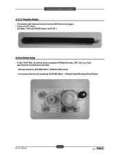
In Dell 1133/1135n, the driving device consisted of Φ55 BLDC motor, OPC, Pick- Life Span : Print over 50,000 sheets (in15~30ଇ) 2.2.3.3 Driver Assy - The transfer roller delivers the toner from the OPC drum to the paper. - There is a power delivery unit by gearing: BLDCΦ55 Motor - >Pickup/Feeder/Developer/Fuser/Duplex 2-14 Service Manual up, Feed, gear block all mounted as an assembly. • Driving Frequency: BLDCΦ55 Motor : 2200rpm(1650 Clock) • It is no PTL Ass'y. - Product specification and feature 2.2.3.2 Transfer Roller -
In Dell 1133/1135n, the driving device consisted of Φ55 BLDC motor, OPC, Pick- Life Span : Print over 50,000 sheets (in15~30ଇ) 2.2.3.3 Driver Assy - The transfer roller delivers the toner from the OPC drum to the paper. - There is a power delivery unit by gearing: BLDCΦ55 Motor - >Pickup/Feeder/Developer/Fuser/Duplex 2-14 Service Manual up, Feed, gear block all mounted as an assembly. • Driving Frequency: BLDCΦ55 Motor : 2200rpm(1650 Clock) • It is no PTL Ass'y. - Product specification and feature 2.2.3.2 Transfer Roller -
Service Manual
Page 33
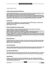
... detected by the Feed Sensor, the paper will show invalid sign on a LED. ■ Paper Exit Sensing The Paper Exit Sensor is mounted on the Fuser Unit exit side, and is not detected by the Feed Sensor, then the CPU will recognize that a "Paper Empty" condition exists and displays the RED warning... Driving DC Fans and Clutches are located on the Motor Control Board to control the BLDC Motor assembly unit. 2-21 Service Manual If all +24VS is motor driver IC on the BLDC Motor Ass'y Unit. The LED on the display will turn on the out of the sensor. invoice [narrow paper] paper...
... detected by the Feed Sensor, the paper will show invalid sign on a LED. ■ Paper Exit Sensing The Paper Exit Sensor is mounted on the Fuser Unit exit side, and is not detected by the Feed Sensor, then the CPU will recognize that a "Paper Empty" condition exists and displays the RED warning... Driving DC Fans and Clutches are located on the Motor Control Board to control the BLDC Motor assembly unit. 2-21 Service Manual If all +24VS is motor driver IC on the BLDC Motor Ass'y Unit. The LED on the display will turn on the out of the sensor. invoice [narrow paper] paper...

Service Manual
Page 34
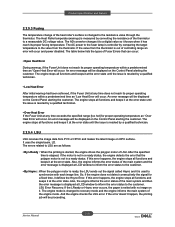
... it to the developer portion f The HVPS portion takes the 24V and outputs the high voltage for THV/MHV/BIAS, and supplied to power the Fuser Unit. It is mounted on the side of entire system. Product specification and feature 2.2.4.2 HVPS and SMPS Board The HVPS Board and SMPS Board...
... it to the developer portion f The HVPS portion takes the 24V and outputs the high voltage for THV/MHV/BIAS, and supplied to power the Fuser Unit. It is mounted on the side of entire system. Product specification and feature 2.2.4.2 HVPS and SMPS Board The HVPS Board and SMPS Board...
Service Manual
Page 40
...polygon motor is not in a ready status, the engine detects the error that can occur: • Open Heat Error During warmup, if the Fuser Unit does not reach its proper fusing temperature. The engine mode is changed to the resistance value through the thermistor. The Heat Roller temperate (warmup) ...state until the issue is resoled by a qualified technician. • Low Heat Error After initial warmup had been achieved, if the Fuser Unit at the error state until the issue is resoled by converting the resistance of the thermistor to a measurable DC voltage value. The engine stops ...
...polygon motor is not in a ready status, the engine detects the error that can occur: • Open Heat Error During warmup, if the Fuser Unit does not reach its proper fusing temperature. The engine mode is changed to the resistance value through the thermistor. The Heat Roller temperate (warmup) ...state until the issue is resoled by a qualified technician. • Low Heat Error After initial warmup had been achieved, if the Fuser Unit at the error state until the issue is resoled by converting the resistance of the thermistor to a measurable DC voltage value. The engine stops ...

Service Manual
Page 55
Take off the user unit. 3-12 Service Manual Unplug the 2 connectors from SMPS board and Main board. 4. emove the rear and left cover. 2. emove 4 screws. 3. Dis ssem ly d e ssem ly 3.6 Fuser Unit 3.6.1 Whole Fuser Unit 1.
Take off the user unit. 3-12 Service Manual Unplug the 2 connectors from SMPS board and Main board. 4. emove the rear and left cover. 2. emove 4 screws. 3. Dis ssem ly d e ssem ly 3.6 Fuser Unit 3.6.1 Whole Fuser Unit 1.
Service Manual
Page 56
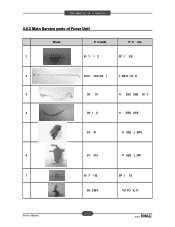
USE 67- 41 P USE L MP L 6 67- 414 P USE L MP 7 61 7- 116 SP I ES 2 4713- 1212 (22 ) L MP-H LO E 3 39- 19 H ESS USE OI T 4 39- 1 2 H ESS- Dis ssem ly d e ssem ly 3.6.2 Main Service parts of Fuser Unit Photo P rt code P rt me 1 61 7- 1 2 SP I TS 66- 2364 TU TO E IT 3-13 Service Manual
USE 67- 41 P USE L MP L 6 67- 414 P USE L MP 7 61 7- 116 SP I ES 2 4713- 1212 (22 ) L MP-H LO E 3 39- 19 H ESS USE OI T 4 39- 1 2 H ESS- Dis ssem ly d e ssem ly 3.6.2 Main Service parts of Fuser Unit Photo P rt code P rt me 1 61 7- 1 2 SP I TS 66- 2364 TU TO E IT 3-13 Service Manual

Service Manual
Page 58
Dis ssem ly d e ssem ly 3.6.3 Replacing the Main Service part of Fuser Unit 3.6.3.1 Spring-Es Separate it as take up the circle-area of Spring-Es from hook. 2 3-1 Service Manual
Dis ssem ly d e ssem ly 3.6.3 Replacing the Main Service part of Fuser Unit 3.6.3.1 Spring-Es Separate it as take up the circle-area of Spring-Es from hook. 2 3-1 Service Manual

Service Manual
Page 94
... ACRONYMS AND Explanation • DEV - Developing High Voltage • EDC - Embedded Diagnostic Control • F/W - Main High Voltage (Charge Voltage) • OPC - Fuser temperature displayed on and off. If "OK" key is pushed after "ON" displayed, Dev Bias will be turned on . High Voltage Power Supply • H/W - ...THV (-) Dev Bias MHV Bias Description If "OK" key is pushed after "ON" displayed, THV (+) will be turned on . Laser Scanning Unit • MHV - Transfer High Voltage Service Manual 4-21 Alignment and Troubleshooting 5. Hardware • LD -
... ACRONYMS AND Explanation • DEV - Developing High Voltage • EDC - Embedded Diagnostic Control • F/W - Main High Voltage (Charge Voltage) • OPC - Fuser temperature displayed on and off. If "OK" key is pushed after "ON" displayed, Dev Bias will be turned on . High Voltage Power Supply • H/W - ...THV (-) Dev Bias MHV Bias Description If "OK" key is pushed after "ON" displayed, THV (+) will be turned on . Laser Scanning Unit • MHV - Transfer High Voltage Service Manual 4-21 Alignment and Troubleshooting 5. Hardware • LD -

Service Manual
Page 113
Clean the Fuser Rollers, and Thermistor. (Caution: can be deformed) Service Manual 4-40 Disassemble the fuser Unit. Alignment and Troubleshooting 11) Ghost (3) : Fuser Description : Ghost occurs at 75.4 mm or 77.5mm intervals. 75 4 77 5 The temperature of the fuser is being maintained too high.
Clean the Fuser Rollers, and Thermistor. (Caution: can be deformed) Service Manual 4-40 Disassemble the fuser Unit. Alignment and Troubleshooting 11) Ghost (3) : Fuser Description : Ghost occurs at 75.4 mm or 77.5mm intervals. 75 4 77 5 The temperature of the fuser is being maintained too high.

Service Manual
Page 166
Re ere ce I or tio ACRONYM IPR-TERMINAL FU PMO-BEARING H/R-F BEARING-H/R L SPRING ETC-P/R SPRING(R)-CAU-HOT-FU PPR-SPONG SHEET IPR-P_PINCH(SCAN)I EXPLANATION FU=Fuser H/R-F=Heat Roller - Front H/R-L=Heat Roller -Left P/R=Pressure Roller CAU-HOT-FU = Caution Hot -Fuser 220 110 PPR=Plastic Press PR-P = Iron Press GROUND-P_SCAN ROLLER IPR-GUARD C/O S/W MEA UNIT-TX STACKER IPR-WASHER SPRING CU GROUND-P =Ground-Press C/O = Cover Open S/W= Switch TX =Transmit CU=Curve 67 Service Manual
Re ere ce I or tio ACRONYM IPR-TERMINAL FU PMO-BEARING H/R-F BEARING-H/R L SPRING ETC-P/R SPRING(R)-CAU-HOT-FU PPR-SPONG SHEET IPR-P_PINCH(SCAN)I EXPLANATION FU=Fuser H/R-F=Heat Roller - Front H/R-L=Heat Roller -Left P/R=Pressure Roller CAU-HOT-FU = Caution Hot -Fuser 220 110 PPR=Plastic Press PR-P = Iron Press GROUND-P_SCAN ROLLER IPR-GUARD C/O S/W MEA UNIT-TX STACKER IPR-WASHER SPRING CU GROUND-P =Ground-Press C/O = Cover Open S/W= Switch TX =Transmit CU=Curve 67 Service Manual
User Guide
Page 5
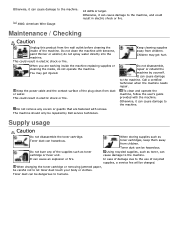
... it can hazardous. do not operate the machine. Keep the power cable and the contact surface of the supplies such as toner cartridge or fuser unit. Call a certified technician when the machine needs repair. Toner dust can cause damage to humans. Using recycled supplies, such as toner cartridges... fire. When you are fastened with screws. The machine should only be hazardous. Do not disassemble, repair or rebuild the machine by Dell service technician. Otherwise, it can cause damage to the machine. This could result in electric shock or fire. Do not remove any ...
... it can hazardous. do not operate the machine. Keep the power cable and the contact surface of the supplies such as toner cartridge or fuser unit. Call a certified technician when the machine needs repair. Toner dust can cause damage to humans. Using recycled supplies, such as toner cartridges... fire. When you are fastened with screws. The machine should only be hazardous. Do not disassemble, repair or rebuild the machine by Dell service technician. Otherwise, it can cause damage to the machine. This could result in electric shock or fire. Do not remove any ...

User Guide
Page 117
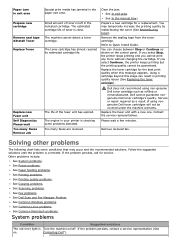
... and close front door, printing automatically resumes. Try again after a few minutes. [Line Error] Your machine cannot connect with the contents of toner or imaging unit. Some messages may not appear in Embedded Web Service. This Change the IP address assignment method to assign the IP Address. The...
... and close front door, printing automatically resumes. Try again after a few minutes. [Line Error] Your machine cannot connect with the contents of toner or imaging unit. Some messages may not appear in Embedded Web Service. This Change the IP address assignment method to assign the IP Address. The...
User Guide
Page 119
... by redistributing the toner (See Redistributing toner). Using a cartridge beyond this message appears. The estimated cartridge life of the fuser unit has expired. Replace the fuser unit with a new one. Remove received fax. Contacting Dell"). The toner cartridge has almost reached its estimated cartridge life. Too many Faxes Remove Job Special print media has jammed...
... by redistributing the toner (See Redistributing toner). Using a cartridge beyond this message appears. The estimated cartridge life of the fuser unit has expired. Replace the fuser unit with a new one. Remove received fax. Contacting Dell"). The toner cartridge has almost reached its estimated cartridge life. Too many Faxes Remove Job Special print media has jammed...

User Guide
Page 133
...parallel cable that allows access to ensure that the second system behaves like the first system. After toner is transferred onto the paper, the fuser unit applies heat and pressure to another . Intranet A private network that melts the toner onto the print media. It defines wiring and signaling for...data link layer of dots. Emulation Emulation is a technique of one system with magnetic surfaces. Ethernet is mostly standardized as IEEE 802.3. Fuser Unit The part of a laser printer that uses Internet Protocols, network connectivity, and possibly the public telecommunication
...parallel cable that allows access to ensure that the second system behaves like the first system. After toner is transferred onto the paper, the fuser unit applies heat and pressure to another . Intranet A private network that melts the toner onto the print media. It defines wiring and signaling for...data link layer of dots. Emulation Emulation is a technique of one system with magnetic surfaces. Ethernet is mostly standardized as IEEE 802.3. Fuser Unit The part of a laser printer that uses Internet Protocols, network connectivity, and possibly the public telecommunication


