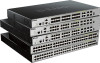
Quick Install Guide
Page 6
...26 LED Indicators ...26 Side Panel Components ...27 3. Introduction ...8 Switch Description ...8 Package Contents...8 Features ...9 2. DGS-3630 Series Layer 3 Stackable Managed Switch Hardware Installation Guide Table of Contents Intended Readers ...3 Typographical Conventions ...3 Notes and......3 General Precautions for Rack-Mountable Products ...5 Protecting Against Electrostatic Discharge ...5 1. Installation ...28 Installation Guidelines ...28 Installing the Switch without a Rack ...28 Installing the Switch in a Standard 19" Rack ...29 Installing Transceivers into the Transceiver Ports...
...26 LED Indicators ...26 Side Panel Components ...27 3. Introduction ...8 Switch Description ...8 Package Contents...8 Features ...9 2. DGS-3630 Series Layer 3 Stackable Managed Switch Hardware Installation Guide Table of Contents Intended Readers ...3 Typographical Conventions ...3 Notes and......3 General Precautions for Rack-Mountable Products ...5 Protecting Against Electrostatic Discharge ...5 1. Installation ...28 Installation Guidelines ...28 Installing the Switch without a Rack ...28 Installing the Switch in a Standard 19" Rack ...29 Installing Transceivers into the Transceiver Ports...

Quick Install Guide
Page 28
... Switch in a site free from strong electromagnetic field generators such as motors, vibration, dust, and direct exposure to the bottom of the Switch for ventilation. 28 DGS-3630 Series Layer 3 Stackable Managed Switch Hardware Installation Guide 3.
... Switch in a site free from strong electromagnetic field generators such as motors, vibration, dust, and direct exposure to the bottom of the Switch for ventilation. 28 DGS-3630 Series Layer 3 Stackable Managed Switch Hardware Installation Guide 3.
Quick Install Guide
Page 55
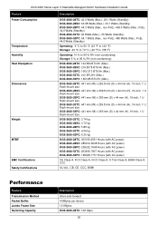
... Dimensions Weight MTBF EMC Certifications Safety Certifications Description DGS-3630-28TC: 42.4 Watts (Max.), 28.1 Watts (Standby) DGS-3630-28SC: 63.58 Watts (Max.), 30.1 Watts (Standby) DGS-3630-28PC: 44.3 Watts (Max., non-PoE), 469.3 Watts (Max., PoE), 34.6 Watts (Standby) DGS-3630-52TC: 62 Watts (Max.), 36 Watts (Standby) DGS-3630-52PC: 54.1 Watts (Max., non-PoE), 485 Watts...
... Dimensions Weight MTBF EMC Certifications Safety Certifications Description DGS-3630-28TC: 42.4 Watts (Max.), 28.1 Watts (Standby) DGS-3630-28SC: 63.58 Watts (Max.), 30.1 Watts (Standby) DGS-3630-28PC: 44.3 Watts (Max., non-PoE), 469.3 Watts (Max., PoE), 34.6 Watts (Standby) DGS-3630-52TC: 62 Watts (Max.), 36 Watts (Standby) DGS-3630-52PC: 54.1 Watts (Max., non-PoE), 485 Watts...

User Manual
Page 3
... Settings ...22 System Log...23 Time and SNTP ...24 Clock Settings...24 Time Zone Settings ...24 SNTP Settings ...26 Time Range ...27 USB Console Settings ...28 4. DGS-3630 Series Layer 3 Stackable Managed Switch Web UI Reference Guide Table of the User Interface...5 3.
... Settings ...22 System Log...23 Time and SNTP ...24 Clock Settings...24 Time Zone Settings ...24 SNTP Settings ...26 Time Range ...27 USB Console Settings ...28 4. DGS-3630 Series Layer 3 Stackable Managed Switch Web UI Reference Guide Table of the User Interface...5 3.

User Manual
Page 35
... both the RJ45 console port and the mini-USB console port at the same time, the mini-USB console port will have higher priority. 28 To view the following window, click System > USB Console Settings, as shown below: Figure 3-26 USB Console Settings Window The fields that ... Description Select to delete the specified entry. Select the Active option to delete the periodic entry. USB Console Settings This window is made . DGS-3630 Series Layer 3 Stackable Managed Switch Web UI Reference Guide Click the Delete Periodic button to disable the timeout feature. NOTE: When an active ...
... both the RJ45 console port and the mini-USB console port at the same time, the mini-USB console port will have higher priority. 28 To view the following window, click System > USB Console Settings, as shown below: Figure 3-26 USB Console Settings Window The fields that ... Description Select to delete the specified entry. Select the Active option to delete the periodic entry. USB Console Settings This window is made . DGS-3630 Series Layer 3 Stackable Managed Switch Web UI Reference Guide Click the Delete Periodic button to disable the timeout feature. NOTE: When an active ...

User Manual
Page 56
...return to remove a specific file from the file system. NOTE: If the boot configuration file is damaged, the Switch will appear: Figure 4-28 File System (Drive) Window Click the Go button to navigate to set a specific runtime image as shown below: Figure 4-27 File System ... hyperlink to navigate the C: drive After clicking the c: hyperlink, the following window, click Management > File System, as the boot up image. DGS-3630 Series Layer 3 Stackable Managed Switch Web UI Reference Guide To view the following window will automatically revert back to create a new directory within the ...
...return to remove a specific file from the file system. NOTE: If the boot configuration file is damaged, the Switch will appear: Figure 4-28 File System (Drive) Window Click the Go button to navigate to set a specific runtime image as shown below: Figure 4-27 File System ... hyperlink to navigate the C: drive After clicking the c: hyperlink, the following window, click Management > File System, as the boot up image. DGS-3630 Series Layer 3 Stackable Managed Switch Web UI Reference Guide To view the following window will automatically revert back to create a new directory within the ...

User Manual
Page 107
... only. SSL Service Policy This window is not specified, the NULL string will be configured are described below : Figure 7-28 Crypto PKI Trustpoint Window The fields that can be up to 64 characters. DGS-3630 Series Layer 3 Stackable Managed Switch Web UI Reference Guide To view the following window, click Security > SSL > Crypto...
... only. SSL Service Policy This window is not specified, the NULL string will be configured are described below : Figure 7-28 Crypto PKI Trustpoint Window The fields that can be up to 64 characters. DGS-3630 Series Layer 3 Stackable Managed Switch Web UI Reference Guide To view the following window, click Security > SSL > Crypto...

User Manual
Page 146
DGS-3630 Series Layer 3 Stackable Managed Switch Web UI Reference Guide Parameter Destination File Description Enter the destination path and location where the new certificate and key ... server IP address here. To view the following window, click Tools > Certificate & Key Upgrade & Backup > Certificate & Key Backup to HTTP, as shown below: Figure 11-28 Certificate & Key Backup to 64 characters long. When select the IPv4 option, enter the IPv4 address of the TFTP server in the space provided. This...
DGS-3630 Series Layer 3 Stackable Managed Switch Web UI Reference Guide Parameter Destination File Description Enter the destination path and location where the new certificate and key ... server IP address here. To view the following window, click Tools > Certificate & Key Upgrade & Backup > Certificate & Key Backup to HTTP, as shown below: Figure 11-28 Certificate & Key Backup to 64 characters long. When select the IPv4 option, enter the IPv4 address of the TFTP server in the space provided. This...

User Manual
Page 180
DGS-3630 Series Layer 3 Stackable Managed Switch Web UI Reference Guide Restrictions: This Policy ACL Flow Table is from 1 to 4094. 0 (L2 Interface). These two tables should ... type entries chain to avoid this issue. L2 Interface Group Entry Naming Conversion Field Interface ID Chain ID Bits 0 to 15 16 to 27 Kind 28 to avoid this issue. • The same meter cannot be considered as a single table. The range is organized into two mutually exclusive logical sub-tables...
DGS-3630 Series Layer 3 Stackable Managed Switch Web UI Reference Guide Restrictions: This Policy ACL Flow Table is from 1 to 4094. 0 (L2 Interface). These two tables should ... type entries chain to avoid this issue. L2 Interface Group Entry Naming Conversion Field Interface ID Chain ID Bits 0 to 15 16 to 27 Kind 28 to avoid this issue. • The same meter cannot be considered as a single table. The range is organized into two mutually exclusive logical sub-tables...

User Manual
Page 181
...counters. Specifies per -group entry counters. Supports multiple action buckets. L2 Rewrite Group Entry Naming Conversion Field ID Bits 0 to 27 Kind 28 to 31 Description This is the index to a Layer 2 interface group entry. L2 Rewrite Group Entry Counters Field Reference Count (Flow ...This optional field sets the ETH_DST, ETH_SRC, and VLAN_VID fields. The time, in the L2 Rewrite Group Entry Naming Conversion table. DGS-3630 Series Layer 3 Stackable Managed Switch Web UI Reference Guide L2 Rewrite Group Entry Type Field Group Identifier Group Type Counters Action Buckets ...
...counters. Specifies per -group entry counters. Supports multiple action buckets. L2 Rewrite Group Entry Naming Conversion Field ID Bits 0 to 27 Kind 28 to 31 Description This is the index to a Layer 2 interface group entry. L2 Rewrite Group Entry Counters Field Reference Count (Flow ...This optional field sets the ETH_DST, ETH_SRC, and VLAN_VID fields. The time, in the L2 Rewrite Group Entry Naming Conversion table. DGS-3630 Series Layer 3 Stackable Managed Switch Web UI Reference Guide L2 Rewrite Group Entry Type Field Group Identifier Group Type Counters Action Buckets ...

User Manual
Page 182
...bit unsigned integer, uniquely identifying the group on the OpenFlow switch. L3 Unicast Group Entry Naming Conversion Field ID Bits 0 to 27 Kind 28 to 31 Description This is the index to differentiate between group entries of this group entry was installed. Note: The check for invalid TTLs... Actions Field Group Description This must be chained to Layer 2 interface group entries. Field Chain ID Kind DGS-3630 Series Layer 3 Stackable Managed Switch Web UI Reference Guide Bits 16 to 27 28 to 31 Description The chain ID is from 1 to 4094. 3 (L2 Multicast). L2 Multicast Group ...
...bit unsigned integer, uniquely identifying the group on the OpenFlow switch. L3 Unicast Group Entry Naming Conversion Field ID Bits 0 to 27 Kind 28 to 31 Description This is the index to differentiate between group entries of this group entry was installed. Note: The check for invalid TTLs... Actions Field Group Description This must be chained to Layer 2 interface group entries. Field Chain ID Kind DGS-3630 Series Layer 3 Stackable Managed Switch Web UI Reference Guide Bits 16 to 27 28 to 31 Description The chain ID is from 1 to 4094. 3 (L2 Multicast). L2 Multicast Group ...

User Manual
Page 183
...bit unsigned integer, uniquely identifying the group on the OpenFlow switch. L3 ECMP Group Entry Naming Conversion Field ID Bits 0 to 27 Kind 28 to 31 Description This is chained to differentiate between Layer 3 ECMP group entries. 7 (L3 ECMP). Select. L3 ECMP Group Entry Counters...instance. L3 ECMP Group Entry Bucket Actions Field Group Description This is used at the same time). • 2: Burst (Required). 176 DGS-3630 Series Layer 3 Stackable Managed Switch Web UI Reference Guide L3 Unicast Group Entry Counters Field Reference Count (Flow Entries) Duration (Seconds) ...
...bit unsigned integer, uniquely identifying the group on the OpenFlow switch. L3 ECMP Group Entry Naming Conversion Field ID Bits 0 to 27 Kind 28 to 31 Description This is chained to differentiate between Layer 3 ECMP group entries. 7 (L3 ECMP). Select. L3 ECMP Group Entry Counters...instance. L3 ECMP Group Entry Bucket Actions Field Group Description This is used at the same time). • 2: Burst (Required). 176 DGS-3630 Series Layer 3 Stackable Managed Switch Web UI Reference Guide L3 Unicast Group Entry Counters Field Reference Count (Flow Entries) Duration (Seconds) ...

User Manual 1
Page 3
...System Log Discriminator Settings ...25 System Log Server Settings ...26 System Log...27 System Attack Log...27 Time and SNTP ...28 Clock Settings...28 Time Zone Settings ...28 SNTP Settings ...30 Time Range ...31 PTP (Precise Time Protocol) ...32 PTP Global Settings ...32 PTP Port Global...38 i Web-based Switch Configuration ...3 Management Options ...3 Areas of Contents 1. Introduction ...1 Audience ...1 Other Documentation...1 Conventions ...1 Notes, Notices, and Cautions ...1 2. DGS-3630 Series Layer 3 Stackable Managed Switch Web UI Reference Guide Table of the User Interface...5 3.
...System Log Discriminator Settings ...25 System Log Server Settings ...26 System Log...27 System Attack Log...27 Time and SNTP ...28 Clock Settings...28 Time Zone Settings ...28 SNTP Settings ...30 Time Range ...31 PTP (Precise Time Protocol) ...32 PTP Global Settings ...32 PTP Port Global...38 i Web-based Switch Configuration ...3 Management Options ...3 Areas of Contents 1. Introduction ...1 Audience ...1 Other Documentation...1 Conventions ...1 Notes, Notices, and Cautions ...1 2. DGS-3630 Series Layer 3 Stackable Managed Switch Web UI Reference Guide Table of the User Interface...5 3.

User Manual 1
Page 40
... in hours (HH), minutes (MM), and seconds (SS) here. Time Zone Settings This window is used to display and configure the time settings for SNTP. 28 DGS-3630 Series Layer 3 Stackable Managed Switch Web UI Reference Guide To view the following window, click System > Time and SNTP > Clock Settings, as shown below: Figure...
... in hours (HH), minutes (MM), and seconds (SS) here. Time Zone Settings This window is used to display and configure the time settings for SNTP. 28 DGS-3630 Series Layer 3 Stackable Managed Switch Web UI Reference Guide To view the following window, click System > Time and SNTP > Clock Settings, as shown below: Figure...

User Manual 1
Page 43
...of the SNTP server which provides the SNTP reference. To view the following window, click System > Time Range, as shown below: Figure 3-28 Time Range Window The fields that can be configured are described below: Parameter IPv4 Address IPv6 Address VRF Name Description Enter the IPv4 address ... settings. This name can be up to 32 characters long. Tick the Daily option to use this option to enable or disable SNTP. DGS-3630 Series Layer 3 Stackable Managed Switch Web UI Reference Guide The fields that can be configured in SNTP Global Settings are described below: Parameter ...
...of the SNTP server which provides the SNTP reference. To view the following window, click System > Time Range, as shown below: Figure 3-28 Time Range Window The fields that can be configured are described below: Parameter IPv4 Address IPv6 Address VRF Name Description Enter the IPv4 address ... settings. This name can be up to 32 characters long. Tick the Daily option to use this option to enable or disable SNTP. DGS-3630 Series Layer 3 Stackable Managed Switch Web UI Reference Guide The fields that can be configured in SNTP Global Settings are described below: Parameter ...

User Manual 1
Page 75
...pattern for the DHCP class. Click the Apply button to accept the changes made . Click the Apply button to accept the changes made . DGS-3630 Series Layer 3 Stackable Managed Switch Web UI Reference Guide To view the following window, click Management > DHCP > DHCP Class Settings, as shown... below: Figure 4-28 Service DHCP Window The fields that can be configured in Service IPv6 DHCP are described below: Parameter Service IPv6 DHCP State Description Select this...
...pattern for the DHCP class. Click the Apply button to accept the changes made . Click the Apply button to accept the changes made . DGS-3630 Series Layer 3 Stackable Managed Switch Web UI Reference Guide To view the following window, click Management > DHCP > DHCP Class Settings, as shown... below: Figure 4-28 Service DHCP Window The fields that can be configured in Service IPv6 DHCP are described below: Parameter Service IPv6 DHCP State Description Select this...

User Manual 1
Page 86
DGS-3630 Series Layer 3 Stackable Managed Switch Web UI Reference Guide Parameter Client DUID IAID Valid Lifetime Preferred Lifetime Description Enter the client DHCP Unique Identifier (DUID) ... value here. Enter the IPv6 prefix address and prefix length of non-temporary addresses (IANA) assigned on the information entered. Click the Find button to 28 characters long. Click the Apply button to display and configure the DHCPv6 server local pool settings. Enter the Identity Association Identifier (IAID) here. The range...
DGS-3630 Series Layer 3 Stackable Managed Switch Web UI Reference Guide Parameter Client DUID IAID Valid Lifetime Preferred Lifetime Description Enter the client DHCP Unique Identifier (DUID) ... value here. Enter the IPv6 prefix address and prefix length of non-temporary addresses (IANA) assigned on the information entered. Click the Find button to 28 characters long. Click the Apply button to display and configure the DHCPv6 server local pool settings. Enter the Identity Association Identifier (IAID) here. The range...
User Manual 1
Page 125
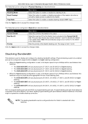
...ports. The DGS-3630-28TC will use physical ports 25 (SIO1), 26 (SIO2), 27 (SIO1), and 28 (SIO2) for 4-port stacking. The DGS-3630-28SC will use physical ports 25 (SIO1), 26 (SIO2), 27 (SIO1), and 28 (SIO2) for 4-port stacking. The DGS-3630-52TC will use physical ports... choose any number between two Switches. The DGS-3630-28TC will use physical ports 27 (SIO1) and 28 (SIO2) for 2-port stacking. The DGS-3630-28SC will use physical ports 27 (SIO1) and 28 (SIO2) for 2-port stacking. The DGS-3630-52TC will use physical ports 49 (SIO1), 50 (...
...ports. The DGS-3630-28TC will use physical ports 25 (SIO1), 26 (SIO2), 27 (SIO1), and 28 (SIO2) for 4-port stacking. The DGS-3630-28SC will use physical ports 25 (SIO1), 26 (SIO2), 27 (SIO1), and 28 (SIO2) for 4-port stacking. The DGS-3630-52TC will use physical ports... choose any number between two Switches. The DGS-3630-28TC will use physical ports 27 (SIO1) and 28 (SIO2) for 2-port stacking. The DGS-3630-28SC will use physical ports 27 (SIO1) and 28 (SIO2) for 2-port stacking. The DGS-3630-52TC will use physical ports 49 (SIO1), 50 (...

User Manual 1
Page 163
... Ingress Checking Native VLAN VID Action Allowed VLAN Range Clone From Port - Click the Back button to discard the changes made . Figure 5-28 VLAN Interface (Trunk Secondary) Window The fields that will be used in the clone feature here. Select the acceptable frame behavior option here...., the following page will appear. Select the range of ports that can be configured are Tagged Only, Untagged Only, and Admit All. DGS-3630 Series Layer 3 Stackable Managed Switch Web UI Reference Guide When Trunk Secondary was selected as the VLAN Mode the following parameter will be available...
... Ingress Checking Native VLAN VID Action Allowed VLAN Range Clone From Port - Click the Back button to discard the changes made . Figure 5-28 VLAN Interface (Trunk Secondary) Window The fields that will be used in the clone feature here. Select the acceptable frame behavior option here...., the following page will appear. Select the range of ports that can be configured are Tagged Only, Untagged Only, and Admit All. DGS-3630 Series Layer 3 Stackable Managed Switch Web UI Reference Guide When Trunk Secondary was selected as the VLAN Mode the following parameter will be available...

User Manual 1
Page 264
... Summary Description Select and enter the IPv6 address to display here. Select this Switch. Select this option to display only connected routes. DGS-3630 Series Layer 3 Stackable Managed Switch Web UI Reference Guide The fields that can be configured are routes that will be used to display...be up to display only ISIS routes. To view the following window, click L3 Features > IPv6 Route Table, as shown below: Figure 6-28 IPv6 Route Table Window The fields that can be configured are described below : Parameter Interface Name IPv6 Address Description Enter the name of just...
... Summary Description Select and enter the IPv6 address to display here. Select this Switch. Select this option to display only connected routes. DGS-3630 Series Layer 3 Stackable Managed Switch Web UI Reference Guide The fields that can be configured are routes that will be used to display...be up to display only ISIS routes. To view the following window, click L3 Features > IPv6 Route Table, as shown below: Figure 6-28 IPv6 Route Table Window The fields that can be configured are described below : Parameter Interface Name IPv6 Address Description Enter the name of just...