Hardware Installation Guide
Page 3
xStack® DGS-3620 Series Layer 3 Managed Stackable Gigabit Switch Hardware Installation Guide Table of Contents Intended Readers ...v Typographical Conventions ...v Notes, Notices, and Cautions ...v Safety Instructions ...vi Safety Precautions ......
xStack® DGS-3620 Series Layer 3 Managed Stackable Gigabit Switch Hardware Installation Guide Table of Contents Intended Readers ...v Typographical Conventions ...v Notes, Notices, and Cautions ...v Safety Instructions ...vi Safety Precautions ......

Hardware Installation Guide
Page 4
Cables and Connectors ...46 Ethernet Cable...46 Console Cable ...47 Redundant Power Supply (RPS) Cable ...48 Warranties & Technical Support ...50 iv xStack® DGS-3620 Series Layer 3 Managed Stackable Gigabit Switch Hardware Installation Guide Appendix A - Technical Specifications ...39 General ...39 Physical and Environmental ...39 Performance ...40 LED Indicators ...41 Port Functions...43 Appendix B -
Cables and Connectors ...46 Ethernet Cable...46 Console Cable ...47 Redundant Power Supply (RPS) Cable ...48 Warranties & Technical Support ...50 iv xStack® DGS-3620 Series Layer 3 Managed Stackable Gigabit Switch Hardware Installation Guide Appendix A - Technical Specifications ...39 General ...39 Physical and Environmental ...39 Performance ...40 LED Indicators ...41 Port Functions...43 Appendix B -
Hardware Installation Guide
Page 5
... loss of the Switch. Do not type the brackets. Indicates a button, a toolbar icon, menu, or menu item. For example: You have initial capitals. xStack® DGS-3620 Series Layer 3 Managed Stackable Gigabit Switch Hardware Installation Guide Intended Readers Intended Readers Typographical Conventions Notes, Notices, and Cautions Safety Instructions General Precautions for Rack... Notes, Notices, and Cautions A NOTE indicates important information that is replaced with network management concepts and terminology. All example screenshots are taken from the DGS-3620-28SC Switch.
... loss of the Switch. Do not type the brackets. Indicates a button, a toolbar icon, menu, or menu item. For example: You have initial capitals. xStack® DGS-3620 Series Layer 3 Managed Stackable Gigabit Switch Hardware Installation Guide Intended Readers Intended Readers Typographical Conventions Notes, Notices, and Cautions Safety Instructions General Precautions for Rack... Notes, Notices, and Cautions A NOTE indicates important information that is replaced with network management concepts and terminology. All example screenshots are taken from the DGS-3620-28SC Switch.
Hardware Installation Guide
Page 6
xStack® DGS-3620 Series Layer 3 Managed Stackable Gigabit Switch Hardware Installation Guide Safety Instructions Use the following safety guidelines to ensure your own personal safety and to help ...
xStack® DGS-3620 Series Layer 3 Managed Stackable Gigabit Switch Hardware Installation Guide Safety Instructions Use the following safety guidelines to ensure your own personal safety and to help ...

Hardware Installation Guide
Page 7
... into the rack. • Do not overload the AC supply branch circuit that suitable grounding is omitted or disconnected. Avoid sudden stops and uneven surfaces. xStack® DGS-3620 Series Layer 3 Managed Stackable Gigabit Switch Hardware Installation Guide • Position system cables and power cables carefully; o Unplug the power cable before extending a component...
... into the rack. • Do not overload the AC supply branch circuit that suitable grounding is omitted or disconnected. Avoid sudden stops and uneven surfaces. xStack® DGS-3620 Series Layer 3 Managed Stackable Gigabit Switch Hardware Installation Guide • Position system cables and power cables carefully; o Unplug the power cable before extending a component...

Hardware Installation Guide
Page 8
... packing material until ready to discharge static electricity from your body before unwrapping the antistatic packaging, be sure to install the component in the system. xStack® DGS-3620 Series Layer 3 Managed Stackable Gigabit Switch Hardware Installation Guide Protecting Against Electrostatic Discharge Static electricity can also be taken prevent damage from electrostatic discharge...
... packing material until ready to discharge static electricity from your body before unwrapping the antistatic packaging, be sure to install the component in the system. xStack® DGS-3620 Series Layer 3 Managed Stackable Gigabit Switch Hardware Installation Guide Protecting Against Electrostatic Discharge Static electricity can also be taken prevent damage from electrostatic discharge...
Hardware Installation Guide
Page 9
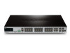
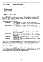
xStack® DGS-3620 Series Layer 3 Managed Stackable Gigabit Switch Hardware Installation Guide Chapter 1 Introduction Switch Description Features Ports Front-Panel Components Rear Panel Description Side Panel Description Switch Description The D-Link DGS-3620 Series is a high performance member of switches: • DGS-3620-28TC: Twenty... (10/100/1000Mbps and 100/1000Mbps), Four SFP+ ports (10GE), Layer 3 Stackable Managed Switch with DC Power. • DGS-3620-28SC: Twenty SFP ports (100/1000Mbps), Four Combo Copper/SFP ports (10/100/1000Mbps and 100/1000Mbps), Four SFP+ ports (10GE...
xStack® DGS-3620 Series Layer 3 Managed Stackable Gigabit Switch Hardware Installation Guide Chapter 1 Introduction Switch Description Features Ports Front-Panel Components Rear Panel Description Side Panel Description Switch Description The D-Link DGS-3620 Series is a high performance member of switches: • DGS-3620-28TC: Twenty... (10/100/1000Mbps and 100/1000Mbps), Four SFP+ ports (10GE), Layer 3 Stackable Managed Switch with DC Power. • DGS-3620-28SC: Twenty SFP ports (100/1000Mbps), Four Combo Copper/SFP ports (10/100/1000Mbps and 100/1000Mbps), Four SFP+ ports (10GE...
Hardware Installation Guide
Page 10
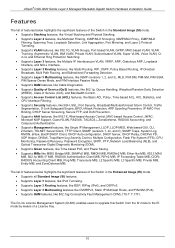
...MIB, Ping MIB, Traceroute MIB, L2 Specific MIB, L3 Specific MIB, Private MIB, Entity MIB, and ZoneDefense MIB. xStack® DGS-3620 Series Layer 3 Managed Stackable Gigabit Switch Hardware Installation Guide Features The list of features below highlights the significant features of ... CPU Interface Filtering. • Supports Security features, like SSH, SSL, Port Security, Broadcast/Multicast/Unicast Storm Control, Traffic Segmentation, D-Link Safeguard Engine, BPDU Attack Protection, ARP Spoofing Prevention, IP-MAC-Port Binding, DHCP Server Screening, Secure FTP, and DoS Prevention. •...
...MIB, Ping MIB, Traceroute MIB, L2 Specific MIB, L3 Specific MIB, Private MIB, Entity MIB, and ZoneDefense MIB. xStack® DGS-3620 Series Layer 3 Managed Stackable Gigabit Switch Hardware Installation Guide Features The list of features below highlights the significant features of ... CPU Interface Filtering. • Supports Security features, like SSH, SSL, Port Security, Broadcast/Multicast/Unicast Storm Control, Traffic Segmentation, D-Link Safeguard Engine, BPDU Attack Protection, ARP Spoofing Prevention, IP-MAC-Port Binding, DHCP Server Screening, Secure FTP, and DoS Prevention. •...
Hardware Installation Guide
Page 11
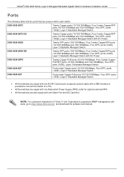
...in D-View, D-Link Corporation's proprietary SNMP management software, go to a PC) • All the switches are equipt with one Redundant Power Supply (RPS) outlet for optional external RPS • All the switches are present within each switch. xStack® DGS-3620 Series Layer 3 ...Managed Stackable Gigabit Switch Hardware Installation Guide Ports The following table lists the ports that are also equipt with DC Power. DGS-3620-28SC Twenty SFP ports (100/1000Mbps), Four Combo Copper...
...in D-View, D-Link Corporation's proprietary SNMP management software, go to a PC) • All the switches are equipt with one Redundant Power Supply (RPS) outlet for optional external RPS • All the switches are present within each switch. xStack® DGS-3620 Series Layer 3 ...Managed Stackable Gigabit Switch Hardware Installation Guide Ports The following table lists the ports that are also equipt with DC Power. DGS-3620-28SC Twenty SFP ports (100/1000Mbps), Four Combo Copper...
Hardware Installation Guide
Page 12
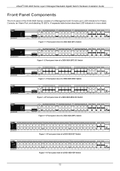
xStack® DGS-3620 Series Layer 3 Managed Stackable Gigabit Switch Hardware Installation Guide Front-Panel Components The front panel of the DGS-3620 Series consists of a DGS-3620-52P Switch 12 Figure 1-1 Front panel view of a DGS-3620-28TC Switch Figure 1-2 Front panel view of a DGS-3620-28TC-DC Switch Figure 1-3 Front panel view of a DGS-3620-28SC Switch Figure 1-4 Front panel view of a DGS-3620-28SC-DC...
xStack® DGS-3620 Series Layer 3 Managed Stackable Gigabit Switch Hardware Installation Guide Front-Panel Components The front panel of the DGS-3620 Series consists of a DGS-3620-52P Switch 12 Figure 1-1 Front panel view of a DGS-3620-28TC Switch Figure 1-2 Front panel view of a DGS-3620-28TC-DC Switch Figure 1-3 Front panel view of a DGS-3620-28SC Switch Figure 1-4 Front panel view of a DGS-3620-28SC-DC...
Hardware Installation Guide
Page 13
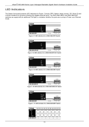
... Power, Console, RPS, Master (stack control), SD, Stack ID and Link/Act indicators for a DGS-3620-28PC Switch 13 Figure 1-7 LED indicators for a DGS-3620-28TC Switch Figure 1-8 LED indicators for a DGS-3620-28TC-DC Switch Figure 1-9 LED indicators for a DGS-3620-28SC Switch Figure 1-10 LED indicators for a DGS-3620-28SC-DC Switch Figure 1-11 LED indicators for all ports including the...
... Power, Console, RPS, Master (stack control), SD, Stack ID and Link/Act indicators for a DGS-3620-28PC Switch 13 Figure 1-7 LED indicators for a DGS-3620-28TC Switch Figure 1-8 LED indicators for a DGS-3620-28TC-DC Switch Figure 1-9 LED indicators for a DGS-3620-28SC Switch Figure 1-10 LED indicators for a DGS-3620-28SC-DC Switch Figure 1-11 LED indicators for all ports including the...
Hardware Installation Guide
Page 14
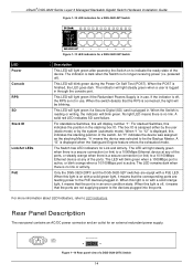
... when the Switch is in use . Only the DGS-3620-28PC and the DGS-3620-52P switches are not supplying power to be blinking. Rear Panel Description The rear panel contains an AC/DC power connector and an outlet for Link and Activity. powered off , the RPS is no... means that the RPS is in . xStack® DGS-3620 Series Layer 3 Managed Stackable Gigabit Switch Hardware Installation Guide Figure 1-12 LED indicators for a DGS-3620-52T Switch Figure 1-13 LED indicators for a DGS-3620-52P Switch LED Power Console RPS SD Stack ID Link/Act LEDs PoE Description This LED will light...
... when the Switch is in use . Only the DGS-3620-28PC and the DGS-3620-52P switches are not supplying power to be blinking. Rear Panel Description The rear panel contains an AC/DC power connector and an outlet for Link and Activity. powered off , the RPS is no... means that the RPS is in . xStack® DGS-3620 Series Layer 3 Managed Stackable Gigabit Switch Hardware Installation Guide Figure 1-12 LED indicators for a DGS-3620-52T Switch Figure 1-13 LED indicators for a DGS-3620-52P Switch LED Power Console RPS SD Stack ID Link/Act LEDs PoE Description This LED will light...
Hardware Installation Guide
Page 15
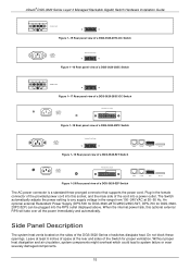
xStack® DGS-3620 Series Layer 3 Managed Stackable Gigabit Switch Hardware Installation Guide Figure 1-15 Rear panel view of a DGS-3620-28TC-DC Switch Figure 1-16 Rear panel view of a DGS-3620-28SC Switch Figure 1-17 Rear panel view of a DGS-3620-28SC-DC Switch Figure 1-18 Rear panel view of a DGS-3620-28PC Switch Figure 1-19 Rear panel view of a DGS-3620...Redundant Power Supply (DPS-500 for DGS-3620-28TC/28SC/26SC/52T, DPS-700 for proper ventilation. Side Panel Description The system heat vents located on the sides of the DGS-3620-Series of a DGS-3620-52P Switch The AC power connector...
xStack® DGS-3620 Series Layer 3 Managed Stackable Gigabit Switch Hardware Installation Guide Figure 1-15 Rear panel view of a DGS-3620-28TC-DC Switch Figure 1-16 Rear panel view of a DGS-3620-28SC Switch Figure 1-17 Rear panel view of a DGS-3620-28SC-DC Switch Figure 1-18 Rear panel view of a DGS-3620-28PC Switch Figure 1-19 Rear panel view of a DGS-3620...Redundant Power Supply (DPS-500 for DGS-3620-28TC/28SC/26SC/52T, DPS-700 for proper ventilation. Side Panel Description The system heat vents located on the sides of the DGS-3620-Series of a DGS-3620-52P Switch The AC power connector...
Hardware Installation Guide
Page 16
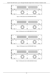
xStack® DGS-3620 Series Layer 3 Managed Stackable Gigabit Switch Hardware Installation Guide Figure 1-21 Side panels view of a DGS-3620-28TC Switch Figure 1-22 Side panels view of a DGS-3620-28TC-DC Switch Figure 1-23 Side panels view of a DGS-3620-28SC Switch Figure 1-24 Side panels view of a DGS-3620-28SC-DC Switch 16
xStack® DGS-3620 Series Layer 3 Managed Stackable Gigabit Switch Hardware Installation Guide Figure 1-21 Side panels view of a DGS-3620-28TC Switch Figure 1-22 Side panels view of a DGS-3620-28TC-DC Switch Figure 1-23 Side panels view of a DGS-3620-28SC Switch Figure 1-24 Side panels view of a DGS-3620-28SC-DC Switch 16

Hardware Installation Guide
Page 17
xStack® DGS-3620 Series Layer 3 Managed Stackable Gigabit Switch Hardware Installation Guide Figure 1-25 Side panels view of a DGS-3620-28PC Switch Figure 1-26 Side panels view of a DGS-3620-52T Switch Figure 1-27 Side panels view of a DGS-3620-52P Switch 17
xStack® DGS-3620 Series Layer 3 Managed Stackable Gigabit Switch Hardware Installation Guide Figure 1-25 Side panels view of a DGS-3620-28PC Switch Figure 1-26 Side panels view of a DGS-3620-52T Switch Figure 1-27 Side panels view of a DGS-3620-52P Switch 17

Hardware Installation Guide
Page 18
...the Switch. • The power outlet should be within 1.82 meters (6 feet) of space at least 6.6 lb. (3kg - xStack® DGS-3620 Series Layer 3 Managed Stackable Gigabit Switch Hardware Installation Guide Chapter 2 Installation Package Contents Installation Guidelines Power On (AC Power) Alarm Connector ...guide/Web UI reference guide/Hardware Installation Guide/D-View module If any item is missing or damaged, please contact your local D-Link Reseller for the acceptable temperature and humidity operating ranges. • Install the Switch in a site free from strong electromagnetic field...
...the Switch. • The power outlet should be within 1.82 meters (6 feet) of space at least 6.6 lb. (3kg - xStack® DGS-3620 Series Layer 3 Managed Stackable Gigabit Switch Hardware Installation Guide Chapter 2 Installation Package Contents Installation Guidelines Power On (AC Power) Alarm Connector ...guide/Web UI reference guide/Hardware Installation Guide/D-View module If any item is missing or damaged, please contact your local D-Link Reseller for the acceptable temperature and humidity operating ranges. • Install the Switch in a site free from strong electromagnetic field...

Hardware Installation Guide
Page 19
... space around the Switch to a standard 19" rack using the screws provided. Attaching Brackets to a Switch for proper air flow, ventilation and cooling. 19 xStack® DGS-3620 Series Layer 3 Managed Stackable Gigabit Switch Hardware Installation Guide Installing the Switch without a Rack First, attach the rubber feet included with the Switch if installing...
... space around the Switch to a standard 19" rack using the screws provided. Attaching Brackets to a Switch for proper air flow, ventilation and cooling. 19 xStack® DGS-3620 Series Layer 3 Managed Stackable Gigabit Switch Hardware Installation Guide Installing the Switch without a Rack First, attach the rubber feet included with the Switch if installing...
Hardware Installation Guide
Page 20
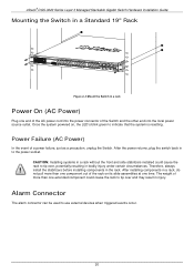
... of more than one extended component could cause the rack to tip over and may result in a rack Power On (AC Power) Plug one time. xStack® DGS-3620 Series Layer 3 Managed Stackable Gigabit Switch Hardware Installation Guide Mounting the Switch in a Standard 19" Rack Figure 2-3 Mount the Switch in injury. After installing...
... of more than one extended component could cause the rack to tip over and may result in a rack Power On (AC Power) Plug one time. xStack® DGS-3620 Series Layer 3 Managed Stackable Gigabit Switch Hardware Installation Guide Mounting the Switch in a Standard 19" Rack Figure 2-3 Mount the Switch in injury. After installing...
Hardware Installation Guide
Page 21
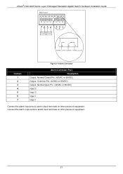
Normal Closed Pin. (42VAC or 60VDC) Output. xStack® DGS-3620 Series Layer 3 Managed Stackable Gigabit Switch Hardware Installation Guide Figure 2-4 Alarm Connector Contact 1 2 3 4 5 6 7 Alarm Connector Port Description Output. Common Pin. (42VAC or 60VDC) Output. Connect the alarm output pins to alarm output terminals on other pieces of equipment. 21 Normal Open Pin. (42VAC or 60VDC) Input 2 Input 2 Input 1 Input 1 Connect the alarm input pins to alarm input terminals on other pieces of equipment.
Normal Closed Pin. (42VAC or 60VDC) Output. xStack® DGS-3620 Series Layer 3 Managed Stackable Gigabit Switch Hardware Installation Guide Figure 2-4 Alarm Connector Contact 1 2 3 4 5 6 7 Alarm Connector Port Description Output. Common Pin. (42VAC or 60VDC) Output. Connect the alarm output pins to alarm output terminals on other pieces of equipment. 21 Normal Open Pin. (42VAC or 60VDC) Input 2 Input 2 Input 1 Input 1 Connect the alarm input pins to alarm input terminals on other pieces of equipment.
Hardware Installation Guide
Page 22
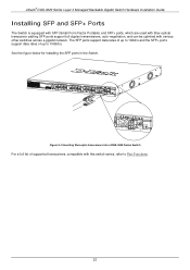
See the figure below for installing the SFP ports in the Switch. Figure 2-5 Inserting fiber-optic transceivers into a DGS-3620 Series Switch For a full list of up to Port Functions. 22 xStack® DGS-3620 Series Layer 3 Managed Stackable Gigabit Switch Hardware Installation Guide Installing SFP and SFP+ Ports The Switch is equipped with SFP (Small...
See the figure below for installing the SFP ports in the Switch. Figure 2-5 Inserting fiber-optic transceivers into a DGS-3620 Series Switch For a full list of up to Port Functions. 22 xStack® DGS-3620 Series Layer 3 Managed Stackable Gigabit Switch Hardware Installation Guide Installing SFP and SFP+ Ports The Switch is equipped with SFP (Small...