Quick Install Guide
Page 3
... Command Line Interface (CLI) ...25 Connecting to the Console Port ...25 Logging into the Web UI ...27 Web Interface Navigation ...28 SNMP-based Management ...29 Connecting using SNMP ...29 Traps...29 Management Information Base (MIB) ...29 Appendix A - Switch Connections ...20... Front Panel LED Indicators ...4 Rear Panel Components ...6 Rear Panel LED Indicators ...8 Side Panel Components ...9 Smart Fans ...10 3. DGS-1520 Series Gigabit Ethernet Smart Managed Switch Hardware Installation Guide Table of Contents Intended Readers ...v Typographical Conventions ...v Notes and Cautions ...v 1.
... Command Line Interface (CLI) ...25 Connecting to the Console Port ...25 Logging into the Web UI ...27 Web Interface Navigation ...28 SNMP-based Management ...29 Connecting using SNMP ...29 Traps...29 Management Information Base (MIB) ...29 Appendix A - Switch Connections ...20... Front Panel LED Indicators ...4 Rear Panel Components ...6 Rear Panel LED Indicators ...8 Side Panel Components ...9 Smart Fans ...10 3. DGS-1520 Series Gigabit Ethernet Smart Managed Switch Hardware Installation Guide Table of Contents Intended Readers ...v Typographical Conventions ...v Notes and Cautions ...v 1.
Quick Install Guide
Page 6
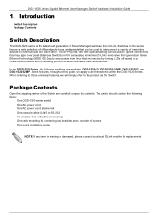
...be used to interconnect a variety of networking devices to uplink connections that are available: DGS-1520-28, DGS-1520-28MP, DGS-1520-52, and DGS-1520-52MP. In the DGS-1520 Series, the following items: • One DGS-1520 series switch • One AC power cord • One AC power cord retainer ...) • Four rubber feet with each other. Introduction Switch Description Package Contents Switch Description The DGS-1520 series is missing or damaged, please contact your local D-Link reseller for replacement. 1 Switches in this series feature a wide selection of screws • One...
...be used to interconnect a variety of networking devices to uplink connections that are available: DGS-1520-28, DGS-1520-28MP, DGS-1520-52, and DGS-1520-52MP. In the DGS-1520 Series, the following items: • One DGS-1520 series switch • One AC power cord • One AC power cord retainer ...) • Four rubber feet with each other. Introduction Switch Description Package Contents Switch Description The DGS-1520 series is missing or damaged, please contact your local D-Link reseller for replacement. 1 Switches in this series feature a wide selection of screws • One...
Quick Install Guide
Page 7
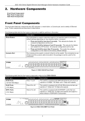
.... This reboots the Switch. This reboots the Switch and restarts the ZTP function. Figure 2-2 DGS-1520-28MP Front Panel 2 This following table lists the front panel components unique to the DGS-1520-28: Port Type Port Number Description RJ45 Ports (10/100/1000 Mbps) Ports 1 to the ...SFP+ transceivers. These components are described in the package) must be lost . • Press and hold for the connection. Figure 2-1 DGS-1520-28 Front Panel This following table lists the front panel components on all the switches in the series: Port Description Reset Button The reset button ...
.... This reboots the Switch. This reboots the Switch and restarts the ZTP function. Figure 2-2 DGS-1520-28MP Front Panel 2 This following table lists the front panel components unique to the DGS-1520-28: Port Type Port Number Description RJ45 Ports (10/100/1000 Mbps) Ports 1 to the ...SFP+ transceivers. These components are described in the package) must be lost . • Press and hold for the connection. Figure 2-1 DGS-1520-28 Front Panel This following table lists the front panel components on all the switches in the series: Port Description Reset Button The reset button ...
Quick Install Guide
Page 8
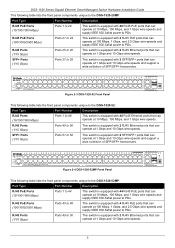
...components unique to the DGS-1520-52MP: Port Type Port Number Description RJ45 PoE Ports (10/100/1000 Mbps) Ports 1 to 44 This switch is equipped with 2 RJ45 Ethernet ports that can operate at 1 Gbps and 10 Gbps wire-speeds. SFP+ Ports (1/10 Gbps) Ports 27 to 28 This switch is ... at 1 Gbps and 10 Gbps wire-speeds and support a wide collection of SFP/SFP+ transceivers. Figure 2-3 DGS-1520-52 Front Panel This following table lists the front panel components unique to the DGS-1520-52: Port Type Port Number Description RJ45 Ports (10/100/1000 Mbps) Ports 1 to 48 This switch is...
...components unique to the DGS-1520-52MP: Port Type Port Number Description RJ45 PoE Ports (10/100/1000 Mbps) Ports 1 to 44 This switch is equipped with 2 RJ45 Ethernet ports that can operate at 1 Gbps and 10 Gbps wire-speeds. SFP+ Ports (1/10 Gbps) Ports 27 to 28 This switch is ... at 1 Gbps and 10 Gbps wire-speeds and support a wide collection of SFP/SFP+ transceivers. Figure 2-3 DGS-1520-52 Front Panel This following table lists the front panel components unique to the DGS-1520-52: Port Type Port Number Description RJ45 Ports (10/100/1000 Mbps) Ports 1 to 48 This switch is...

Quick Install Guide
Page 9
Figure 2-5 DGS-1520-28 Front Panel LED Indicators Figure 2-6 DGS-1520-28MP Front Panel LED Indicators Figure 2-7 DGS-1520-52 Front Panel LED Indicators Figure 2-8 DGS-1520-52MP Front Panel LED Indicators The front panel LED indicators (per device) are described in the following table: LED Color ... operate at 1 Gbps and 10 Gbps wire-speeds and support a wide collection of ways like their color, blinking times, and location. DGS-1520 Series Gigabit Ethernet Smart Managed Switch Hardware Installation Guide Port Type SFP+ Ports (1/10 Gbps) Port Number Ports 51 to 52 Description This ...
Figure 2-5 DGS-1520-28 Front Panel LED Indicators Figure 2-6 DGS-1520-28MP Front Panel LED Indicators Figure 2-7 DGS-1520-52 Front Panel LED Indicators Figure 2-8 DGS-1520-52MP Front Panel LED Indicators The front panel LED indicators (per device) are described in the following table: LED Color ... operate at 1 Gbps and 10 Gbps wire-speeds and support a wide collection of ways like their color, blinking times, and location. DGS-1520 Series Gigabit Ethernet Smart Managed Switch Hardware Installation Guide Port Type SFP+ Ports (1/10 Gbps) Port Number Ports 51 to 52 Description This ...
Quick Install Guide
Page 11
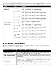
...power at 50-60 Hz. Then, lights solid green until the system is ready. Fan LED Lights solid green when the switch is ready. Link/Act Mode Lights solid green when the switch is powered on . Rear Panel Components The rear panel features components like an AC power socket, a... Fan LED Lights solid green when the switch is powered on . LED Then, returns to secure the lock. This following table: Switch LED(s) Behavior DGS-1520-28 DGS-1520-52 Power LED Blinks green when the switch is ready. Switch GND Use an electrical grounding wire and connect one end of the wire to...
...power at 50-60 Hz. Then, lights solid green until the system is ready. Fan LED Lights solid green when the switch is ready. Link/Act Mode Lights solid green when the switch is powered on . Rear Panel Components The rear panel features components like an AC power socket, a... Fan LED Lights solid green when the switch is powered on . LED Then, returns to secure the lock. This following table: Switch LED(s) Behavior DGS-1520-28 DGS-1520-52 Power LED Blinks green when the switch is ready. Switch GND Use an electrical grounding wire and connect one end of the wire to...
Quick Install Guide
Page 12
...main power source or as the secondary power source to the Switch. DGS-1520 Series Gigabit Ethernet Smart Managed Switch Hardware Installation Guide Figure 2-9 DGS-1520-28 Rear Panel This following table lists the front panel components unique to the DGS-1520-28: Port Description MGMT Port (PoH IN Port) The RJ45 Management ...(MGMT) port is an IP-based, Out-Of-Band (OOB) port for Telnet, Web, or SNMP management that operates at 10/100/1000 Mbps wirespeed. Figure 2-11 DGS-1520-52 Rear Panel ...
...main power source or as the secondary power source to the Switch. DGS-1520 Series Gigabit Ethernet Smart Managed Switch Hardware Installation Guide Figure 2-9 DGS-1520-28 Rear Panel This following table lists the front panel components unique to the DGS-1520-28: Port Description MGMT Port (PoH IN Port) The RJ45 Management ...(MGMT) port is an IP-based, Out-Of-Band (OOB) port for Telnet, Web, or SNMP management that operates at 10/100/1000 Mbps wirespeed. Figure 2-11 DGS-1520-52 Rear Panel ...

Quick Install Guide
Page 13
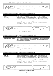
... Supply The RPS port can be used to connect an optional external load-sharing RPS to the Switch. When a PSE is present 8 Figure 2-13 DGS-1520-28/52 Rear Panel LED Indicators The rear panel LED indicators (per device) are described in a variety of ways like their color, blinking times, and ...connection at 10/100 Mbps through the MGMT port On (Blinking) Data transmitted and received through the MGMT port Off Off Inactive connection or no link present PD Green On (Solid) Receiving DC power from PoH PSE connected to the MGMT port Amber On (Solid) Normal MGMT connection active (no...
... Supply The RPS port can be used to connect an optional external load-sharing RPS to the Switch. When a PSE is present 8 Figure 2-13 DGS-1520-28/52 Rear Panel LED Indicators The rear panel LED indicators (per device) are described in a variety of ways like their color, blinking times, and ...connection at 10/100 Mbps through the MGMT port On (Blinking) Data transmitted and received through the MGMT port Off Off Inactive connection or no link present PD Green On (Solid) Receiving DC power from PoH PSE connected to the MGMT port Amber On (Solid) Normal MGMT connection active (no...
Quick Install Guide
Page 14
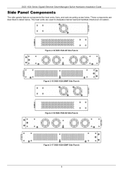
Figure 2-14 DGS-1520-28 Side Panels Figure 2-15 DGS-1520-28MP Side Panels Figure 2-16 DGS-1520-52 Side Panels Figure 2-17 DGS-1520-52MP Side Panels 9 These components are used to dissipate internal heat and facilitate internal air circulation. DGS-1520 Series Gigabit Ethernet Smart Managed Switch Hardware Installation Guide Side Panel Components The side panels feature components like heat vents, fans, and rack-mounting screw holes. The heat vents are described in detail below.
Figure 2-14 DGS-1520-28 Side Panels Figure 2-15 DGS-1520-28MP Side Panels Figure 2-16 DGS-1520-52 Side Panels Figure 2-17 DGS-1520-52MP Side Panels 9 These components are used to dissipate internal heat and facilitate internal air circulation. DGS-1520 Series Gigabit Ethernet Smart Managed Switch Hardware Installation Guide Side Panel Components The side panels feature components like heat vents, fans, and rack-mounting screw holes. The heat vents are described in detail below.

Quick Install Guide
Page 15
...automatically change : Module Low Speed Medium Speed DGS-1520-28 Below 30°C Above 33°C / Below 37°C DGS-1520-28MP Below 30°C Above 33°C / Below 37°C DGS-1520-52 Below 30°C Above 33°C / Below 37°C DGS-1520-52MP Below 30°C Above 33°C...High Speed Above 40°C Above 40°C Above 40°C Above 40°C 10 DGS-1520 Series Gigabit Ethernet Smart Managed Switch Hardware Installation Guide Smart Fans The DGS-1520 Series Switches includes smart fans that will change their speed depending on the internal temperature detected ...
...automatically change : Module Low Speed Medium Speed DGS-1520-28 Below 30°C Above 33°C / Below 37°C DGS-1520-28MP Below 30°C Above 33°C / Below 37°C DGS-1520-52 Below 30°C Above 33°C / Below 37°C DGS-1520-52MP Below 30°C Above 33°C...High Speed Above 40°C Above 40°C Above 40°C Above 40°C 10 DGS-1520 Series Gigabit Ethernet Smart Managed Switch Hardware Installation Guide Smart Fans The DGS-1520 Series Switches includes smart fans that will change their speed depending on the internal temperature detected ...

Quick Install Guide
Page 22
...Link DPS-520 Managed PSE is installed to prevent cable damage. Cela pourrait endommager l'alimentation électrique interne. ATTENTION: Laissez un espace d'au moins 15 cm (6 pouces) à l'arrière du commutateur lorsqu'un RPS est installé pour éviter d'endommager les câbles. 17 NOTE: Only the DGS-1520-28 and DGS-1520...-52 feature a MGMT PoH-capable port on the Switch (at the bottom) to the Switch from the PSE (at the top). DGS-1520 Series Gigabit Ethernet Smart Managed Switch Hardware Installation Guide...
...Link DPS-520 Managed PSE is installed to prevent cable damage. Cela pourrait endommager l'alimentation électrique interne. ATTENTION: Laissez un espace d'au moins 15 cm (6 pouces) à l'arrière du commutateur lorsqu'un RPS est installé pour éviter d'endommager les câbles. 17 NOTE: Only the DGS-1520-28 and DGS-1520...-52 feature a MGMT PoH-capable port on the Switch (at the bottom) to the Switch from the PSE (at the top). DGS-1520 Series Gigabit Ethernet Smart Managed Switch Hardware Installation Guide...

Quick Install Guide
Page 25
...DGS-1520-28 Port 27 Port 28 40 Gbps (full-duplex) DGS-1520-28MP Port 27 Port 28 40 Gbps (full-duplex) DGS-1520-52 Port 51 Port 52 40 Gbps (full-duplex) DGS-1520-52MP Port 51 Port 52 40 Gbps (full-duplex) 4-port DGS-1520-28 Port 25 and 26 Port 27 and 28 80 Gbps (full-duplex) DGS-1520...-link format. Up to eight switches can physically be transferred through the stacking cables between switches in two directions. Switch Connections Stacking the Switch Switch to Switch Switch to Server Switch to another Switch in one connection to any of the Switch. DGS-1520 ...
...DGS-1520-28 Port 27 Port 28 40 Gbps (full-duplex) DGS-1520-28MP Port 27 Port 28 40 Gbps (full-duplex) DGS-1520-52 Port 51 Port 52 40 Gbps (full-duplex) DGS-1520-52MP Port 51 Port 52 40 Gbps (full-duplex) 4-port DGS-1520-28 Port 25 and 26 Port 27 and 28 80 Gbps (full-duplex) DGS-1520...-link format. Up to eight switches can physically be transferred through the stacking cables between switches in two directions. Switch Connections Stacking the Switch Switch to Switch Switch to Server Switch to another Switch in one connection to any of the Switch. DGS-1520 ...

Quick Install Guide
Page 33
.... Some management functions like Save, Tools, Online Help, customized Language preferences, and a Logout option is displayed on the selections made in Area 3. 28 AREA 2 In this area, a graphical near real-time image of the front panel of features. AREA 3 In this toolbar. The user account ...Web UI to easily find the link to the set of the Switch is displayed with access to functions like port monitoring are described in the table below: Area Number Function AREA 1 In this area, a toolbar with ports and expansion modules. DGS-1520 Series Gigabit Ethernet Smart Managed ...
.... Some management functions like Save, Tools, Online Help, customized Language preferences, and a Logout option is displayed on the selections made in Area 3. 28 AREA 2 In this area, a graphical near real-time image of the front panel of features. AREA 3 In this toolbar. The user account ...Web UI to easily find the link to the set of the Switch is displayed with access to functions like port monitoring are described in the table below: Area Number Function AREA 1 In this area, a toolbar with ports and expansion modules. DGS-1520 Series Gigabit Ethernet Smart Managed ...

Quick Install Guide
Page 35
...-inch, 1 U Rack-mount size DGS-1520-28 2.33 kg DGS-1520-28MP 4.29 kg DGS-1520-52 2.78 kg DGS-1520-52MP 4.80 kg DGS-1520-28 100~240 VAC, 50~60 Hz, 0.8 A Max DGS-1520-28MP 100~240 VAC, 50~60 Hz, 5.5 A Max DGS-1520-52 100~240 VAC, 50~60 Hz, 1.0 A Max DGS-1520-52MP 100~240 VAC, 50~60 Hz, 6.0 A Max DGS-1520-28 DGS-1520-52 Optional RPS through...
...-inch, 1 U Rack-mount size DGS-1520-28 2.33 kg DGS-1520-28MP 4.29 kg DGS-1520-52 2.78 kg DGS-1520-52MP 4.80 kg DGS-1520-28 100~240 VAC, 50~60 Hz, 0.8 A Max DGS-1520-28MP 100~240 VAC, 50~60 Hz, 5.5 A Max DGS-1520-52 100~240 VAC, 50~60 Hz, 1.0 A Max DGS-1520-52MP 100~240 VAC, 50~60 Hz, 6.0 A Max DGS-1520-28 DGS-1520-52 Optional RPS through...

Quick Install Guide
Page 36
...to 16K entries (512 static MAC addresses) Store and forward DGS-1520-28 2 MB DGS-1520-28MP 2 MB DGS-1520-52 2 MB (x2) DGS-1520-52MP 2 MB (x2) DGS-1520-28 95.24 Mpps DGS-1520-28MP 104.16 Mpps 31 DGS-1520 Series Gigabit Ethernet Smart Managed Switch Hardware Installation Guide Power Consumption...Capacity MAC Address Table Transmission Method Packet Buffer Packet Forwarding Rate (Maximum) Performance Specification Description DGS-1520-28 128 Gbps DGS-1520-28MP 140 Gbps DGS-1520-52 176 Gbps DGS-1520-52MP 188 Gbps Up to a secure immovable device. Insert the lock into the notch ...
...to 16K entries (512 static MAC addresses) Store and forward DGS-1520-28 2 MB DGS-1520-28MP 2 MB DGS-1520-52 2 MB (x2) DGS-1520-52MP 2 MB (x2) DGS-1520-28 95.24 Mpps DGS-1520-28MP 104.16 Mpps 31 DGS-1520 Series Gigabit Ethernet Smart Managed Switch Hardware Installation Guide Power Consumption...Capacity MAC Address Table Transmission Method Packet Buffer Packet Forwarding Rate (Maximum) Performance Specification Description DGS-1520-28 128 Gbps DGS-1520-28MP 140 Gbps DGS-1520-52 176 Gbps DGS-1520-52MP 188 Gbps Up to a secure immovable device. Insert the lock into the notch ...

Quick Install Guide
Page 38
...1000BASE-T) IEEE 802.3x (Full-Duplex, Flow Control) The following classifications apply to IEEE 802.3af/at with a minimum voltage output of D-Link transceivers that are backwards compatible to support SFP transceivers. The PoE ports on page 33. Standards Power over HDBaseT power to the Switch. ...Single-mode 50 km 33 TX RX 1310 nm 850 nm 1310 nm 1550 nm DGS-1520 Series Gigabit Ethernet Smart Managed Switch Hardware Installation Guide PoE Ports (DGS-1520-28MP/52MP Only) MGMT Port (DGS-1520-28/52 Only) Port Type Specifications All SFP+ port are supported on the Switch, ...
...1000BASE-T) IEEE 802.3x (Full-Duplex, Flow Control) The following classifications apply to IEEE 802.3af/at with a minimum voltage output of D-Link transceivers that are backwards compatible to support SFP transceivers. The PoE ports on page 33. Standards Power over HDBaseT power to the Switch. ...Single-mode 50 km 33 TX RX 1310 nm 850 nm 1310 nm 1550 nm DGS-1520 Series Gigabit Ethernet Smart Managed Switch Hardware Installation Guide PoE Ports (DGS-1520-28MP/52MP Only) MGMT Port (DGS-1520-28/52 Only) Port Type Specifications All SFP+ port are supported on the Switch, ...

Quick Install Guide
Page 43
...Only hardware-based ERPS supports the Fast Link Drop Interrupt feature with a recovery time of 50 milliseconds in a 16-node ring. DGS-1520 Series Gigabit Ethernet Smart Managed Switch Hardware Installation Guide Appendix C - Model Name DGS-1520-28 ERPS Hardware-based Software-based Port 1... to 8 V Port 9 to 26 V Port 27 to 28 V Model Name DGS-1520-28MP ERPS Hardware-based Software-based...
...Only hardware-based ERPS supports the Fast Link Drop Interrupt feature with a recovery time of 50 milliseconds in a 16-node ring. DGS-1520 Series Gigabit Ethernet Smart Managed Switch Hardware Installation Guide Appendix C - Model Name DGS-1520-28 ERPS Hardware-based Software-based Port 1... to 8 V Port 9 to 26 V Port 27 to 28 V Model Name DGS-1520-28MP ERPS Hardware-based Software-based...

User Manual
Page 3
DGS-1520 Series Gigabit Ethernet Smart Managed Switch Web UI Reference Guide Table of Contents 1. System ...7 Device Information ...7 System Information Settings...8 Peripheral Settings ...9 Port Configuration ...10 Port ... Measurement...22 PoE LLDP Classification...23 System Log ...24 System Log Settings...24 System Log Discriminator Settings ...26 System Log Server Settings ...27 System Log...28 System Attack Log...29 Time and SNTP ...29 Clock Settings...29 Time Zone Settings ...30 SNTP Settings ...31 Time Range ...32 Reset Button Settings ...33...
DGS-1520 Series Gigabit Ethernet Smart Managed Switch Web UI Reference Guide Table of Contents 1. System ...7 Device Information ...7 System Information Settings...8 Peripheral Settings ...9 Port Configuration ...10 Port ... Measurement...22 PoE LLDP Classification...23 System Log ...24 System Log Settings...24 System Log Discriminator Settings ...26 System Log Server Settings ...27 System Log...28 System Attack Log...29 Time and SNTP ...29 Clock Settings...29 Time Zone Settings ...30 SNTP Settings ...31 Time Range ...32 Reset Button Settings ...33...

User Manual
Page 18
... Gigabit Ethernet Smart Managed Switch Web UI Reference Guide System Information Settings This window is only available on the DGS-1520-28 and DGS-1520-52. Enter the description for this interface here. The Management Interface section is used to enable or disable the state of the Switch, if so ...
... Gigabit Ethernet Smart Managed Switch Web UI Reference Guide System Information Settings This window is only available on the DGS-1520-28 and DGS-1520-52. Enter the description for this interface here. The Management Interface section is used to enable or disable the state of the Switch, if so ...

User Manual
Page 38
Click the Delete button to clear the system log entries displayed in the table. DGS-1520 Series Gigabit Ethernet Smart Managed Switch Web UI Reference Guide Parameter Discriminator Name Description 16 local0 Local use 0 (local0) 17 local1 Local use 1 (local1) 18 ... 3-23 System Log Window Click the Clear Log button to delete the specified entry. Click the Apply button to a specific page when multiple pages exist. 28 Enter a page number and click the Go button to navigate to accept the changes made. System Log This window is used to filter messages sent...
Click the Delete button to clear the system log entries displayed in the table. DGS-1520 Series Gigabit Ethernet Smart Managed Switch Web UI Reference Guide Parameter Discriminator Name Description 16 local0 Local use 0 (local0) 17 local1 Local use 1 (local1) 18 ... 3-23 System Log Window Click the Clear Log button to delete the specified entry. Click the Apply button to a specific page when multiple pages exist. 28 Enter a page number and click the Go button to navigate to accept the changes made. System Log This window is used to filter messages sent...