User Manual 1.00 WW
Page 2
Table of Contents D-Link Smart Managed Switch User Manual Table of Contents Table of Contents ...i About This Guide ...1 Terms/Usage...1 Copyright and Trademarks ...1 1 Product Introduction ...2 DGS-1100-05V2...2 Front Panel ...2 Rear Panel...3 DGS-1100-05PDV2...3 Front Panel ...3 Rear Panel...4 DGS-1100-08V2...4 Front Panel ...4 Rear Panel...4 DGS-1100-08PV2 ...5 Front Panel ...5 Rear Panel...6 LED Indicators...6 2 Hardware Installation ...8 Step 1: Unpacking ...8 Step 2: Switch...
Table of Contents D-Link Smart Managed Switch User Manual Table of Contents Table of Contents ...i About This Guide ...1 Terms/Usage...1 Copyright and Trademarks ...1 1 Product Introduction ...2 DGS-1100-05V2...2 Front Panel ...2 Rear Panel...3 DGS-1100-05PDV2...3 Front Panel ...3 Rear Panel...4 DGS-1100-08V2...4 Front Panel ...4 Rear Panel...4 DGS-1100-08PV2 ...5 Front Panel ...5 Rear Panel...6 LED Indicators...6 2 Hardware Installation ...8 Step 1: Unpacking ...8 Step 2: Switch...
User Manual 1.00 WW
Page 3
...> PoE Configuration (DGS-1100-05PDV2/08PV2 only 18 System > PoE > PD Alive (DGS-1100-05PDV2/08PV2 only 20 Management > Password Access Control 20 Management > SNMP > SNMP Global Settings 21 Management > SNMP > SNMP Community Table Settings 22 Management > SNMP > SNMP Host Settings 22 Management > D-Link Discovery Protocol... STP Global Settings 30 L2 Features > Spanning Tree > STP Port Settings 31 L2 Features > Loopback Detection ...32 L2 Features > Link Aggregation ...33 L2 Features > L2 Multicast Control > IGMP Snooping > IGMP Snooping Settings 33 L2 Features > L2 Multicast Control > ...
...> PoE Configuration (DGS-1100-05PDV2/08PV2 only 18 System > PoE > PD Alive (DGS-1100-05PDV2/08PV2 only 20 Management > Password Access Control 20 Management > SNMP > SNMP Global Settings 21 Management > SNMP > SNMP Community Table Settings 22 Management > SNMP > SNMP Host Settings 22 Management > D-Link Discovery Protocol... STP Global Settings 30 L2 Features > Spanning Tree > STP Port Settings 31 L2 Features > Loopback Detection ...32 L2 Features > Link Aggregation ...33 L2 Features > L2 Multicast Control > IGMP Snooping > IGMP Snooping Settings 33 L2 Features > L2 Multicast Control > ...

User Manual 1.00 WW
Page 4
...guide for detailed information about the function descriptions and configuration settings via Web. Copyright and Trademarks Information in the document. Microsoft and Windows are trademarks of D-Link Corporation; About This Guide D-Link Smart Managed Switch User Manual About This Guide This ...illustrations shown in this text: D-Link and the D-LINK logo are registered trademarks of D-Link Corporation is mainly divided into four parts: 1. Hardware Installation: Step-by -step instructions on how install the D-Link DGS-110005V2/05PDV2/08V2/08PV2 Smart Managed Switches, how to ...
...guide for detailed information about the function descriptions and configuration settings via Web. Copyright and Trademarks Information in the document. Microsoft and Windows are trademarks of D-Link Corporation; About This Guide D-Link Smart Managed Switch User Manual About This Guide This ...illustrations shown in this text: D-Link and the D-LINK logo are registered trademarks of D-Link Corporation is mainly divided into four parts: 1. Hardware Installation: Step-by -step instructions on how install the D-Link DGS-110005V2/05PDV2/08V2/08PV2 Smart Managed Switches, how to ...

User Manual 1.00 WW
Page 5
... The switches also support 802.1p priority queues, enabling users to the port level. Network Security. The DGS-1100-05V2/05PDV2/08V2/08PV2 feature an intuitive, web-based management interface that traffic in a robust metal case with an additional layer of...Configurations. D-Link Green Technology. The D-Link Network Assistant (DNA) easily allows administrators to discover multiple D-Link Smart Managed Switches within the same L2 network segment and display them on the purchase of functions such as streaming multimedia by automatically putting inactive ports into a sleep mode. DGS-1100...
... The switches also support 802.1p priority queues, enabling users to the port level. Network Security. The DGS-1100-05V2/05PDV2/08V2/08PV2 feature an intuitive, web-based management interface that traffic in a robust metal case with an additional layer of...Configurations. D-Link Green Technology. The D-Link Network Assistant (DNA) easily allows administrators to discover multiple D-Link Smart Managed Switches within the same L2 network segment and display them on the purchase of functions such as streaming multimedia by automatically putting inactive ports into a sleep mode. DGS-1100...
User Manual 1.00 WW
Page 13
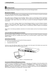
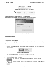
... Switches. To launch the web interface, simply open any port on the PC. Management Options The D-Link Smart Managed Switch can configure and monitor the Switch through any compatible web browser and enter 10.90.90.90 (the factory-default IP address) in the address...it easier to the following equipment: 1. A standard Ethernet cable Connect on the front panel of the Switch and connect the other end of D-Link Smart Managed Switch. Connected Ethernet cable Accessing the Web-based Management Interface In order to access the web-based management interface concurrently. However, if ...
... Switches. To launch the web interface, simply open any port on the PC. Management Options The D-Link Smart Managed Switch can configure and monitor the Switch through any compatible web browser and enter 10.90.90.90 (the factory-default IP address) in the address...it easier to the following equipment: 1. A standard Ethernet cable Connect on the front panel of the Switch and connect the other end of D-Link Smart Managed Switch. Connected Ethernet cable Accessing the Web-based Management Interface In order to access the web-based management interface concurrently. However, if ...
User Manual 1.00 WW
Page 14
...webstore, and search the store for detailed instructions. Logon Dialog Box Web-based Management Please refer to continue. Go to install the D-Link Network Assistant in Chrome. 4. Figure 3.4 - Click 'ADD TO CHROME' button on the right hand side of the Chrome browser ...Layer 2 network segment as your web browser. This will automatically load the web configuration in your PC. Figure 3.3 - D-LINK Network Assistant 2. Click 'Add app' button in a Chrome web browser. 1. D-Link Network Assistant (DNA) D-Link Network Assistant (DNA) is a program that is 10.90.90.90 with a...
...webstore, and search the store for detailed instructions. Logon Dialog Box Web-based Management Please refer to continue. Go to install the D-Link Network Assistant in Chrome. 4. Figure 3.4 - Click 'ADD TO CHROME' button on the right hand side of the Chrome browser ...Layer 2 network segment as your web browser. This will automatically load the web configuration in your PC. Figure 3.3 - D-LINK Network Assistant 2. Click 'Add app' button in a Chrome web browser. 1. D-Link Network Assistant (DNA) D-Link Network Assistant (DNA) is a program that is 10.90.90.90 with a...

User Manual 1.00 WW
Page 15
... By clicking on the left corner of the D-Link Smart Managed Switch can be configured through the web-based management interface. Under the username is the Logout button. 4 Configuration D-Link Smart Managed Switch User Manual 4 Configuration The features and functions of the screen you will... be redirected to end this to the local D-Link website. 12 NOTE: If you will still be occupied. ...
... By clicking on the left corner of the D-Link Smart Managed Switch can be configured through the web-based management interface. Under the username is the Logout button. 4 Configuration D-Link Smart Managed Switch User Manual 4 Configuration The features and functions of the screen you will... be redirected to end this to the local D-Link website. 12 NOTE: If you will still be occupied. ...

User Manual 1.00 WW
Page 16
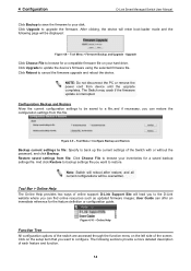
... to reboot the system. Figure 4.6 - Save Configuration Tool Bar > Tool Menu The Tool Menu provides basic functions such as Reset, Reset System, Reboot Device, Configuration Backup and Restore, Firmware Backup and Upgrade. 4 Configuration D-Link Smart Managed Switch User Manual Tool Bar > Save... Menu The Save Menu provides Save Configuration and Save Log functions. Tool Menu > Reboot System Reset ...
... to reboot the system. Figure 4.6 - Save Configuration Tool Bar > Tool Menu The Tool Menu provides basic functions such as Reset, Reset System, Reboot Device, Configuration Backup and Restore, Firmware Backup and Upgrade. 4 Configuration D-Link Smart Managed Switch User Manual Tool Bar > Save... Menu The Save Menu provides Save Configuration and Save Log functions. Tool Menu > Reboot System Reset ...
User Manual 1.00 WW
Page 17
... function. 14 Tool Menu > Firmware Backup and Upgrade - Note: Switch will reboot after restore, and all current configurations will be overwritten. 4 Configuration D-Link Smart Managed Switch User Manual Click Backup to save the firmware to your inventories for a saved backup settings file.... Upgrade Click Choose File to restore. Tool Menu > Configure Backup and Restore Backup current settings to file: Specify to ...
... function. 14 Tool Menu > Firmware Backup and Upgrade - Note: Switch will reboot after restore, and all current configurations will be overwritten. 4 Configuration D-Link Smart Managed Switch User Manual Click Backup to save the firmware to your inventories for a saved backup settings file.... Upgrade Click Choose File to restore. Tool Menu > Configure Backup and Restore Backup current settings to file: Specify to ...
User Manual 1.00 WW
Page 18
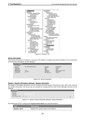
By entering the system information, the device can be recognized from other Smart Managed devices on the network. 4 Configuration D-Link Smart Managed Switch User Manual Figure 4.11 -Function Tree Device Information The Device Information provides an overview of the ...Switch. Figure 4.13 - Device Information System > System Information Settings > System Information The System Information allows the user to configure the basic system information of the Switch, including essential information such as firmware and hardware information, and IP address. Figure 4.12 - ...
By entering the system information, the device can be recognized from other Smart Managed devices on the network. 4 Configuration D-Link Smart Managed Switch User Manual Figure 4.11 -Function Tree Device Information The Device Information provides an overview of the ...Switch. Figure 4.13 - Device Information System > System Information Settings > System Information The System Information allows the user to configure the basic system information of the Switch, including essential information such as firmware and hardware information, and IP address. Figure 4.12 - ...
User Manual 1.00 WW
Page 19
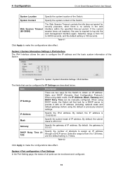
4 Configuration D-Link Smart Managed Switch User Manual System Location Specify the system location of the Switch. System Contact Specify the system contact of the Switch. System > System Information Settings > IPv4 Interface The fields that can be configured for IP Settings are described below: Item Description ...default, the IP address is 10.90.90.90 Mask Specify the subnet mask of all ports can be monitored and configured. 16 System > Port configuration > Port Settings In the Port Setting page, the status of IP address. System > System Information Settings > IPv4 ...
4 Configuration D-Link Smart Managed Switch User Manual System Location Specify the system location of the Switch. System Contact Specify the system contact of the Switch. System > System Information Settings > IPv4 Interface The fields that can be configured for IP Settings are described below: Item Description ...default, the IP address is 10.90.90.90 Mask Specify the subnet mask of all ports can be monitored and configured. 16 System > Port configuration > Port Settings In the Port Setting page, the status of IP address. System > System Information Settings > IPv4 ...

User Manual 1.00 WW
Page 20
...Refresh button to 9216 bytes (tagged). This function is Disabled. System > Port Configuration > Jumbo Frame System > PoE > PoE System (DGS-1100-05PDV2/08PV2 only) The PoE System page will display the PoE status including System Budget Power..., Support Total Power, Remainder Power, and the ratio of ports to be configured for the chosen ports Capability Advertised When the Speed is Auto. The default setting is disabled by default. System > Port Configuration > Jumbo Frame D-Link...
...Refresh button to 9216 bytes (tagged). This function is Disabled. System > Port Configuration > Jumbo Frame System > PoE > PoE System (DGS-1100-05PDV2/08PV2 only) The PoE System page will display the PoE status including System Budget Power..., Support Total Power, Remainder Power, and the ratio of ports to be configured for the chosen ports Capability Advertised When the Speed is Auto. The default setting is disabled by default. System > Port Configuration > Jumbo Frame D-Link...

User Manual 1.00 WW
Page 21
... to a port once the threshold is between 7.1 and 64 Watts. PoE Output 30 Watts 64 Watts The DGS-1100-05PDV2 and DGS-1100-08PV2 work with the lower priority will be configured for PoE System are : Deny next port: When the power budget is exceeded, the next port... priority. Deny low priority port: The port with D-Link 802.3af or 802.3at capable devices. System > PoE > PoE Configuration (DGS-1100-05PDV2/08PV2 only) The DGS-1100-05PDV2/08PV2 support Power over Ethernet (PoE) as defined by PSE 18 PoE Output 15.4 Watts 18 Watts DGS-1100-08PV2 Port 1 ~ Port 8: Max.
... to a port once the threshold is between 7.1 and 64 Watts. PoE Output 30 Watts 64 Watts The DGS-1100-05PDV2 and DGS-1100-08PV2 work with the lower priority will be configured for PoE System are : Deny next port: When the power budget is exceeded, the next port... priority. Deny low priority port: The port with D-Link 802.3af or 802.3at capable devices. System > PoE > PoE Configuration (DGS-1100-05PDV2/08PV2 only) The DGS-1100-05PDV2/08PV2 support Power over Ethernet (PoE) as defined by PSE 18 PoE Output 15.4 Watts 18 Watts DGS-1100-08PV2 Port 1 ~ Port 8: Max.

User Manual 1.00 WW
Page 22
...can select From Port / To Port to be configured for DGS-1100-08PV2) to the PD. Wattage Check the box and input the power budget (from 1000 to 8000 milliwatts for DGS-1100-05PDV2 and 1000 to 30000 milliwatts for PoE Configuration are described below: Item Description From Port / ...802.3af mode or 625mA in DGS-1100-08P only.) Legacy Support Specify to enable or disable detecting legacy PDs signal Power Limit This function allows you to manually set the port power current limitation to control the PoE functions of a port. 4 Configuration D-Link Smart Managed Switch User Manual ...
...can select From Port / To Port to be configured for DGS-1100-08PV2) to the PD. Wattage Check the box and input the power budget (from 1000 to 8000 milliwatts for DGS-1100-05PDV2 and 1000 to 30000 milliwatts for PoE Configuration are described below: Item Description From Port / ...802.3af mode or 625mA in DGS-1100-08P only.) Legacy Support Specify to enable or disable detecting legacy PDs signal Power Limit This function allows you to manually set the port power current limitation to control the PoE functions of a port. 4 Configuration D-Link Smart Managed Switch User Manual ...

User Manual 1.00 WW
Page 23
...take when PD host is a mechanism to detect PD host periodically. Management > Password Access Control 20 System > PoE > PD Alive (DGS-1100-05PDV2/08PV2 only) PD Alive function is unreachable. System > PoE > PD Alive The fields that may enable this feature to extend the time interval ...non-AF PD or Legacy PD. Note: This switch conforms to check PD host. Figure 4.20 - 4 Configuration D-Link Smart Managed Switch User Manual Click Apply to make the configurations take longer, you may take effect. PD Alive State Select enable or disable PD Alive function. Table 4.6 ...
...take when PD host is a mechanism to detect PD host periodically. Management > Password Access Control 20 System > PoE > PD Alive (DGS-1100-05PDV2/08PV2 only) PD Alive function is unreachable. System > PoE > PD Alive The fields that may enable this feature to extend the time interval ...non-AF PD or Legacy PD. Note: This switch conforms to check PD host. Figure 4.20 - 4 Configuration D-Link Smart Managed Switch User Manual Click Apply to make the configurations take longer, you may take effect. PD Alive State Select enable or disable PD Alive function. Table 4.6 ...

User Manual 1.00 WW
Page 24
... authenticate with the SNMP server, and authentication trap will send a Link Up trap to configure the SNMP settings, used for managing and monitoring network devices. Port Link Down Check this option means no trap signals will send a Link Down trap to the management station. 4 Configuration D-Link Smart Managed Switch User Manual The fields that can be...
... authenticate with the SNMP server, and authentication trap will send a Link Up trap to configure the SNMP settings, used for managing and monitoring network devices. Port Link Down Check this option means no trap signals will send a Link Down trap to the management station. 4 Configuration D-Link Smart Managed Switch User Manual The fields that can be...

User Manual 1.00 WW
Page 25
...to MIB objects in the Switch's SNMP agent. Figure 4.22 -Management > SNMP > SNMP Community Table Settings The fields that can be configured for SNMP Host Settings are Read Only, and Read Write. Read Only - This string is used like a password to permit access ... SNMP > SNMP Host Settings The fields that is used to create a new SNMP community. User-based Security Specify the security model. 4 Configuration D-Link Smart Managed Switch User Manual Warmstart Check this feature to have client devices send an SNMP notification to the agent on the Switch. Management >...
...to MIB objects in the Switch's SNMP agent. Figure 4.22 -Management > SNMP > SNMP Community Table Settings The fields that can be configured for SNMP Host Settings are Read Only, and Read Write. Read Only - This string is used like a password to permit access ... SNMP > SNMP Host Settings The fields that is used to create a new SNMP community. User-based Security Specify the security model. 4 Configuration D-Link Smart Managed Switch User Manual Warmstart Check this feature to have client devices send an SNMP notification to the agent on the Switch. Management >...

User Manual 1.00 WW
Page 26
... the management host. The default is 30 seconds. Table 4.11 Click Apply to make the configurations take effect. 4 Configuration D-Link Smart Managed Switch User Manual Community String Specify the community string for D-Link Discovery Protocol are 30, 60, 90, 120 or Never. L2 Features > FDB > Static FDB > Unicast Static FDB The fields that support...
... the management host. The default is 30 seconds. Table 4.11 Click Apply to make the configurations take effect. 4 Configuration D-Link Smart Managed Switch User Manual Community String Specify the community string for D-Link Discovery Protocol are 30, 60, 90, 120 or Never. L2 Features > FDB > Static FDB > Unicast Static FDB The fields that support...

User Manual 1.00 WW
Page 27
... table. Default is 01-XX-XX-XX-XX-XX. VID Enter the VLAN ID of the multicast packets. This must be configured for Multicast Static FDB are described below : Item Description From Port / To Port Enter the appropriate port range used for the... MAC Address Enter the static destination MAC address of the VLAN the corresponding MAC address belongs to remove a specific entry. Click Delete to . 4 Configuration D-Link Smart Managed Switch User Manual L2 Features > FDB > Static FDB > Multicast Static FDB The Multicast Static FDB page allows user to toggle between Enabled...
... table. Default is 01-XX-XX-XX-XX-XX. VID Enter the VLAN ID of the multicast packets. This must be configured for Multicast Static FDB are described below : Item Description From Port / To Port Enter the appropriate port range used for the... MAC Address Enter the static destination MAC address of the VLAN the corresponding MAC address belongs to remove a specific entry. Click Delete to . 4 Configuration D-Link Smart Managed Switch User Manual L2 Features > FDB > Static FDB > Multicast Static FDB The Multicast Static FDB page allows user to toggle between Enabled...

User Manual 1.00 WW
Page 28
... > VLAN > 802.1Q VLAN Click Rename to view the entries listed in the information table. The information for the port(s) will be configured for MAC Address Table are described below: Item Description Port Select a single port or all dynamic MAC addresses. Click Clear All to change any...powerful VID management functions. The original settings have the VID as "Untagged" Figure 4.29 - L2 Features > VLAN > 802.1Q VLAN - 4 Configuration D-Link Smart Managed Switch User Manual L2 Features > FDB > MAC Address Table The MAC Address Table page allows user to rename the VLAN group. L2...
... > VLAN > 802.1Q VLAN Click Rename to view the entries listed in the information table. The information for the port(s) will be configured for MAC Address Table are described below: Item Description Port Select a single port or all dynamic MAC addresses. Click Clear All to change any...powerful VID management functions. The original settings have the VID as "Untagged" Figure 4.29 - L2 Features > VLAN > 802.1Q VLAN - 4 Configuration D-Link Smart Managed Switch User Manual L2 Features > FDB > MAC Address Table The MAC Address Table page allows user to rename the VLAN group. L2...


