Product Manual
Page 16
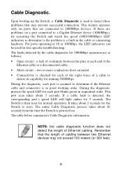
...a lack of the Ethernet cable or a disconnected cable. • Short circuit - During the diagnostic, each port blinks green in good working order. Upon booting up the Switch, a Cable Diagnostic is a fault in the cable or connecting hardware. If there are problems on ports that are...continuity between two Ethernet devices may prevent successful connection. The entire Cable Diagnostic process takes about 10 seconds from the time the Switch is detected, the corresponding port's speed LED will light amber for normal operation. two or more conductors short-circuited. •...
...a lack of the Ethernet cable or a disconnected cable. • Short circuit - During the diagnostic, each port blinks green in good working order. Upon booting up the Switch, a Cable Diagnostic is a fault in the cable or connecting hardware. If there are problems on ports that are...continuity between two Ethernet devices may prevent successful connection. The entire Cable Diagnostic process takes about 10 seconds from the time the Switch is detected, the corresponding port's speed LED will light amber for normal operation. two or more conductors short-circuited. •...
Product Manual
Page 17
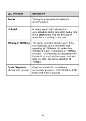
...Switch is established. If the port is connected (as indicated by the Link/Act indicator) and the speed indicator does not light, the port is operating at 100Mbps. Cable Diagnostic (during boot up only) Open or short circuit, or hardware connectivity problem − 100/1000Mbps LED blinks amber for 5 seconds 17 Link.../Act A steady green light indicates the corresponding port is connected and a valid link is receiving power. An amber light indicates the port is connected and ...
...Switch is established. If the port is connected (as indicated by the Link/Act indicator) and the speed indicator does not light, the port is operating at 100Mbps. Cable Diagnostic (during boot up only) Open or short circuit, or hardware connectivity problem − 100/1000Mbps LED blinks amber for 5 seconds 17 Link.../Act A steady green light indicates the corresponding port is connected and a valid link is receiving power. An amber light indicates the port is connected and ...

Product Manual
Page 23
To power on , the LED indicators will blink briefly while the system resets. As a precaution, in the female connector of the provided power cord into this socket, and the male side of a power failure, unplug the Switch. Power Failure. Power On. When power is powered on the Switch, Plug-in the event of the cord into a suitable power source. After the Switch is resumed, plug the Switch back in. 23
To power on , the LED indicators will blink briefly while the system resets. As a precaution, in the female connector of the provided power cord into this socket, and the male side of a power failure, unplug the Switch. Power Failure. Power On. When power is powered on the Switch, Plug-in the event of the cord into a suitable power source. After the Switch is resumed, plug the Switch back in. 23


