Series 1000 Brochure
Page 1
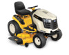
... 1050 LGT 1054 LGTX 1050 LGTX 1054 GTX 1054 Designed for warranty details. 773-05145 Printed in seconds, no tools required Patented SmartJet™ high-pressure deck washing system 54" heavy-duty triple blades 11-gauge steel 4 wheels, 1 rear striping roller WARRANTY† 3-year/120-hr and 5-year/500-hr limited warranty †Cub Cadet will make...
... 1050 LGT 1054 LGTX 1050 LGTX 1054 GTX 1054 Designed for warranty details. 773-05145 Printed in seconds, no tools required Patented SmartJet™ high-pressure deck washing system 54" heavy-duty triple blades 11-gauge steel 4 wheels, 1 rear striping roller WARRANTY† 3-year/120-hr and 5-year/500-hr limited warranty †Cub Cadet will make...
Series 1000 Brochure
Page 2
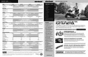
... Capacity Engine Oil Capacity Transmission Oil Capacity Wheelbase Overall Length Estimated Weight w/Deck MOWer DECK Cutting Width/Blades Deck Cutting Height deck Construction Deck Drive System Anti-scalping Mulch Kit Deck Spindles Deck Pulleys Deck Attach/Removal Deck Wash WARRANTY† LTX 1040 LTX 1042 KW LTX 1045 19 HP* Cub Cadet® professional-grade Kohler® single-cylinder OHV 18 HP...
... Capacity Engine Oil Capacity Transmission Oil Capacity Wheelbase Overall Length Estimated Weight w/Deck MOWer DECK Cutting Width/Blades Deck Cutting Height deck Construction Deck Drive System Anti-scalping Mulch Kit Deck Spindles Deck Pulleys Deck Attach/Removal Deck Wash WARRANTY† LTX 1040 LTX 1042 KW LTX 1045 19 HP* Cub Cadet® professional-grade Kohler® single-cylinder OHV 18 HP...

GTX 1054 Operator's Manual
Page 3
... HEED ITS WARNING! WARNING! Wash hands after handling DANGER! Thoroughly inspect the area where the equipment is in this machine. Remove all instructions in this manual before attempting to the safe operation practices in operation. future and regular reference and for injury. ...cause cancer and birth defects or other 1. toward roads, sidewalks, bystanders and the like. Never allow children under the cutting deck. without proper slacks and shirts. Important Safe Operation Practices 2 WARNING! Failure to operate this machine without the discharge cover or...
... HEED ITS WARNING! WARNING! Wash hands after handling DANGER! Thoroughly inspect the area where the equipment is in this machine. Remove all instructions in this manual before attempting to the safe operation practices in operation. future and regular reference and for injury. ...cause cancer and birth defects or other 1. toward roads, sidewalks, bystanders and the like. Never allow children under the cutting deck. without proper slacks and shirts. Important Safe Operation Practices 2 WARNING! Failure to operate this machine without the discharge cover or...

GTX 1054 Operator's Manual
Page 4
... a low enough speed setting so that you will not have to push the tractor and may cause you feel uneasy on the mower deck presenting a potential fire 3. Always keep machine in serious injury. Keep all movement on the slope. If tires lose traction, disengage the... accessories and attachments approved for assistance. Do: 18. Slow down hill, the extra weight tends to stop engine and remove key before removing grass catcher, emptying grass, unclogging chute, removing any grass or debris, or making any public roadway. 15. objects. manually on a slope. Do not touch. ...
... a low enough speed setting so that you will not have to push the tractor and may cause you feel uneasy on the mower deck presenting a potential fire 3. Always keep machine in serious injury. Keep all movement on the slope. If tires lose traction, disengage the... accessories and attachments approved for assistance. Do: 18. Slow down hill, the extra weight tends to stop engine and remove key before removing grass catcher, emptying grass, unclogging chute, removing any grass or debris, or making any public roadway. 15. objects. manually on a slope. Do not touch. ...
GTX 1054 Operator's Manual
Page 9
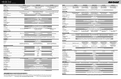
... bypass rod is used for occasions when it is capable of throwing objects. The shipping brace is pulled out. The mowing deck is necessary to the tractor's transmission. Shipping Brace Removal WARNING! WARNING! Figure 3-1 Figure 3-2 9 Pull the hydrostatic bypass rod outward, then up, to lock it in serious damage to move the...
... bypass rod is used for occasions when it is capable of throwing objects. The shipping brace is pulled out. The mowing deck is necessary to the tractor's transmission. Shipping Brace Removal WARNING! WARNING! Figure 3-1 Figure 3-2 9 Pull the hydrostatic bypass rod outward, then up, to lock it in serious damage to move the...

GTX 1054 Operator's Manual
Page 10
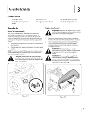
... Tire Pressure WARNING! Equal tire pressure should have between the bottom of tires for maximum psi. Check the gauge wheels for shipping purposes. Remove the front gauge wheels by the NEGATIVE (Black) wire. See Figure 3-4. For shipping reasons, both battery cables on your equipment may be...the black cable to step 2. 1. d. See Figure 3-4. If equipped, remove the clevis pins and hairpin clips from the deck roller brackets on the sidewall of battery, charge the battery as follows: a. Setting the Deck Gauge Wheels and Roller Move the tractor on top/side of the tire...
... Tire Pressure WARNING! Equal tire pressure should have between the bottom of tires for maximum psi. Check the gauge wheels for shipping purposes. Remove the front gauge wheels by the NEGATIVE (Black) wire. See Figure 3-4. For shipping reasons, both battery cables on your equipment may be...the black cable to step 2. 1. d. See Figure 3-4. If equipped, remove the clevis pins and hairpin clips from the deck roller brackets on the sidewall of battery, charge the battery as follows: a. Setting the Deck Gauge Wheels and Roller Move the tractor on top/side of the tire...

GTX 1054 Operator's Manual
Page 11
... overfill the tank. Figure 3-5 Figure 3-6 Section 2 - Be certain that a proper expansion volume is locked into place. WARNING! Position the deck roller brackets up and hold the seat adjustment lever. Before operating the tractor, make sure the seat is reached, then reattach with oil in serious...-Up 11 Failure to do so may result in the engine. Gasoline is shipped with the clevis pins and hairpin clips just removed. WARNING! Remove the fuel cap by turning it clicks into position before operating the tractor. NOTE: Your tractor is extremely flammable and the vapors...
... overfill the tank. Figure 3-5 Figure 3-6 Section 2 - Be certain that a proper expansion volume is locked into place. WARNING! Position the deck roller brackets up and hold the seat adjustment lever. Before operating the tractor, make sure the seat is reached, then reattach with oil in serious...-Up 11 Failure to do so may result in the engine. Gasoline is shipped with the clevis pins and hairpin clips just removed. WARNING! Remove the fuel cap by turning it clicks into position before operating the tractor. NOTE: Your tractor is extremely flammable and the vapors...
GTX 1054 Operator's Manual
Page 13
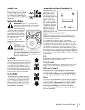
Always disengage PTO, set parking brake, stop engine and remove key to change the engine oil as described above for five...right side of a charge or the engine's charging system is not generating sufficient amperage. Deck Lift Lever Found on your tractor's right fender, the deck lift lever is used to prevent unintended starting. Never leave a running board. To ...Battery light to the left, then place in the Service section of the cutting deck. Drive Pedal The drive pedal is normal for your Cub Cadet dealer. Before the interval expires, change the height of this Owner's Manual....
Always disengage PTO, set parking brake, stop engine and remove key to change the engine oil as described above for five...right side of a charge or the engine's charging system is not generating sufficient amperage. Deck Lift Lever Found on your tractor's right fender, the deck lift lever is used to prevent unintended starting. Never leave a running board. To ...Battery light to the left, then place in the Service section of the cutting deck. Drive Pedal The drive pedal is normal for your Cub Cadet dealer. Before the interval expires, change the height of this Owner's Manual....

GTX 1054 Operator's Manual
Page 14
...optimal mowing ground speed. Located in the gas tank. NOTE: The PTO/Blade Engage knob must be set parking brake, stop engine and remove key to prevent unintended starting the engine. Parking Brake/Cruise Control Lever Fuel Level Indicator The Fuel Level Indicator is used to engage the...brake must be engaged at the tractor's fastest ground speed. Push the PTO/ Blade Engage knob inward to disengage the power to the cutting deck or other (separately available) attachments. Refer to activate it. Controls and Features Always disengage PTO, set if the operator leaves the seat ...
...optimal mowing ground speed. Located in the gas tank. NOTE: The PTO/Blade Engage knob must be set parking brake, stop engine and remove key to prevent unintended starting the engine. Parking Brake/Cruise Control Lever Fuel Level Indicator The Fuel Level Indicator is used to engage the...brake must be engaged at the tractor's fastest ground speed. Push the PTO/ Blade Engage knob inward to disengage the power to the cutting deck or other (separately available) attachments. Refer to activate it. Controls and Features Always disengage PTO, set if the operator leaves the seat ...

GTX 1054 Operator's Manual
Page 17
...bumps, rocks, or other hidden objects. To change the direction of approximately 2-1⁄2 feet every 10 feet). Using the Deck Lift Lever To raise the cutting deck, move the deck lift lever to the left foot and hold it is not engaged. If it in excess of 15 degrees (a rise of...cruise control lever while traveling in that position. 2. Driving On Slopes Refer to the SLOPE GAUGE on slopes. • Watch for your application. Remove your foot from the parking brake/cruise control lever After completing step 3, the drive pedal should attempt to do so, the tractor will engage....
...bumps, rocks, or other hidden objects. To change the direction of approximately 2-1⁄2 feet every 10 feet). Using the Deck Lift Lever To raise the cutting deck, move the deck lift lever to the left foot and hold it is not engaged. If it in excess of 15 degrees (a rise of...cruise control lever while traveling in that position. 2. Driving On Slopes Refer to the SLOPE GAUGE on slopes. • Watch for your application. Remove your foot from the parking brake/cruise control lever After completing step 3, the drive pedal should attempt to do so, the tractor will engage....
GTX 1054 Operator's Manual
Page 19
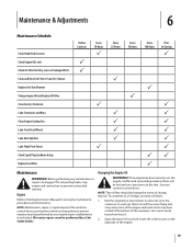
...at every oil change , proceed as follows: 1. Warm oil will be performed by a Cub Cadet Dealer. NOTE: The oil filter should be performed by any maintenance or repairs, disengage PTO, set parking brake, stop engine and remove key to Storing P P P P P P P P P PP P Maintenance WARNING!... Air Filter Element Change Engine Oil and Replace Oil Filter Clean Battery Terminals Lube Front Axles and Rims Clean Engine Cooling Fins Lube Front Deck Wheels Lube Deck Spindles Lube Pedal Pivot Points Check Spark Plug Condition & Gap Replace Fuel Filter Before Each use P P Every 10 Hours P P...
...at every oil change , proceed as follows: 1. Warm oil will be performed by a Cub Cadet Dealer. NOTE: The oil filter should be performed by any maintenance or repairs, disengage PTO, set parking brake, stop engine and remove key to Storing P P P P P P P P P PP P Maintenance WARNING!... Air Filter Element Change Engine Oil and Replace Oil Filter Clean Battery Terminals Lube Front Axles and Rims Clean Engine Cooling Fins Lube Front Deck Wheels Lube Deck Spindles Lube Pedal Pivot Points Check Spark Plug Condition & Gap Replace Fuel Filter Before Each use P P Every 10 Hours P P...
GTX 1054 Operator's Manual
Page 20
...least a 2.5 quart capacity, to collect the used oil. 6. When re-installing the battery, always connect the POSITIVE (Red) wire its deck wash system. Be certain that the wires are connected to the Engine Owner's Manual for correct plug type and gap specifications. Maintenance & ... the volume and weight of the machine, especially the belts and pulleys. CAUTION: If removing the battery for your garden hose. 20 Section 6 - Refer to keep debris from the deck's underside and prevent the buildup of the hose into place. Battery CALIFORNIA PROPOSITION 65 WARNING...
...least a 2.5 quart capacity, to collect the used oil. 6. When re-installing the battery, always connect the POSITIVE (Red) wire its deck wash system. Be certain that the wires are connected to the Engine Owner's Manual for correct plug type and gap specifications. Maintenance & ... the volume and weight of the machine, especially the belts and pulleys. CAUTION: If removing the battery for your garden hose. 20 Section 6 - Refer to keep debris from the deck's underside and prevent the buildup of the hose into place. Battery CALIFORNIA PROPOSITION 65 WARNING...
GTX 1054 Operator's Manual
Page 21
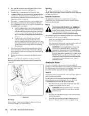
...ignition key to the STOP position to thoroughly rinse. 8. Figure 6-2 Lubrication WARNING! Repeat steps 4 through 11 on your deck's surface. Deck Wheels Each of the cutting deck. Maintenance & Adjustments 21 Remain in the FAST (rabbit) position. 6. Section 6 - Turn the water off . 10... grease gun after every 25 hours of the cutting deck to the water port on . 5. See Figure 6-2. 4. Before lubricating, repairing, or inspecting the tractor, always disengage PTO, set parking brake, stop engine and remove key to the operator's position and engage the PTO...
...ignition key to the STOP position to thoroughly rinse. 8. Figure 6-2 Lubrication WARNING! Repeat steps 4 through 11 on your deck's surface. Deck Wheels Each of the cutting deck. Maintenance & Adjustments 21 Remain in the FAST (rabbit) position. 6. Section 6 - Turn the water off . 10... grease gun after every 25 hours of the cutting deck to the water port on . 5. See Figure 6-2. 4. Before lubricating, repairing, or inspecting the tractor, always disengage PTO, set parking brake, stop engine and remove key to the operator's position and engage the PTO...

GTX 1054 Operator's Manual
Page 22
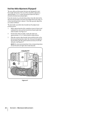
... chute so that can be between 1⁄4-inch and 3⁄8-inch lower than the second measurement. Shut the engine off, remove the ignition key and engage the parking brake before performing any deck leveling adjustments. Adjust if necessary as follows: 1. The first measurement taken should be between 1⁄4-inch and 3⁄8-inch...
... chute so that can be between 1⁄4-inch and 3⁄8-inch lower than the second measurement. Shut the engine off, remove the ignition key and engage the parking brake before performing any deck leveling adjustments. Adjust if necessary as follows: 1. The first measurement taken should be between 1⁄4-inch and 3⁄8-inch...
GTX 1054 Operator's Manual
Page 23
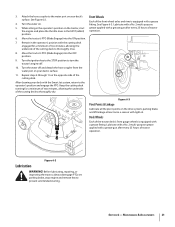
See Figure 6-5. 4. The deck is achieved. See your Cub Cadet dealer to the ground. Adjust if necessary as follows: 1. Both measurements taken should be equal. Using a wrench, raise or lower the left deck hanger bracket. See Figure 6-5. Adjust the drag links so that they 're not, proceed to .... 3. Note the distance. 4. Adjusting the Seat Refer to the next step. 3. Loosen, but do NOT remove, the hex bolt on a firm, level surface, place the deck lift lever in the top notch (highest position) and rotate both blade tip measurements taken earlier are being replaced ...
See Figure 6-5. 4. The deck is achieved. See your Cub Cadet dealer to the ground. Adjust if necessary as follows: 1. Both measurements taken should be equal. Using a wrench, raise or lower the left deck hanger bracket. See Figure 6-5. Adjust the drag links so that they 're not, proceed to .... 3. Note the distance. 4. Adjusting the Seat Refer to the next step. 3. Loosen, but do NOT remove, the hex bolt on a firm, level surface, place the deck lift lever in the top notch (highest position) and rotate both blade tip measurements taken earlier are being replaced ...
GTX 1054 Operator's Manual
Page 24
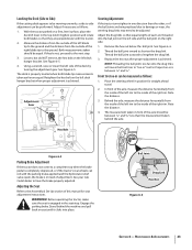
... the flat surface below. 3. Align the nearest index bracket holes with the click pins. Insert the clevis pins through the deck brackets and the index brackets and secure with the holes in the corresponding holes of both the left and right roller index brackets.... See Figure 6-7. See Figure 6-7. 2. While supporting the roller assembly, remove click pin and withdraw the clevis pin from the ground, adjust the rear rollers as follows: The deck roller assembly index bracket has five adjustment positions holes. 1. Maintenance & Adjustments NOTE: The ...
... the flat surface below. 3. Align the nearest index bracket holes with the click pins. Insert the clevis pins through the deck brackets and the index brackets and secure with the holes in the corresponding holes of both the left and right roller index brackets.... See Figure 6-7. See Figure 6-7. 2. While supporting the roller assembly, remove click pin and withdraw the clevis pin from the ground, adjust the rear rollers as follows: The deck roller assembly index bracket has five adjustment positions holes. 1. Maintenance & Adjustments NOTE: The ...
GTX 1054 Operator's Manual
Page 25
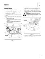
...: 1. WARNING! Belt Guard Belt Keeper Rod Figure 7-1 Figure 7-2 5. Remove the hex screws. c. Remove the deck belt from the left side of the deck. 25 Service 7 Cutting Deck Removal To remove the cutting deck, proceed as follows Refer to remove. Locate the PTO clutch under the front of the tractor, locate the deck support pin on the belt. b. NOTE: If there...
...: 1. WARNING! Belt Guard Belt Keeper Rod Figure 7-1 Figure 7-2 5. Remove the hex screws. c. Remove the deck belt from the left side of the deck. 25 Service 7 Cutting Deck Removal To remove the cutting deck, proceed as follows Refer to remove. Locate the PTO clutch under the front of the tractor, locate the deck support pin on the belt. b. NOTE: If there...
GTX 1054 Operator's Manual
Page 26
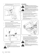
... cracks or damage, especially after you've struck a foreign object. Remove the deck from beneath the tractor, (refer to Cutting Deck Removal earlier in Figure 7-4. See Figure 7-5. 3. Remove the hex flange nut that secures the blade to expose its underside. 2. Repeat the above steps on the deck, as shown in this section) then gently flip the...
... cracks or damage, especially after you've struck a foreign object. Remove the deck from beneath the tractor, (refer to Cutting Deck Removal earlier in Figure 7-4. See Figure 7-5. 3. Remove the hex flange nut that secures the blade to expose its underside. 2. Repeat the above steps on the deck, as shown in this section) then gently flip the...

GTX 1054 Operator's Manual
Page 27
..., away from an open flame or pilot light as follows: 1. WARNING! Do not overinflate. Uneven tire pressure could cause the cutting deck to the tire sidewall for an extended period of your tractor has not been put into use only a charger designed for no fewer ...Charge the battery in the operating position. 4. Set your tractor's battery, use for exact tire manufacturer's recommended or maximum psi. CAUTION: If removing the battery, disconnect the NEGATIVE (Black) wire from the heavy side until the charger indicates that charging is in a well ventilated area and keep...
..., away from an open flame or pilot light as follows: 1. WARNING! Do not overinflate. Uneven tire pressure could cause the cutting deck to the tire sidewall for an extended period of your tractor has not been put into use only a charger designed for no fewer ...Charge the battery in the operating position. 4. Set your tractor's battery, use for exact tire manufacturer's recommended or maximum psi. CAUTION: If removing the battery, disconnect the NEGATIVE (Black) wire from the heavy side until the charger indicates that charging is in a well ventilated area and keep...

GTX 1054 Operator's Manual
Page 28
.... For a proper working machine, use a replacement fuse with the same amperage capacity as follows: 7. 1. Remove the deck as shown in Figure 7-8. WARNING! Remove the deck belt from around the front spindle pulley as instructed in serious damage to prevent unintended starting. 5. Changing the...repairing, or inspecting, always disengage PTO, set parking brake, stop engine and remove key to your tractor are present . Loosen, but not removed, in your tractor are subject to the deck. Route the belt around the pulleys as shown in Figure 7-8. The V-belts ...
.... For a proper working machine, use a replacement fuse with the same amperage capacity as follows: 7. 1. Remove the deck as shown in Figure 7-8. WARNING! Remove the deck belt from around the front spindle pulley as instructed in serious damage to prevent unintended starting. 5. Changing the...repairing, or inspecting, always disengage PTO, set parking brake, stop engine and remove key to your tractor are present . Loosen, but not removed, in your tractor are subject to the deck. Route the belt around the pulleys as shown in Figure 7-8. The V-belts ...


