

Operation Manual
Page 1
Visit the Craftsman web page: www.sears.com/craftsman Operator's Manual OM-194 199E April 2001 210 AMP MIG WELDER Model No. 117.205710 CAUTION: Before using welder, read this manual and follow all its Safety Rules and Operating Instructions. w Safety Rules w Installation w Operation w Maintenance w Parts w Español Sears, Roebuck and Co., Hoffman Estates, IL 60179 U.S.A.
Visit the Craftsman web page: www.sears.com/craftsman Operator's Manual OM-194 199E April 2001 210 AMP MIG WELDER Model No. 117.205710 CAUTION: Before using welder, read this manual and follow all its Safety Rules and Operating Instructions. w Safety Rules w Installation w Operation w Maintenance w Parts w Español Sears, Roebuck and Co., Hoffman Estates, IL 60179 U.S.A.
Operation Manual
Page 2
... and retain with your personal records. Warranty On Welding Gun or Cables, Welder, and Welder's Transformer Effective January 1, 2000 Full One Year Warranty for Craftsman Welding Gun or Cables. Full Three Year Warranty on Craftsman Welder. For one year from state to a defect in normal operation, such... as contact tips, nozzles, gun liners, and drive rolls. WARRANTY SERVICE IS AVAILABLE BY SIMPLY CONTACTING THE NEAREST SEARS SERVICE CENTER. This warranty does not cover parts consumed in ...
... and retain with your personal records. Warranty On Welding Gun or Cables, Welder, and Welder's Transformer Effective January 1, 2000 Full One Year Warranty for Craftsman Welding Gun or Cables. Full Three Year Warranty on Craftsman Welder. For one year from state to a defect in normal operation, such... as contact tips, nozzles, gun liners, and drive rolls. WARRANTY SERVICE IS AVAILABLE BY SIMPLY CONTACTING THE NEAREST SEARS SERVICE CENTER. This warranty does not cover parts consumed in ...
Operation Manual
Page 3
...Clamp 7 2-6. Front Panel Controls 14 SECTION 4 - Replacing Switch And/Or Head Tube 17 4-6. Troubleshooting - Common MIG Shielding Gases 28 SECTION 7 - Volt-Ampere Curves 5 2-3. Excessive Spatter 25 6-9. Arc Welding Hazards 1 1-3. Additional Symbols for welding or cutting, produces fumes... Tip 18 4-7. The following terms are used interchangeably throughout this manual: MIG = GMAW WARNING This product, when used for Installation, Operation, and Maintenance 3 1-4. MIG WELDING (GMAW) GUIDELINES 20 6-1. Troubleshooting - PARTS LIST 29 Español 35 OM-194 199
...Clamp 7 2-6. Front Panel Controls 14 SECTION 4 - Replacing Switch And/Or Head Tube 17 4-6. Troubleshooting - Common MIG Shielding Gases 28 SECTION 7 - Volt-Ampere Curves 5 2-3. Excessive Spatter 25 6-9. Arc Welding Hazards 1 1-3. Additional Symbols for welding or cutting, produces fumes... Tip 18 4-7. The following terms are used interchangeably throughout this manual: MIG = GMAW WARNING This product, when used for Installation, Operation, and Maintenance 3 1-4. MIG WELDING (GMAW) GUIDELINES 20 6-1. Troubleshooting - PARTS LIST 29 Español 35 OM-194 199
Operation Manual
Page 4
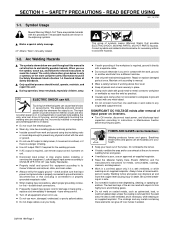
...-free insulating gloves and body protection. D Do not use exhaust at once. D Turn off toxic fumes if welded. Repair or replace damaged parts at the arc to manual. Maintain unit according to remove welding fumes and gases. D Clamp work , ground, or another electrode from the ... BEFORE USING som _nd_4/98 1-1. Watch Out! D Do not touch live . The coatings and any metal object. There are electrically live electrical parts. Y Only qualified persons should install, operate, maintain, and repair this manual to call attention to its Owner's Manual and national, state, and...
...-free insulating gloves and body protection. D Do not use exhaust at once. D Turn off toxic fumes if welded. Repair or replace damaged parts at the arc to manual. Maintain unit according to remove welding fumes and gases. D Clamp work , ground, or another electrode from the ... BEFORE USING som _nd_4/98 1-1. Watch Out! D Do not touch live . The coatings and any metal object. There are electrically live electrical parts. Y Only qualified persons should install, operate, maintain, and repair this manual to call attention to its Owner's Manual and national, state, and...
Operation Manual
Page 5
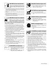
...protection if noise level is not possible, tightly cover them to treat them and associated parts in use approved air-supplied respirator. Since gas cylinders are properly prepared according to the ...filter to prevent falling or tipping. As welds cool, they are normally part of the welding arc. D Do not touch hot parts bare handed. D Allow cooling period before going near arc welding, ...arcs. Shielding gas cylinders contain gas under your welding helmet. D Do not use . HOT PARTS can burn eyes and skin. ARC RAYS can cause severe burns. warn others not to thaw...
...protection if noise level is not possible, tightly cover them to treat them and associated parts in use approved air-supplied respirator. Since gas cylinders are properly prepared according to the ...filter to prevent falling or tipping. As welds cool, they are normally part of the welding arc. D Do not touch hot parts bare handed. D Allow cooling period before going near arc welding, ...arcs. Shielding gas cylinders contain gas under your welding helmet. D Do not use . HOT PARTS can burn eyes and skin. ARC RAYS can cause severe burns. warn others not to thaw...

Operation Manual
Page 6
...Gas Association, 1235 Jefferson Davis Highway, Suite 501, Arlington, VA 22202. Cutting And Welding Processes, NFPA Standard 51B, from moving parts such as drive rolls. D Do not block or filter airflow to this installation. D Have only qualified persons familiar with radio ...possible interference, keep spark gaps at once. 1-3. D Do not install or place unit on grounded wrist strap BEFORE handling boards or parts. MOVING PARTS can cause interference. H.F. ARC WELDING can cause injury. D Be sure this welding machine is responsible for Safety in Cylinders, CGA Pamphlet...
...Gas Association, 1235 Jefferson Davis Highway, Suite 501, Arlington, VA 22202. Cutting And Welding Processes, NFPA Standard 51B, from moving parts such as drive rolls. D Do not block or filter airflow to this installation. D Have only qualified persons familiar with radio ...possible interference, keep spark gaps at once. 1-3. D Do not install or place unit on grounded wrist strap BEFORE handling boards or parts. MOVING PARTS can cause interference. H.F. ARC WELDING can cause injury. D Be sure this welding machine is responsible for Safety in Cylinders, CGA Pamphlet...
Operation Manual
Page 21
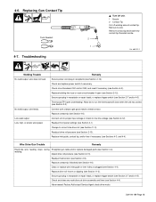
... tip, and/or liner if necessary (see Section 4-6). Wire Drive/Gun Trouble Remedy Electrode wire feeding stops during Straighten gun cable and/or replace damaged parts (see Section 2-9). welding. Readjust hub tension (see Section 4-4). Clean or replace wire inlet guide or liner if dirty or plugged (see Section 11-3). Replace drive...
... tip, and/or liner if necessary (see Section 4-6). Wire Drive/Gun Trouble Remedy Electrode wire feeding stops during Straighten gun cable and/or replace damaged parts (see Section 2-9). welding. Readjust hub tension (see Section 4-4). Clean or replace wire inlet guide or liner if dirty or plugged (see Section 11-3). Replace drive...

Operation Manual
Page 23
Disconnect both battery cables before welding on a vehicle. Place work clamp as close to the weld as possible. SECTION 6 - Typical MIG Process Connections Regulator/ Flowmeter Y Weld current can damage electronic parts in vehicles. Shielding Gas Wire Feeder/ Gas Power Source Gun Work Clamp Workpiece light mig 5/967 / Ref. 801 909 / 801 570-B OM-194 199 Page 20 MIG WELDING (GMAW) GUIDELINES 6-1.
Disconnect both battery cables before welding on a vehicle. Place work clamp as close to the weld as possible. SECTION 6 - Typical MIG Process Connections Regulator/ Flowmeter Y Weld current can damage electronic parts in vehicles. Shielding Gas Wire Feeder/ Gas Power Source Gun Work Clamp Workpiece light mig 5/967 / Ref. 801 909 / 801 570-B OM-194 199 Page 20 MIG WELDING (GMAW) GUIDELINES 6-1.
Operation Manual
Page 32
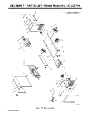
may be purchased locally. 11 12 13 14 15 16 17 18 19 20 21 10 9 8 7 6 + - 5 38 22 4 (Fig.7-2) 23 25 26 27 39 24 37 3 43 32 33 42 31 30 41 29 40 28 36 12 35 34 9 OM-194 199 Page 29 Figure 7-1. SECTION 7 - PARTS LIST-Welder Model No. 117.205710 . * Standard hardware item - Main Assembly 801 572-C
may be purchased locally. 11 12 13 14 15 16 17 18 19 20 21 10 9 8 7 6 + - 5 38 22 4 (Fig.7-2) 23 25 26 27 39 24 37 3 43 32 33 42 31 30 41 29 40 28 36 12 35 34 9 OM-194 199 Page 29 Figure 7-1. SECTION 7 - PARTS LIST-Welder Model No. 117.205710 . * Standard hardware item - Main Assembly 801 572-C
Operation Manual
Page 33
... 1 . . . 2 134 464 . . BRACKET, bottle retainer 1 . . . 11 602 387 . . WHEEL, rubolene 10in dia x 2.25 2 . . . 19 602 250 . . RING, rtng ext .750 shaft 2 . . . 21 Z . . . . **180 989 . . OM-194 199 Page 30 Parts List-Welder Model No. 117.205710 Item Dia. HANDLE 1 . . . 35 130 750 . . CENTER BAFFLE, w/components 1 . . . 5 . . . . THERMOSTAT, NC open 211F 1 . . . 6 . . . . . BRACKET RECTIFIER 1 191 375...
... 1 . . . 2 134 464 . . BRACKET, bottle retainer 1 . . . 11 602 387 . . WHEEL, rubolene 10in dia x 2.25 2 . . . 19 602 250 . . RING, rtng ext .750 shaft 2 . . . 21 Z . . . . **180 989 . . OM-194 199 Page 30 Parts List-Welder Model No. 117.205710 Item Dia. HANDLE 1 . . . 35 130 750 . . CENTER BAFFLE, w/components 1 . . . 5 . . . . THERMOSTAT, NC open 211F 1 . . . 6 . . . . . BRACKET RECTIFIER 1 191 375...
Operation Manual
Page 34
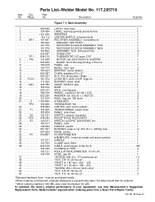
...436 . . BAFFLE, center 1 . . . 10 . . . . . BUSS BAR, negative 1 . . . 14 188 846 . . . . Part No. Mkgs. NUT, 625-11 .94 hex 1 . . . 3 605 941 . . SPRING, cprsn .84500 x .110W 1 . . . 5 057 971 . . WASHER, brake plastic 1 . . . 9 180 915 . . BUSS BAR, positive 1 . . . 13 191 102 . . . . C6 . . . . 191 385 . . SCREW, .010-32... 15 14 13 16 17 18 34 12 35 27 20 23 26 25 24 36 22 21 Figure 7-2. Description Figure 7-2. Parts List-Welder Model No. 117.205710 . * Standard hardware item - SPRING, cprsn 2.430 OD x .90 wire x 2.500 1 . ....
...436 . . BAFFLE, center 1 . . . 10 . . . . . BUSS BAR, negative 1 . . . 14 188 846 . . . . Part No. Mkgs. NUT, 625-11 .94 hex 1 . . . 3 605 941 . . SPRING, cprsn .84500 x .110W 1 . . . 5 057 971 . . WASHER, brake plastic 1 . . . 9 180 915 . . BUSS BAR, positive 1 . . . 13 191 102 . . . . C6 . . . . 191 385 . . SCREW, .010-32... 15 14 13 16 17 18 34 12 35 27 20 23 26 25 24 36 22 21 Figure 7-2. Description Figure 7-2. Parts List-Welder Model No. 117.205710 . * Standard hardware item - SPRING, cprsn 2.430 OD x .90 wire x 2.500 1 . ....
Operation Manual
Page 35
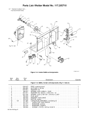
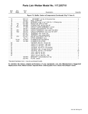
... switch 1 *Standard hardware item - Baffle, Center w/Components (Continued) (Fig 7-1 Item 4) . . . 15 083 147 . . . . GROMMET, scr No. 8/10 panel hole 4 . . . 16 180 927 . . CIRCUIT CARD ASSEMBLY, control 1 . . . 22 134 201 . . STAND-OFF SUPPORT, PC card 4 . . . 23 . . . . RELAY, encl 24VAC DPDT 20 1 . ....your equipment, use only Manufacturer's Suggested Replacement Parts. OM-194 199 Page 32 BRACKET, consumable/tool tray 1 202 449 . . Model number required when ordering parts from a Sears Parts/Repair Center. Parts List-Welder Model No. 117.205710 Item Dia. CR1...
... switch 1 *Standard hardware item - Baffle, Center w/Components (Continued) (Fig 7-1 Item 4) . . . 15 083 147 . . . . GROMMET, scr No. 8/10 panel hole 4 . . . 16 180 927 . . CIRCUIT CARD ASSEMBLY, control 1 . . . 22 134 201 . . STAND-OFF SUPPORT, PC card 4 . . . 23 . . . . RELAY, encl 24VAC DPDT 20 1 . ....your equipment, use only Manufacturer's Suggested Replacement Parts. OM-194 199 Page 32 BRACKET, consumable/tool tray 1 202 449 . . Model number required when ordering parts from a Sears Parts/Repair Center. Parts List-Welder Model No. 117.205710 Item Dia. CR1...
Operation Manual
Page 36
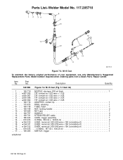
... . CORD, trigger assembly 1 . . . 14 . . . . . 079 974 . . O-RING, .187 ID x .103CS rbr 1 . . . 17 . . . . . 196 255 . . Parts List-Welder Model No. 117.205710 8 1 2 35 9 10 11 17 12 15 16 13 14 9 11 12 800 792-B Figure 7-3. No. LINER, monocoil .035/.045 wire x 15ft... . . 2 . . . ♦000 067 . . TIP, contact scr .035 wire x 1.125 . . . 2 . . . ♦000 069 . . STRAIN RELIEF, cable 2 . . . 13 . . . . . 180 433 . . NOZZLE, slip type .500 orf flush 1 . . . 2 . . . ♦087 299 . . M-15 Gun (Fig 7-1 Item 36) . . . 1 . . . . . 169 715 . . TIP, contact...
... . CORD, trigger assembly 1 . . . 14 . . . . . 079 974 . . O-RING, .187 ID x .103CS rbr 1 . . . 17 . . . . . 196 255 . . Parts List-Welder Model No. 117.205710 8 1 2 35 9 10 11 17 12 15 16 13 14 9 11 12 800 792-B Figure 7-3. No. LINER, monocoil .035/.045 wire x 15ft... . . 2 . . . ♦000 067 . . TIP, contact scr .035 wire x 1.125 . . . 2 . . . ♦000 069 . . STRAIN RELIEF, cable 2 . . . 13 . . . . . 180 433 . . NOZZLE, slip type .500 orf flush 1 . . . 2 . . . ♦087 299 . . M-15 Gun (Fig 7-1 Item 36) . . . 1 . . . . . 169 715 . . TIP, contact...

Operation Manual
Page 37
....315 x .866 x .27 (consisting of your equipment, use only Manufacturer's Suggested Replacement Parts. KNOB, T 2.000 bar w/.312-18 st 1 . . . 14 174 609 . . Model number required when ordering parts from a Sears Parts /Repair Center. Drive Assembly, Wire (Fig 7-2 Item 29) . . . 1 196 ....688 OD 1 . . . 22 WASHER, lock .168 ID x .277 OD 1 . . . 23 SCREW, .010-32 x .87 hexwhd 2 1 2 . Parts List-Welder Model No. 117.205710 Item Part No. MOTOR, gear 24VDC 1 . . . 2 180 929 . . HOUSING, motor drive 1 . . . 3 198 789 . . PIN, hinge 1 . . . 9 124 817 . . . . GUIDE, wire inlet...
....315 x .866 x .27 (consisting of your equipment, use only Manufacturer's Suggested Replacement Parts. KNOB, T 2.000 bar w/.312-18 st 1 . . . 14 174 609 . . Model number required when ordering parts from a Sears Parts /Repair Center. Drive Assembly, Wire (Fig 7-2 Item 29) . . . 1 196 ....688 OD 1 . . . 22 WASHER, lock .168 ID x .277 OD 1 . . . 23 SCREW, .010-32 x .87 hexwhd 2 1 2 . Parts List-Welder Model No. 117.205710 Item Part No. MOTOR, gear 24VDC 1 . . . 2 180 929 . . HOUSING, motor drive 1 . . . 3 198 789 . . PIN, hinge 1 . . . 9 124 817 . . . . GUIDE, wire inlet...


