
Operation Manual
Page 7
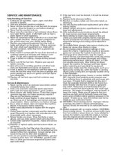
... than from the area of spillage and avoid creating any fuelsoaked debris. On multiple blade mowers, take care as required. 10. Keep body and hands awayfrom pin holes or nozzles ... Maintain or replace safety and instructions labels, as near the moving parts, such as a hydro pump cooling fan, when the tractor is hot as necessary. 16. Only authorized service locations should be... surgically removed within a few hours by an authorized technician. 26. If leaks occur, have...
... than from the area of spillage and avoid creating any fuelsoaked debris. On multiple blade mowers, take care as required. 10. Keep body and hands awayfrom pin holes or nozzles ... Maintain or replace safety and instructions labels, as near the moving parts, such as a hydro pump cooling fan, when the tractor is hot as necessary. 16. Only authorized service locations should be... surgically removed within a few hours by an authorized technician. 26. If leaks occur, have...
Operation Manual
Page 8
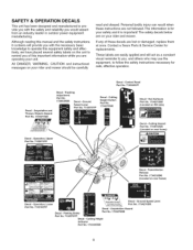
... operate this equipment safely and effectively, we have placed several safety labels on your unit. Amputation Hazard Part No. 1704276SM Decal - Contact a Sears Parts & Service Center for your rider and mower should be carefully read and obeyed. Operation, Lower Part No. 7103185YP ig '_,,Amputation Hazard '_, '_, Toav0idinj(iryfromr01aling "_ '_,, )a es, staycear 0 decke ge.!_, Decal - Cutting Hazard...
... operate this equipment safely and effectively, we have placed several safety labels on your unit. Amputation Hazard Part No. 1704276SM Decal - Contact a Sears Parts & Service Center for your rider and mower should be carefully read and obeyed. Operation, Lower Part No. 7103185YP ig '_,,Amputation Hazard '_, '_, Toav0idinj(iryfromr01aling "_ '_,, )a es, staycear 0 decke ge.!_, Decal - Cutting Hazard...

Operation Manual
Page 18
... and engine (see STARTING THE ENGINE). 2. Pull the ground speed control levers in STOPPING THE RIDER AND ENGINE. Turn off the mower blades by pushing the mower blade switch down follow the procedure given in to OFE Remove the key. Move the engine speed control to SLOW ... the engine (see STOPPING THE RIDER AND ENGINE). The rider can be pushed by hand. , After moving parts to stop rider movement. 2. Turn the mower blades ON (pull switch up). 5. When finished, turn the ignition switch OFF, remove the key, and wait for starting a cold engine. Transmission Release Levers 18 ...
... and engine (see STARTING THE ENGINE). 2. Pull the ground speed control levers in STOPPING THE RIDER AND ENGINE. Turn off the mower blades by pushing the mower blade switch down follow the procedure given in to OFE Remove the key. Move the engine speed control to SLOW ... the engine (see STOPPING THE RIDER AND ENGINE). The rider can be pushed by hand. , After moving parts to stop rider movement. 2. Turn the mower blades ON (pull switch up). 5. When finished, turn the ignition switch OFF, remove the key, and wait for starting a cold engine. Transmission Release Levers 18 ...
Operation Manual
Page 21
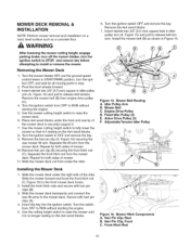
... the key. Insert ratchet into 3/8" (9.5 mm) square hole in START/PARK position, turn the ignition switch to STOP, and remove key before attempting to install or remove the mower. Turn the mower blades OFF, put the ground speed control levers in idler pulley arm (A, Figure 15)... ignition switch from under the right side of mower. 10. Use the mower cutting height switch to release belt tension. Mower Belt Routing A. Arbor Drive Pulley (3) F. Remove the 4x4 wood blocks. 7. Turn the ignition switch to stop. 2. Repeat for all moving parts to OFF and remove the key. 9. Secure...
... the key. Insert ratchet into 3/8" (9.5 mm) square hole in START/PARK position, turn the ignition switch to STOP, and remove key before attempting to install or remove the mower. Turn the mower blades OFF, put the ground speed control levers in idler pulley arm (A, Figure 15)... ignition switch from under the right side of mower. 10. Use the mower cutting height switch to release belt tension. Mower Belt Routing A. Arbor Drive Pulley (3) F. Remove the 4x4 wood blocks. 7. Turn the ignition switch to stop. 2. Repeat for all moving parts to OFF and remove the key. 9. Secure...
Operation Manual
Page 23
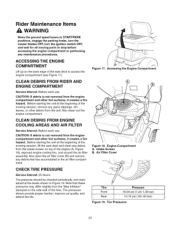
... Pressures 23 Rider Maintenance Items WARNING Move the ground speed levers to START/PARK positions, engage the parking brake, turn the mower blades OFF, turn the ignition switch OFF, and wait for all moving parts to access the engine compartment (see Figure 17). Also open the air filter cover (B) and remove any debris that...
... Pressures 23 Rider Maintenance Items WARNING Move the ground speed levers to START/PARK positions, engage the parking brake, turn the mower blades OFF, turn the ignition switch OFF, and wait for all moving parts to access the engine compartment (see Figure 17). Also open the air filter cover (B) and remove any debris that...

Operation Manual
Page 24
... \ \ Figure 21. Oil: • hydro linkage • brake linkage • frame pivot points • mower deck height adjustment linkage Generally, all greases are compatible. Lubricating Rider o Figure 20. Lubricating Rider Figure 23. Use automotive-type lithi- Remember to ...unit at the locations shown in Figures 20 through 23 as well as the following lubrication points. Lubricating Mower Lift 24 Not all moving metal parts should be oiled where contact is made with other parts. Keep oil and grease off belts and pulleys. LUBRICATION Service Interval: 25 hours. um grease. ...
... \ \ Figure 21. Oil: • hydro linkage • brake linkage • frame pivot points • mower deck height adjustment linkage Generally, all greases are compatible. Lubricating Rider o Figure 20. Lubricating Rider Figure 23. Use automotive-type lithi- Remember to ...unit at the locations shown in Figures 20 through 23 as well as the following lubrication points. Lubricating Mower Lift 24 Not all moving metal parts should be oiled where contact is made with other parts. Keep oil and grease off belts and pulleys. LUBRICATION Service Interval: 25 hours. um grease. ...
Operation Manual
Page 27
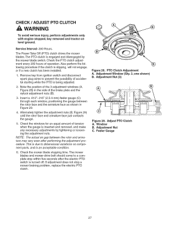
... belt should come to a complete stop a mower braking problem, replace the electric PTO clutch. Window B. Feeler Gauge 27 Service Interval: 200 Hours. The PTO clutch is turned off. This is due to prevent the possibility of tension when the gauge is an acceptable condition. 6. Adjustment... CLUTCH WARNING To avoid serious injury, perform adjustments only with engine stopped, key removed and tractor on component parts, and is inserted and removed, and make any necessary adjustments by the mower blade switch. Note the position of the 3 adjustment windows (A, Figure 28) in Figure ...
... belt should come to a complete stop a mower braking problem, replace the electric PTO clutch. Window B. Feeler Gauge 27 Service Interval: 200 Hours. The PTO clutch is turned off. This is due to prevent the possibility of tension when the gauge is an acceptable condition. 6. Adjustment... CLUTCH WARNING To avoid serious injury, perform adjustments only with engine stopped, key removed and tractor on component parts, and is inserted and removed, and make any necessary adjustments by the mower blade switch. Note the position of the 3 adjustment windows (A, Figure 28) in Figure ...
Operation Manual
Page 33
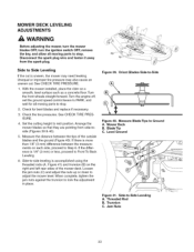
... jam nuts (C) and adjust the nuts up or down to mid position. Jam Nuts Leveling 33 MOWER DECK LEVELING ADJUSTMENTS WARNING Before adjusting the mower, turn the mower blades OFF, turn the ignition switch OFF, remove the key, and allow all moving parts to -side leveling is more than 1/8" (3 mm) difference between the tips of the...
... jam nuts (C) and adjust the nuts up or down to mid position. Jam Nuts Leveling 33 MOWER DECK LEVELING ADJUSTMENTS WARNING Before adjusting the mower, turn the mower blades OFF, turn the ignition switch OFF, remove the key, and allow all moving parts to -side leveling is more than 1/8" (3 mm) difference between the tips of the...
Operation Manual
Page 36
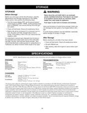
.... • Check all maintenance items. • Fill with fuel) in the essential fuel system parts such as a furnace, water heater, etc.) and cause an explosion. Fuel vapors can damage the... is removed, put in the Safety Rules section, then perform the following steps: • Turn the mower blades OFF, set the ground speed control levers to START / PARK, set the parking brake... tank during storage. ENGINE: Make Model Horsepower Displacement Electrical System Oil Capacity Briggs & Stratton ELS 26 @ 3600 rpm 44.2 cu in the unit, disconnect the negative cable. Torque values are derived...
.... • Check all maintenance items. • Fill with fuel) in the essential fuel system parts such as a furnace, water heater, etc.) and cause an explosion. Fuel vapors can damage the... is removed, put in the Safety Rules section, then perform the following steps: • Turn the mower blades OFF, set the ground speed control levers to START / PARK, set the parking brake... tank during storage. ENGINE: Make Model Horsepower Displacement Electrical System Oil Capacity Briggs & Stratton ELS 26 @ 3600 rpm 44.2 cu in the unit, disconnect the negative cable. Torque values are derived...
Operation Manual
Page 37
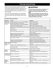
... Drain fuel & replace with fresh fuel. Safety interlock switch faulty. Contact Sears Parts & Repair Replace. Spark plug faulty, fouled, or incorrectly gapped. Clean and .... Move choke to OPEN position when cranking engine. Ignition switch not turned fully to cool, then refill the fuel tank. Allow engine to START...oil. Whilenormacl areandregularmaintenancweillextend the lifeofyourequipmenpt,rolongedor constanut se mayeventuallryequirethatservicebeperformetdo allow itto continueoperatingproperlyT. Mower blade switch in OFF position. Set choke to START/PARK. Iconsumption, Clean...
... Drain fuel & replace with fresh fuel. Safety interlock switch faulty. Contact Sears Parts & Repair Replace. Spark plug faulty, fouled, or incorrectly gapped. Clean and .... Move choke to OPEN position when cranking engine. Ignition switch not turned fully to cool, then refill the fuel tank. Allow engine to START...oil. Whilenormacl areandregularmaintenancweillextend the lifeofyourequipmenpt,rolongedor constanut se mayeventuallryequirethatservicebeperformetdo allow itto continueoperatingproperlyT. Mower blade switch in OFF position. Set choke to START/PARK. Iconsumption, Clean...
Operation Manual
Page 38
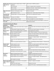
...not inflated equally or properly. Replace drive belt, PTO clutch out of balance, Cut grass with mower engaged. Parking brake will not positions. Contact Sears Parts & Repair. See Maintenance Section. Blades not properly fastened to one side. Decrease Ground Speed, ...Cut tall grass at maximum cutting height during first pass, Remove mower deck and clean underside, Excessive mower vibration, Discharge chute jamming ...
...not inflated equally or properly. Replace drive belt, PTO clutch out of balance, Cut grass with mower engaged. Parking brake will not positions. Contact Sears Parts & Repair. See Maintenance Section. Blades not properly fastened to one side. Decrease Ground Speed, ...Cut tall grass at maximum cutting height during first pass, Remove mower deck and clean underside, Excessive mower vibration, Discharge chute jamming ...

Operation Manual
Page 95
... Powdered Metal 1 ARM, Lift Trunnion 1 CARRIAGE BOLT, 5/16-18 x 1-1/2, G5 1 ARM, Mower Lift R.H. 1 NUT, Hex, 1/4-20 L.H. Lift Group REF NO PART NO, 4 1733535ASM 5 009X67MA 6 1931277SM 8 094067MA 9 1960170SM 10 1960074SM 11 1704420SM 12 1960687SM 13 ...1666294SM 14 1731894SM 15 1734217SM 16 1733356ASM 17 1673796SM 18 1734336ASM 19 1931337SM 20 1733536ASM 21 1960757SM 22 1921319SM 23 1733513SM 24 1722460SM 25 1733572SM 26...
... Powdered Metal 1 ARM, Lift Trunnion 1 CARRIAGE BOLT, 5/16-18 x 1-1/2, G5 1 ARM, Mower Lift R.H. 1 NUT, Hex, 1/4-20 L.H. Lift Group REF NO PART NO, 4 1733535ASM 5 009X67MA 6 1931277SM 8 094067MA 9 1960170SM 10 1960074SM 11 1704420SM 12 1960687SM 13 ...1666294SM 14 1731894SM 15 1734217SM 16 1733356ASM 17 1673796SM 18 1734336ASM 19 1931337SM 20 1733536ASM 21 1960757SM 22 1921319SM 23 1733513SM 24 1722460SM 25 1733572SM 26...

Operation Manual
Page 99
...289920 QTY. DESCRIPTION 1 DECAL Danger Do Not Put Hands/Feet in Mower (English/French) 1 DECAL 52" 1 DECAL OPEl Certified ANSI 1 DECAL Transmission Release Instructions (English/French) 1 DECAL Craftsman ZTS 1 DECAL Operator Instructions Upper (English/French) 1 DECAL Operator ...Instructions Lower (English/French) 1 DECAL Tracking Adjustment 1 DECAL Powered by 26HP 1 DECAL Height of Cut 1 LITERATURE PACK, SEARS ZTS 6000 26/52 (Not Shown) 1 DECAL, Craftsman Logo 1 DECAL...
...289920 QTY. DESCRIPTION 1 DECAL Danger Do Not Put Hands/Feet in Mower (English/French) 1 DECAL 52" 1 DECAL OPEl Certified ANSI 1 DECAL Transmission Release Instructions (English/French) 1 DECAL Craftsman ZTS 1 DECAL Operator Instructions Upper (English/French) 1 DECAL Operator ...Instructions Lower (English/French) 1 DECAL Tracking Adjustment 1 DECAL Powered by 26HP 1 DECAL Height of Cut 1 LITERATURE PACK, SEARS ZTS 6000 26/52 (Not Shown) 1 DECAL, Craftsman Logo 1 DECAL...

Operation Manual
Page 101
...1927557SM 6 NUT, Hex Flange, 5/16-18 7 1931335SM 4 BOLT, Carriage, 5/16-18 x 1 8 1737229BMYP 2 PLATE, Backing 9 1737439BMYP 1 UPSTOP, Front, 52" Mower lO 1736539YP 4 BOLT, Shoulder, 3/8-16 x 3-7/8 11 1960170SM 4 WASHER 1/2 12 1736896YP 4 WHEEL, Gauge, 5" 13 1960687SM 4 NUT, Hex Flange, 3/8-16 ...ARM, Idler 45 1736516YP 1 V-BELT, HA 132" 46 1737415YP 1 SPRING, Extension, PTO 52 1933685SM 1 CAPSCREW, Hex Head, 3/8-16 x 2-1/2 54 1960339SM 8 NUT, Hex Flange, 3/8-16 ZTS 6000-107.289920 Footnotes PTS-25 Clutch & Support Group REF NO PART NO. QTY.
...1927557SM 6 NUT, Hex Flange, 5/16-18 7 1931335SM 4 BOLT, Carriage, 5/16-18 x 1 8 1737229BMYP 2 PLATE, Backing 9 1737439BMYP 1 UPSTOP, Front, 52" Mower lO 1736539YP 4 BOLT, Shoulder, 3/8-16 x 3-7/8 11 1960170SM 4 WASHER 1/2 12 1736896YP 4 WHEEL, Gauge, 5" 13 1960687SM 4 NUT, Hex Flange, 3/8-16 ...ARM, Idler 45 1736516YP 1 V-BELT, HA 132" 46 1737415YP 1 SPRING, Extension, PTO 52 1933685SM 1 CAPSCREW, Hex Head, 3/8-16 x 2-1/2 54 1960339SM 8 NUT, Hex Flange, 3/8-16 ZTS 6000-107.289920 Footnotes PTS-25 Clutch & Support Group REF NO PART NO. QTY.

Operation Manual
Page 103
...52" 16 1735752YP 1 COVER, Belt 17 1736364YP 1 SPRING, Torsion Deflector 18 1736366YP 1 ROD, Deflector 19 1736505YP 1 COVER, Belt, Left 20 1736898YP 1 WASHOUT PORT, Connector 21 1737252AYP 3 BLADE, Mower 22 1737279BMYP 1 BAFFLE, Pinchoff 23 1737418BMYP 1 HINGE, Deflector 24 1920676SM 3 CAPSCREW, Hex, 7/16-14 x 1 25 1930600SM 2 SCREW, Hex Washer Head, Taptit, 5/16-18 x 1-1/2 26... Cover, Rear 36 1931333SM 2 BOLT, Round Head Shoulder, 5/16-18 x 3/4 ZTS 6000-107.289920 Footnotes PTS-27 Housing & Arbor Group REF NO PART NO. 52" Mower Deck - QTY.
...52" 16 1735752YP 1 COVER, Belt 17 1736364YP 1 SPRING, Torsion Deflector 18 1736366YP 1 ROD, Deflector 19 1736505YP 1 COVER, Belt, Left 20 1736898YP 1 WASHOUT PORT, Connector 21 1737252AYP 3 BLADE, Mower 22 1737279BMYP 1 BAFFLE, Pinchoff 23 1737418BMYP 1 HINGE, Deflector 24 1920676SM 3 CAPSCREW, Hex, 7/16-14 x 1 25 1930600SM 2 SCREW, Hex Washer Head, Taptit, 5/16-18 x 1-1/2 26... Cover, Rear 36 1931333SM 2 BOLT, Round Head Shoulder, 5/16-18 x 3/4 ZTS 6000-107.289920 Footnotes PTS-27 Housing & Arbor Group REF NO PART NO. 52" Mower Deck - QTY.


