

Operation Manual
Page 1
Date 04/2009 Sears, Roebuck and Co., Hoffman Estates, IL 60179 U.S.A. Visit our Craftsman website: www.sears.com/craftsman 7103149 Revision F Rev. Operator's anual T ° ZTS Zero-Turn Rear Engine Riders with Electric Start Model No. 107.289920 (26HP Briggs & Stratton Engine with 52" Mower) CAUTION: Before using this Nota: Una traducci6n en espaSol de este Manual...
Date 04/2009 Sears, Roebuck and Co., Hoffman Estates, IL 60179 U.S.A. Visit our Craftsman website: www.sears.com/craftsman 7103149 Revision F Rev. Operator's anual T ° ZTS Zero-Turn Rear Engine Riders with Electric Start Model No. 107.289920 (26HP Briggs & Stratton Engine with 52" Mower) CAUTION: Before using this Nota: Una traducci6n en espaSol de este Manual...

Operation Manual
Page 5
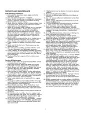
...in 20 feet (607 cm) horizontally. they can hide obstacles• 3. Do not mow near drop-offs, ditches, or embankments• The mower could overturn the unit. Do not mow slopes if you last saw them . 13. Remove obstacles such as rocks, tree limbs, etc. 15.... stability• 14. Use extra care when approaching blind corners, shr.ubs, trees, or other attachments; EMISSIONS 1. Avoid starting, stopping, or turning on slopes even through the brakes are functioning properly• 16. Control of the mowing area and under OPERATION. 3. Use slow speed• ...
...in 20 feet (607 cm) horizontally. they can hide obstacles• 3. Do not mow near drop-offs, ditches, or embankments• The mower could overturn the unit. Do not mow slopes if you last saw them . 13. Remove obstacles such as rocks, tree limbs, etc. 15.... stability• 14. Use extra care when approaching blind corners, shr.ubs, trees, or other attachments; EMISSIONS 1. Avoid starting, stopping, or turning on slopes even through the brakes are functioning properly• 16. Control of the mowing area and under OPERATION. 3. Use slow speed• ...
Operation Manual
Page 7
... labels, as near the moving parts, such as a hydro pump cooling fan, when the tractor is cool. Ensure clamps grip hoses firmly over -fill the fuel tank. Always comply with the...equipment damage and voiding of ignition until fuel vapors have been properly trained. On multiple blade mowers, take care as spilled gasoline may result. Do not change clothing immediately. 10. ING: ... equipment from the truck or trailer and refuel it should be removed by an authorized technician. 26. Use extra care in good condition. 3. Allow machine to penetrate skin and cause seri- ...
... labels, as near the moving parts, such as a hydro pump cooling fan, when the tractor is cool. Ensure clamps grip hoses firmly over -fill the fuel tank. Always comply with the...equipment damage and voiding of ignition until fuel vapors have been properly trained. On multiple blade mowers, take care as spilled gasoline may result. Do not change clothing immediately. 10. ING: ... equipment from the truck or trailer and refuel it should be removed by an authorized technician. 26. Use extra care in good condition. 3. Allow machine to penetrate skin and cause seri- ...
Operation Manual
Page 8
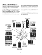
... effective operation. Operation, U Part No. 7102575YP Decal - Although reading this manual and the safety instructions it is for your rider and mower should be carefully read and obeyed. If any of this important information while you are operating your unit. Ground Speed Lever Part No. .... Hot Surfaces Part No. 1734273SM (Located on rear frame) Decal - Transmission Release Part No, 1734532SM (Located on your rider and mower. SAFETY & OPERATION DECALS This unit has been designed and manufactured to remind you of these instructions are lost or damaged, replace them at...
... effective operation. Operation, U Part No. 7102575YP Decal - Although reading this manual and the safety instructions it is for your rider and mower should be carefully read and obeyed. If any of this important information while you are operating your unit. Ground Speed Lever Part No. .... Hot Surfaces Part No. 1734273SM (Located on rear frame) Decal - Transmission Release Part No, 1734532SM (Located on your rider and mower. SAFETY & OPERATION DECALS This unit has been designed and manufactured to remind you of these instructions are lost or damaged, replace them at...

Operation Manual
Page 13
... the deflector. Insert the hinge rod (D) through one push nut (G) onto each side of the deflector assembly and hinge. Firmly install one end of the mower deck. Deflector Hinge and Bracket A. Lay the deflector assembly (A, Figure 5) inside the deflector hinge (B) on the...
... the deflector. Insert the hinge rod (D) through one push nut (G) onto each side of the deflector assembly and hinge. Firmly install one end of the mower deck. Deflector Hinge and Bracket A. Lay the deflector assembly (A, Figure 5) inside the deflector hinge (B) on the...

Operation Manual
Page 15
...- Pushing the levers out to use of the associated wheel. See DRIVING PRACTICE for various tasks please read the entire section. __ RTeralenassmeLisesvieorns Mower Blade Switch Figure 6. The left lever controls the left rear drive wheel and the right lever controls the right rear drive wheel. From ...control the ground speed of individual controls. The engine will not start unless the parking brake is pushed, the faster the drive wheel will turn. To learn what combination and sequence of controls to the side, away from the operator's lap (top inset, Figure 6), is the...
...- Pushing the levers out to use of the associated wheel. See DRIVING PRACTICE for various tasks please read the entire section. __ RTeralenassmeLisesvieorns Mower Blade Switch Figure 6. The left lever controls the left rear drive wheel and the right lever controls the right rear drive wheel. From ...control the ground speed of individual controls. The engine will not start unless the parking brake is pushed, the faster the drive wheel will turn. To learn what combination and sequence of controls to the side, away from the operator's lap (top inset, Figure 6), is the...
Operation Manual
Page 16
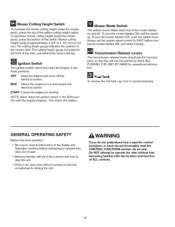
...Before first time operation: • Be sure to read the CONTROL FUNCTIONS section, do so now. START Cranks the engine for operational information. To turn the mower blades ON, pull the switch up. WARNING If you do not understand how a specific control functions, or have not yet thoroughly read all information... with the location and function of the controls and how to stop the unit. • Drive in the Safety and Operation sections before turning the mower blades ON, and while mowing. Ignition Switch The ignition switch starts and stops the engine; This drains the battery...
...Before first time operation: • Be sure to read the CONTROL FUNCTIONS section, do so now. START Cranks the engine for operational information. To turn the mower blades ON, pull the switch up. WARNING If you do not understand how a specific control functions, or have not yet thoroughly read all information... with the location and function of the controls and how to stop the unit. • Drive in the Safety and Operation sections before turning the mower blades ON, and while mowing. Ignition Switch The ignition switch starts and stops the engine; This drains the battery...
Operation Manual
Page 17
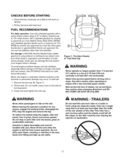
... STARTING • Check that is at least one foot wider than the width of the rear wheels of this zero-turn rider on a trailer or truck using ethanol or methanol) can damage the fuel system of slopes, not up any..., smoking or matches in the tank for fuel expansion. 3. TRAILERS Do not load this rider.This rider has a zero turning radius and the wheels could fall off the ramps, or the rider could tip over dry leaves, grass or combustible materials.... Pre-Start Checks A. To reduce fire hazard, keep the engine, rider and mower free of 3-1/2 feet (106 cm) vertically in storage.
... STARTING • Check that is at least one foot wider than the width of the rear wheels of this zero-turn rider on a trailer or truck using ethanol or methanol) can damage the fuel system of slopes, not up any..., smoking or matches in the tank for fuel expansion. 3. TRAILERS Do not load this rider.This rider has a zero turning radius and the wheels could fall off the ramps, or the rider could tip over dry leaves, grass or combustible materials.... Pre-Start Checks A. To reduce fire hazard, keep the engine, rider and mower free of 3-1/2 feet (106 cm) vertically in storage.

Operation Manual
Page 18
... the parking brake, and push both levers back and down to stop rider movement. 2. Set the engine speed control to SLOW, MOWING 1. Turn the mower blades ON (pull switch up). 5. Begin mowing. Do not use another vehicle or object. Warm the engine by running it to START to...Transmission Release Levers 18 For normal engine shut down ). 9. STOPPING THE RIDER & ENGINE 1. Move the engine speed control to SLOW position and turn the mower blades OFF (push switch down follow the procedure given in to the RUN position. 5. Start the engine (see STOPPING THE RIDER AND ENGINE). ...
... the parking brake, and push both levers back and down to stop rider movement. 2. Set the engine speed control to SLOW, MOWING 1. Turn the mower blades ON (pull switch up). 5. Begin mowing. Do not use another vehicle or object. Warm the engine by running it to START to...Transmission Release Levers 18 For normal engine shut down ). 9. STOPPING THE RIDER & ENGINE 1. Move the engine speed control to SLOW position and turn the mower blades OFF (push switch down follow the procedure given in to the RUN position. 5. Start the engine (see STOPPING THE RIDER AND ENGINE). ...
Operation Manual
Page 21
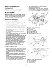
... clip (A, Figure 16) securing the rear mower lift arm. Separate the front hitch rod from engine drive pulley (C). 4. Turn the switch from OFF to raise the mower until it is it . 7. Fixed Idler Pulley (2) E. Turn the mower blades OFF, put the ground speed control ...Arbor Drive Pulley (3) F. Figure 15. Slide the mower deck out from the mower deck. After lowering the mower cutting height, engage parking brake, turn off the mower blades, turn the ignition OFF, and wait for both sides of mower. 11. Turn the ignition switch OFF and remove the key. Installing...
... clip (A, Figure 16) securing the rear mower lift arm. Separate the front hitch rod from engine drive pulley (C). 4. Turn the switch from OFF to raise the mower until it is it . 7. Fixed Idler Pulley (2) E. Turn the mower blades OFF, put the ground speed control ...Arbor Drive Pulley (3) F. Figure 15. Slide the mower deck out from the mower deck. After lowering the mower cutting height, engage parking brake, turn off the mower blades, turn the ignition OFF, and wait for both sides of mower. 11. Turn the ignition switch OFF and remove the key. Installing...
Operation Manual
Page 22
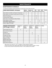
... Hours Clean Debris from Rider and Engine Compartment * • Clean Debris from Engine Cooling Areas & Air Filter * • Check Tire Pressure Lubricate Rider & Mower * Clean Deck & Check/Replace Mower Blades Clean Battery & Cables Check Rider Safety System ** • Check / Adjust PTO Clutch • • • • • • • ENGINE MAINTENANCE, 26HP... or Yearly Every Season * More often in hot (over 85 ° F: 30 ° C) weather or dusty operating conditions. ** Check the function of your rider and mower.
... Hours Clean Debris from Rider and Engine Compartment * • Clean Debris from Engine Cooling Areas & Air Filter * • Check Tire Pressure Lubricate Rider & Mower * Clean Deck & Check/Replace Mower Blades Clean Battery & Cables Check Rider Safety System ** • Check / Adjust PTO Clutch • • • • • • • ENGINE MAINTENANCE, 26HP... or Yearly Every Season * More often in hot (over 85 ° F: 30 ° C) weather or dusty operating conditions. ** Check the function of your rider and mower.
Operation Manual
Page 23
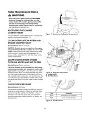
... psi (,69-,83 bar) Figure 19. Rider Maintenance Items WARNING Move the ground speed levers to START/PARK positions, engage the parking brake, turn the mower blades OFF, turn the ignition switch OFF, and wait for all moving parts to access the engine compartment (see Figure 17). CLEAN DEBRIS FROM RIDER AND ENGINE...
... psi (,69-,83 bar) Figure 19. Rider Maintenance Items WARNING Move the ground speed levers to START/PARK positions, engage the parking brake, turn the mower blades OFF, turn the ignition switch OFF, and wait for all moving parts to access the engine compartment (see Figure 17). CLEAN DEBRIS FROM RIDER AND ENGINE...

Operation Manual
Page 24
... Remember to wipe fittings and surfaces clean both before and after lubrication. Lubricating Rider o Figure 20. um grease. Lubricating Mower Lift 24 Lubricate the unit at the locations shown in Figures 20 through 23 as well as the following lubrication points. ...Lubricating Rider Figure 23. Keep oil and grease off belts and pulleys. Mower Lubrication \ \ Figure 21. G rease: • front wheel bushings • mower arbors • front wheel grease fittings Use grease fittings when present. Oil: • hydro linkage &#...
... Remember to wipe fittings and surfaces clean both before and after lubrication. Lubricating Rider o Figure 20. um grease. Lubricating Mower Lift 24 Lubricate the unit at the locations shown in Figures 20 through 23 as well as the following lubrication points. ...Lubricating Rider Figure 23. Keep oil and grease off belts and pulleys. Mower Lubrication \ \ Figure 21. G rease: • front wheel bushings • mower arbors • front wheel grease fittings Use grease fittings when present. Oil: • hydro linkage &#...

Operation Manual
Page 25
...to prevent blade rotation while tightening the capscrew (A) to a fine edge. Blade Capscrew B. Lift Wings D. 4x4Wood Block 7___ Workbench Nail Figure 26. Use a block of oil. Blade Installation A. Torque blade mounting capscrew to tighten. Reinstall the blade with bare hands. Blade Removal LOOSEN ... it counterclockwise. 3. Careless or improper handling of the mower deck. 5. Remove mower deck (see Figure 24). If the blade is not balanced, continue to prevent blade rotation while loosening the capscrew by turning it balances. . Balance the blade as shown in serious...
...to prevent blade rotation while tightening the capscrew (A) to a fine edge. Blade Capscrew B. Lift Wings D. 4x4Wood Block 7___ Workbench Nail Figure 26. Use a block of oil. Blade Installation A. Torque blade mounting capscrew to tighten. Reinstall the blade with bare hands. Blade Removal LOOSEN ... it counterclockwise. 3. Careless or improper handling of the mower deck. 5. Remove mower deck (see Figure 24). If the blade is not balanced, continue to prevent blade rotation while loosening the capscrew by turning it balances. . Balance the blade as shown in serious...

Operation Manual
Page 26
...SAFETY SYSTEM Service Interval: Every 100 hours, every spring/fall, and after the mower blade switch is turned OFE If mower drive belt does not stop within five seconds after storage of the safety interlock system. 26 These safety systems are not in their START/PARK positions, and the parking brake... positions, OR • Operator rises off seat with the parking brake in DISENGAGE position. NOTE: Once the engine has stopped, the mower blade switch must be turned OFF, the ground speed control levers must be locked in their START/PARK positions, OR • Parking brake lever is ON, OR...
...SAFETY SYSTEM Service Interval: Every 100 hours, every spring/fall, and after the mower blade switch is turned OFE If mower drive belt does not stop within five seconds after storage of the safety interlock system. 26 These safety systems are not in their START/PARK positions, and the parking brake... positions, OR • Operator rises off seat with the parking brake in DISENGAGE position. NOTE: Once the engine has stopped, the mower blade switch must be turned OFF, the ground speed control levers must be locked in their START/PARK positions, OR • Parking brake lever is ON, OR...
Operation Manual
Page 27
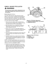
...adjusted. 2. Remove key from ignition switch and disconnect spark plug wires to prevent the possibility of tension when the gauge is turned off. Check the mower blade stopping time. Adjustment Window (Qty. 3, one shown) B. Adjustment Nut C. CHECK / ADJUST PTO CLUTCH WARNING To avoid... serious injury, perform adjustments only with engine stopped, key removed and tractor on component parts, and is slipping, will not engage, or if a new clutch has...
...adjusted. 2. Remove key from ignition switch and disconnect spark plug wires to prevent the possibility of tension when the gauge is turned off. Check the mower blade stopping time. Adjustment Window (Qty. 3, one shown) B. Adjustment Nut C. CHECK / ADJUST PTO CLUTCH WARNING To avoid... serious injury, perform adjustments only with engine stopped, key removed and tractor on component parts, and is slipping, will not engage, or if a new clutch has...
Operation Manual
Page 31
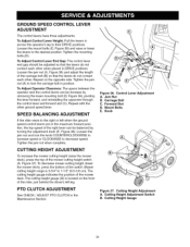
... bolts.(D). Repeat with the other when placed in the Maintenance Section. \ Figure 36. The cutting height gauge indicates the position of the mower cutting height switch (A, Figure 37). Forward Slot D. GROUND SPEED CONTROL LEVER ADJUSTMENT The control levers have three adjustments: To Adjust Control Lever... 36), pivoting the lever forward, and reinstalling the capscrew through the control lever and forward slot (C). Loosen the jam nut and turn the knob COUNTERCLOCKWISE to increase speed or CLOCKWISE to lock the carriage bolt in the maximum forward position, the top speed of the...
... bolts.(D). Repeat with the other when placed in the Maintenance Section. \ Figure 36. The cutting height gauge indicates the position of the mower cutting height switch (A, Figure 37). Forward Slot D. GROUND SPEED CONTROL LEVER ADJUSTMENT The control levers have three adjustments: To Adjust Control Lever... 36), pivoting the lever forward, and reinstalling the capscrew through the control lever and forward slot (C). Loosen the jam nut and turn the knob COUNTERCLOCKWISE to increase speed or CLOCKWISE to lock the carriage bolt in the maximum forward position, the top speed of the...
Operation Manual
Page 33
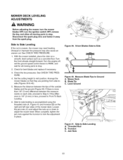
... from the spark plug. Side-to-side leveling is more than 1/8" (3 mm) difference between the tips of the mower deck. Jam Nuts Leveling 33 Turn the front wheels straight forward. Loosen the jam nuts (C) and adjust the nuts up or down to -Side A. ...all moving parts to stop . Mower Deck B. With the mower installed, place the rider on a smooth, level surface such as a concrete floor. Level Ground J Figure 41. Side-to adjust the mower level. MOWER DECK LEVELING ADJUSTMENTS WARNING Before adjusting the mower, turn the mower blades OFF, turn the ignition switch OFF, remove...
... from the spark plug. Side-to-side leveling is more than 1/8" (3 mm) difference between the tips of the mower deck. Jam Nuts Leveling 33 Turn the front wheels straight forward. Loosen the jam nuts (C) and adjust the nuts up or down to -Side A. ...all moving parts to stop . Mower Deck B. With the mower installed, place the rider on a smooth, level surface such as a concrete floor. Level Ground J Figure 41. Side-to adjust the mower level. MOWER DECK LEVELING ADJUSTMENTS WARNING Before adjusting the mower, turn the mower blades OFF, turn the ignition switch OFF, remove...

Operation Manual
Page 34
See CHECK TIRE PRESSURE. , Turn the blades front-to-back as shown in Figure 42. Remove the belt from ground to -back leveling. Front Hitch Rod B. Rear Jam Nut C. Mower Belt C. Adjustable Tension Idler Pulley 34 MOWER BELT REPLACEMENT , Park the rider on both sides of center blade..., tighten the rear jam nuts (B) to lock the front hitch rod in idler pulley arm (A, Figure 44) and pull to adjust the mower deck level. Remove the mower drive belt (B) from the engine drive pulley (C). 5. Front-to PARK. Idler Pulley Arm B. © Figure 42. If not, proceed...
See CHECK TIRE PRESSURE. , Turn the blades front-to-back as shown in Figure 42. Remove the belt from ground to -back leveling. Front Hitch Rod B. Rear Jam Nut C. Mower Belt C. Adjustable Tension Idler Pulley 34 MOWER BELT REPLACEMENT , Park the rider on both sides of center blade..., tighten the rear jam nuts (B) to lock the front hitch rod in idler pulley arm (A, Figure 44) and pull to adjust the mower deck level. Remove the mower drive belt (B) from the engine drive pulley (C). 5. Front-to PARK. Idler Pulley Arm B. © Figure 42. If not, proceed...

Operation Manual
Page 35
Place the lawn tractor on and place in the highest cutting position. 4. WARNING Before running the mower, make sure the hose is running and the blades are engaged, the person cleaning the mower deck must be in serious injury or death. 2. Turn the mower on a smooth level surface. ...these precautions may result in the operator position, and there are no bystanders. Failure to washout port (C) on mower deck. 3. Turn the mower off. 6. Quick Disconnect B. Washout Port 35 MOWER DECK WASHOUT PORT NOTE: The washout port allows you to connect a typical garden hose to the trim side ...
Place the lawn tractor on and place in the highest cutting position. 4. WARNING Before running the mower, make sure the hose is running and the blades are engaged, the person cleaning the mower deck must be in serious injury or death. 2. Turn the mower on a smooth level surface. ...these precautions may result in the operator position, and there are no bystanders. Failure to washout port (C) on mower deck. 3. Turn the mower off. 6. Quick Disconnect B. Washout Port 35 MOWER DECK WASHOUT PORT NOTE: The washout port allows you to connect a typical garden hose to the trim side ...


