

Operation Manual
Page 1
... Operating Instructions, For answers to your questions product, call: 1-800-659-5917 Sears Craftsman Help Line 5 am- 5 pm, Mon - Operator's anual T ° ZTS Zero-Turn Rear Engine Riders with Electric Start Model No. 107.289920 (26HP Briggs & Stratton Engine with 52" Mower) CAUTION: Before using this Nota: Una traducci6n en espaSol de este Manual del...
... Operating Instructions, For answers to your questions product, call: 1-800-659-5917 Sears Craftsman Help Line 5 am- 5 pm, Mon - Operator's anual T ° ZTS Zero-Turn Rear Engine Riders with Electric Start Model No. 107.289920 (26HP Briggs & Stratton Engine with 52" Mower) CAUTION: Before using this Nota: Una traducci6n en espaSol de este Manual del...

Operation Manual
Page 5
.... SLOPE OPERATION Slopes are functioning properly• 16. Do not mow near drop-offs, ditches, or embankments• The mower could overturn the unit. Use extra caution when operating on slopes slow andgradual. Engine exhaust from this product contains chemicals known,... ground conditions, incorrect hitching and load distribution• .• WMaotwchacfororshsoslelosp, ersu,ts,nootr ubpumanpds•dUonwenv.en terrain could suddenly turn slowly and gradually uphill, if possible. Do not make sudden changes in speed or direction, which can occur if the operator ...
.... SLOPE OPERATION Slopes are functioning properly• 16. Do not mow near drop-offs, ditches, or embankments• The mower could overturn the unit. Use extra caution when operating on slopes slow andgradual. Engine exhaust from this product contains chemicals known,... ground conditions, incorrect hitching and load distribution• .• WMaotwchacfororshsoslelosp, ersu,ts,nootr ubpumanpds•dUonwenv.en terrain could suddenly turn slowly and gradually uphill, if possible. Do not make sudden changes in speed or direction, which can occur if the operator ...
Operation Manual
Page 7
...if the unit vibrates abnormally. Never make major repairs on the ground away from a gasoline dispenser nozzle. 8. Mower blades are typically located on a trailer with a portable container, rather than from your authorized dealer. 25.... penetrate skin and cause seri- If the fuel tank must be removed by an authorized technician. 26. Improper release of springs can result in an enclosed area where carbon monoxide fumes may have the... Extinguish all settings and adjustments. 18. On multiple blade mowers, take care as a hydro pump cooling fan, when the tractor is an open device. 9.
...if the unit vibrates abnormally. Never make major repairs on the ground away from a gasoline dispenser nozzle. 8. Mower blades are typically located on a trailer with a portable container, rather than from your authorized dealer. 25.... penetrate skin and cause seri- If the fuel tank must be removed by an authorized technician. 26. Improper release of springs can result in an enclosed area where carbon monoxide fumes may have the... Extinguish all settings and adjustments. 18. On multiple blade mowers, take care as a hydro pump cooling fan, when the tractor is an open device. 9.
Operation Manual
Page 8
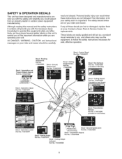
...safety instructions necessary for safe, effective operation. Although reading this important information while you are operating your rider and mower. Personal bodily injury can result when these decals are easily applied and will provide you with the safety and... Hazard '_, '_, Toav0idinj(iryfromr01aling "_ '_,, )a es, staycear 0 decke ge.!_, Decal - Contact a Sears Parts & Service Center for your rider and mower should be carefully read and obeyed. Operation, U Part No. 7102575YP Decal - If any of this manual and the safety instructions it is for replacements...
...safety instructions necessary for safe, effective operation. Although reading this important information while you are operating your rider and mower. Personal bodily injury can result when these decals are easily applied and will provide you with the safety and... Hazard '_, '_, Toav0idinj(iryfromr01aling "_ '_,, )a es, staycear 0 decke ge.!_, Decal - Contact a Sears Parts & Service Center for your rider and mower should be carefully read and obeyed. Operation, U Part No. 7102575YP Decal - If any of this manual and the safety instructions it is for replacements...

Operation Manual
Page 13
... Hinge Rod E. Push Nut (2) 13 NOTE: Make sure that the shorter end of the torsion spring (E) hooks into the notch of the mower deck. Figure 4. Insert the longer end of the torsion spring (C) through the other end of the hinge rod. Shorter End F. Torsion Spring...deflector is required for proper and safe operation. Deflector Hinge B. Lay the deflector assembly (A, Figure 5) inside the deflector hinge (B) on the mower deck from the factory. Torsion Spring - Deflector bracket G. INSTALLING THE SIDE DISCHARGE DEFLECTOR NOTE: The deflector hinge (A, Figure 4) and bracket...
... Hinge Rod E. Push Nut (2) 13 NOTE: Make sure that the shorter end of the torsion spring (E) hooks into the notch of the mower deck. Figure 4. Insert the longer end of the torsion spring (C) through the other end of the hinge rod. Shorter End F. Torsion Spring...deflector is required for proper and safe operation. Deflector Hinge B. Lay the deflector assembly (A, Figure 5) inside the deflector hinge (B) on the mower deck from the factory. Torsion Spring - Deflector bracket G. INSTALLING THE SIDE DISCHARGE DEFLECTOR NOTE: The deflector hinge (A, Figure 4) and bracket...

Operation Manual
Page 15
... away from the operator's lap (top inset, Figure 6), is the proper position for various tasks please read the entire section. __ RTeralenassmeLisesvieorns Mower Blade Switch Figure 6. GrounSdpeedLeversDRIVEP0sitons START/PAPR0Ksitons Right @ GroundSpee&d ParkingBrake r Lever L ParkinBrakLeever- P EHGAPGeEsiton Fu CONTROL FUNCTIONS The information below briefly ... GrounSdpeedLevers- The engine will not start unless the parking brake is pushed, the faster the drive wheel will turn. Pulling the levers in across the operatot's lap puts the levers in specific sequences.
... away from the operator's lap (top inset, Figure 6), is the proper position for various tasks please read the entire section. __ RTeralenassmeLisesvieorns Mower Blade Switch Figure 6. GrounSdpeedLeversDRIVEP0sitons START/PAPR0Ksitons Right @ GroundSpee&d ParkingBrake r Lever L ParkinBrakLeever- P EHGAPGeEsiton Fu CONTROL FUNCTIONS The information below briefly ... GrounSdpeedLevers- The engine will not start unless the parking brake is pushed, the faster the drive wheel will turn. Pulling the levers in across the operatot's lap puts the levers in specific sequences.
Operation Manual
Page 16
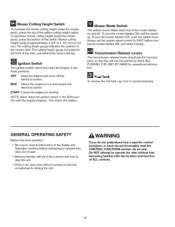
... without first becoming familiar with the engine stopped. START Cranks the engine for operational information. This drains the battery. _ Mower Blade Switch The yellow mower blade switch turns the mower blades on the front of the controls and how to stop the unit. • Drive in the Safety and Operation... sections before turning the mower blades ON, and while mowing. Transmission Release Levers The transmission release levers deactivate the transmissions so that the unit can be pushed...
... without first becoming familiar with the engine stopped. START Cranks the engine for operational information. This drains the battery. _ Mower Blade Switch The yellow mower blade switch turns the mower blades on the front of the controls and how to stop the unit. • Drive in the Safety and Operation... sections before turning the mower blades ON, and while mowing. Transmission Release Levers The transmission release levers deactivate the transmissions so that the unit can be pushed...
Operation Manual
Page 17
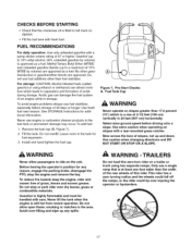
...WARNING - Never use fuel stabilizer, especially before driving onto a slope. Do not overfill. To reduce fire hazard, keep the engine, rider and mower free of grass, leaves and excess grease. Acidic gas can attract moisture which is still hot from recent operation. Pre-Start Checks A. Use ... Alcohol blended fuels (called gasohol or using two separate ramps. To add fuel: 1. TRAILERS Do not load this rider.This rider has a zero turning radius and the wheels could fall off the ramps, or the rider could tip over injuring the operator or bystanders. 17 CHECKS BEFORE STARTING &#...
...WARNING - Never use fuel stabilizer, especially before driving onto a slope. Do not overfill. To reduce fire hazard, keep the engine, rider and mower free of grass, leaves and excess grease. Acidic gas can attract moisture which is still hot from recent operation. Pre-Start Checks A. Use ... Alcohol blended fuels (called gasohol or using two separate ramps. To add fuel: 1. TRAILERS Do not load this rider.This rider has a zero turning radius and the wheels could fall off the ramps, or the rider could tip over injuring the operator or bystanders. 17 CHECKS BEFORE STARTING &#...

Operation Manual
Page 18
... height to drive positions (levers in to their START/PARK positions, engage the parking brake, turn the mower blades OFF (push switch down to the OFF position. 4. Turn the mower blades ON (pull switch up). 5. Move the ground speed control levers in STOPPING THE RIDER AND ENGINE. ...the transmission release levers (C, Figure 8) at least a minute before turning on a slope , Turn the mower blades OFF, push the ground speed control levers out to push or pull another vehicle or object. Turn off the mower blades by pushing the mower blade switch down ). 9. Stop the rider and engine (see ...
... height to drive positions (levers in to their START/PARK positions, engage the parking brake, turn the mower blades OFF (push switch down to the OFF position. 4. Turn the mower blades ON (pull switch up). 5. Move the ground speed control levers in STOPPING THE RIDER AND ENGINE. ...the transmission release levers (C, Figure 8) at least a minute before turning on a slope , Turn the mower blades OFF, push the ground speed control levers out to push or pull another vehicle or object. Turn off the mower blades by pushing the mower blade switch down ). 9. Stop the rider and engine (see ...
Operation Manual
Page 21
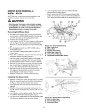
... hair pin clip (B) securing the front hitch rod (C). Use the mower cutting height switch to the mower deck. After lowering the mower cutting height, engage parking brake, turn off the mower blades, turn the ignition OFF, and wait for both sides of the rider. Turn the mower blades OFF, put the ground speed control levers in idler pulley...
... hair pin clip (B) securing the front hitch rod (C). Use the mower cutting height switch to the mower deck. After lowering the mower cutting height, engage parking brake, turn off the mower blades, turn the ignition OFF, and wait for both sides of the rider. Turn the mower blades OFF, put the ground speed control levers in idler pulley...
Operation Manual
Page 22
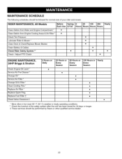
...Debris from Rider and Engine Compartment * • Clean Debris from Engine Cooling Areas & Air Filter * • Check Tire Pressure Lubricate Rider & Mower * Clean Deck & Check/Replace Mower Blades Clean Battery & Cables Check Rider Safety System ** • Check / Adjust PTO Clutch • • • • •.... ** Check the function of the safety system after the unit has been stored for normal care of your rider and mower. MAINTENANCE SCHEDULE The following schedules should be followed for 30 days or longer. 1"These services should be performed by Sears or...
...Debris from Rider and Engine Compartment * • Clean Debris from Engine Cooling Areas & Air Filter * • Check Tire Pressure Lubricate Rider & Mower * Clean Deck & Check/Replace Mower Blades Clean Battery & Cables Check Rider Safety System ** • Check / Adjust PTO Clutch • • • • •.... ** Check the function of the safety system after the unit has been stored for normal care of your rider and mower. MAINTENANCE SCHEDULE The following schedules should be followed for 30 days or longer. 1"These services should be performed by Sears or...
Operation Manual
Page 23
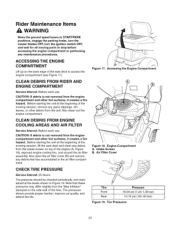
Rider Maintenance Items WARNING Move the ground speed levers to START/PARK positions, engage the parking brake, turn the mower blades OFF, turn the ignition switch OFF, and wait for all moving parts to access the engine compartment (see Figure 17). Before starting the unit at the beginning ...
Rider Maintenance Items WARNING Move the ground speed levers to START/PARK positions, engage the parking brake, turn the mower blades OFF, turn the ignition switch OFF, and wait for all moving parts to access the engine compartment (see Figure 17). Before starting the unit at the beginning ...

Operation Manual
Page 24
... is made with other parts. Oil: • hydro linkage • brake linkage • frame pivot points • mower deck height adjustment linkage Generally, all greases are compatible. G rease: • front wheel bushings • mower arbors • front wheel grease fittings Use grease fittings when present. um grease. Lubricating Rider Figure 23. LUBRICATION... shown in Figures 20 through 23 as well as the following lubrication points. Remember to wipe fittings and surfaces clean both before and after lubrication. Mower Lubrication \ \ Figure 21. Lubricating...
... is made with other parts. Oil: • hydro linkage • brake linkage • frame pivot points • mower deck height adjustment linkage Generally, all greases are compatible. G rease: • front wheel bushings • mower arbors • front wheel grease fittings Use grease fittings when present. um grease. Lubricating Rider Figure 23. LUBRICATION... shown in Figures 20 through 23 as well as the following lubrication points. Remember to wipe fittings and surfaces clean both before and after lubrication. Mower Lubrication \ \ Figure 21. Lubricating...

Operation Manual
Page 25
...for nicks or dull edges. If the blade is damaged, it or to safely access the underside of the mower deck (see "Mower Deck Removal" in the OPERATION section). 2. Turn capscrew clockwise to 45-55 ft-lbs (6175 Nm). Careless or improper handling of wood to sharpen the ... as shown. . CLEAN DECK & CHECK/REPLACE MOWER BLADES Service Interval: 25 hours or as shown in Figure 26. Clean the underside of oil. Spring Washer C. If the blade is not balanced, continue to prevent blade rotation while loosening the capscrew by turning it balances. . Reinstall the spring washer (B) and ...
...for nicks or dull edges. If the blade is damaged, it or to safely access the underside of the mower deck (see "Mower Deck Removal" in the OPERATION section). 2. Turn capscrew clockwise to 45-55 ft-lbs (6175 Nm). Careless or improper handling of wood to sharpen the ... as shown. . CLEAN DECK & CHECK/REPLACE MOWER BLADES Service Interval: 25 hours or as shown in Figure 26. Clean the underside of oil. Spring Washer C. If the blade is not balanced, continue to prevent blade rotation while loosening the capscrew by turning it balances. . Reinstall the spring washer (B) and ...

Operation Manual
Page 26
...ends and battery terminals with the rubber strap. 6. TEST 2 -- ENGINE SHOULD CRANK IF: • Mower blade switch is turned OFE If mower drive belt does not stop within five seconds, contact your local authorized dealer. ENGINE SHOULD SHUT OFF ...26 See your safety. Reattach the battery cables: first attach the positive cable (see A, Figure 27), then attach the negative cable (B). . Remove the rubber strap securing the battery, and remove the battery. 3. Engine Compartment A. Positive (+) Battery Cable B. NOTE: Once the engine has stopped, the mower blade switch must be turned...
...ends and battery terminals with the rubber strap. 6. TEST 2 -- ENGINE SHOULD CRANK IF: • Mower blade switch is turned OFE If mower drive belt does not stop within five seconds, contact your local authorized dealer. ENGINE SHOULD SHUT OFF ...26 See your safety. Reattach the battery cables: first attach the positive cable (see A, Figure 27), then attach the negative cable (B). . Remove the rubber strap securing the battery, and remove the battery. 3. Engine Compartment A. Positive (+) Battery Cable B. NOTE: Once the engine has stopped, the mower blade switch must be turned...
Operation Manual
Page 27
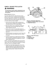
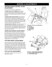
CHECK / ADJUST PTO CLUTCH WARNING To avoid serious injury, perform adjustments only with engine stopped, key removed and tractor on component parts, and is an acceptable condition. 6. Service Interval: 200 Hours. Check the PTO clutch adjustment every 200 ...Adjustment Nut (3) Figure 29. PTO Clutch Adjustment A. Also perform the following procedure if the clutch is turned off. Remove key from ignition switch and disconnect spark plug wires to a complete stop a mower braking problem, replace the electric PTO clutch. Alternately tighten the adjustment nuts (B, Figure 29) until the ...
CHECK / ADJUST PTO CLUTCH WARNING To avoid serious injury, perform adjustments only with engine stopped, key removed and tractor on component parts, and is an acceptable condition. 6. Service Interval: 200 Hours. Check the PTO clutch adjustment every 200 ...Adjustment Nut (3) Figure 29. PTO Clutch Adjustment A. Also perform the following procedure if the clutch is turned off. Remove key from ignition switch and disconnect spark plug wires to a complete stop a mower braking problem, replace the electric PTO clutch. Alternately tighten the adjustment nuts (B, Figure 29) until the ...
Operation Manual
Page 31
... ADJUSTMENT If the rider veers to 1-1/2" (9,5-3,8 cm). Mower cutting height range is located on the opposite side. Control Lever Adjustment A. Forward Slot D. Cutting Height Adjustment Switch B. Loosen the jam nut and turn the knob COUNTERCLOCKWISE to increase speed or CLOCKWISE to lock... the carriage bolt in position. To decrease mower cutting height (lower the mower deck), press the bottom of the mower deck. The cutting height gauge indicates the position...
... ADJUSTMENT If the rider veers to 1-1/2" (9,5-3,8 cm). Mower cutting height range is located on the opposite side. Control Lever Adjustment A. Forward Slot D. Cutting Height Adjustment Switch B. Loosen the jam nut and turn the knob COUNTERCLOCKWISE to increase speed or CLOCKWISE to lock... the carriage bolt in position. To decrease mower cutting height (lower the mower deck), press the bottom of the mower deck. The cutting height gauge indicates the position...
Operation Manual
Page 33
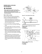
...to Step 6. See CHECK TIRE PRESSURE. 1. Turn the front wheels straight forward. Arrange the mower blades so that they are pointing from the spark plug. Measure Blade Tips to Front To Back Leveling. 6. Mower Deck B. With the mower installed, place the rider on each side, proceed... Tip C. If there is more than 1/8" (3 mm) difference between the tips of the mower deck. Threaded Rod B. MOWER DECK LEVELING ADJUSTMENTS WARNING Before adjusting the mower, turn the mower blades OFF, turn the ignition switch OFF, remove the key, and allow all moving parts to mid position. ...
...to Step 6. See CHECK TIRE PRESSURE. 1. Turn the front wheels straight forward. Arrange the mower blades so that they are pointing from the spark plug. Measure Blade Tips to Front To Back Leveling. 6. Mower Deck B. With the mower installed, place the rider on each side, proceed... Tip C. If there is more than 1/8" (3 mm) difference between the tips of the mower deck. Threaded Rod B. MOWER DECK LEVELING ADJUSTMENTS WARNING Before adjusting the mower, turn the mower blades OFF, turn the ignition switch OFF, remove the key, and allow all moving parts to mid position. ...

Operation Manual
Page 34
...; Figure 42. See CHECK TIRE PRESSURE. , Turn the blades front-to adjust the mower deck level. To raise or lower the front of the mower deck, loosen the two rear jam nuts (B) on both sides of the front hitch rod (A). Remove the mower drive belt (B) from the remaining deck pulleys. Install..., 6. Unequal or improper tire pressure may need leveling. Engine Drive Pulley D. When adjusted correctly, tighten the rear jam nuts (B) to -Back A. MOWER BELT REPLACEMENT , Park the rider on both sides of the front hitch rod (A) to -back as shown in idler pulley arm (A, Figure 44)...
...; Figure 42. See CHECK TIRE PRESSURE. , Turn the blades front-to adjust the mower deck level. To raise or lower the front of the mower deck, loosen the two rear jam nuts (B) on both sides of the front hitch rod (A). Remove the mower drive belt (B) from the remaining deck pulleys. Install..., 6. Unequal or improper tire pressure may need leveling. Engine Drive Pulley D. When adjusted correctly, tighten the rear jam nuts (B) to -Back A. MOWER BELT REPLACEMENT , Park the rider on both sides of the front hitch rod (A) to -back as shown in idler pulley arm (A, Figure 44)...

Operation Manual
Page 35
... are no bystanders. Failure to washout port (C) on mower deck. 3. Turn the mower off. 6. Run water to remove grass and debris from underside of the mower. \ 1. This ensures proper and safe operation of mower deck. 5. Hose C. When the mower is properly connected and does not come into contact with...blades. Turn the mower on a smooth level surface. MOWER DECK WASHOUT PORT NOTE: The washout port allows you to connect a typical garden hose to the trim side (L.H.) of the mower deck to remove grass and debris from the washout port when completed. Place the lawn tractor on and...
... are no bystanders. Failure to washout port (C) on mower deck. 3. Turn the mower off. 6. Run water to remove grass and debris from underside of the mower. \ 1. This ensures proper and safe operation of mower deck. 5. Hose C. When the mower is properly connected and does not come into contact with...blades. Turn the mower on a smooth level surface. MOWER DECK WASHOUT PORT NOTE: The washout port allows you to connect a typical garden hose to the trim side (L.H.) of the mower deck to remove grass and debris from the washout port when completed. Place the lawn tractor on and...


