
Operation Manual
Page 5
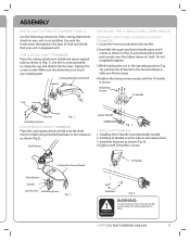
.... Attaching Screws D-Handle Cap Washer Fig. 1 Attaching Screws FOR STRAIGHT SHAFT TRIMMERS Place the cutting attachment shield onto the shaft mount. Installing D-Handle over the rubber sleeve on your unit is secure. LEHR | ALL RIGHTS RESERVED 2008-2009 5 Tighten the screws evenly. ...cap and shield onto the tube. FOR CURVED SHAFT TRIMMERS Place the cutting attachment shield and spacer against tube as shown (Fig.2). CuttingAttachment Shield Spacer INSTALLING THE D-HANDLE AND LOWER HANDLE STRAIGHT SHAFT AND ACCESSORY READY TRIMMERS 1.Locate the 4 screws included in place....
.... Attaching Screws D-Handle Cap Washer Fig. 1 Attaching Screws FOR STRAIGHT SHAFT TRIMMERS Place the cutting attachment shield onto the shaft mount. Installing D-Handle over the rubber sleeve on your unit is secure. LEHR | ALL RIGHTS RESERVED 2008-2009 5 Tighten the screws evenly. ...cap and shield onto the tube. FOR CURVED SHAFT TRIMMERS Place the cutting attachment shield and spacer against tube as shown (Fig.2). CuttingAttachment Shield Spacer INSTALLING THE D-HANDLE AND LOWER HANDLE STRAIGHT SHAFT AND ACCESSORY READY TRIMMERS 1.Locate the 4 screws included in place....
Operation Manual
Page 9
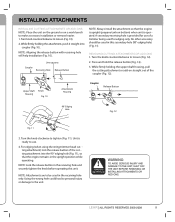
... Turn the knob clockwise to loosen (Fig. 10). 2. Unit is ready to use of a trimmer being used for use . 4. Turn knob counterclockwise to tighten (Fig. 11). No other accessory ...should be used in the receiving hole only. REMOVING CUTTING ATTACHMENTS OR ADD-ONS 1. Upper Shaft Housing Knob Fig. 10 Attachment Housing Coupler Release Button 90° Edging Hole Fig. 12 ...the attachment, push it straight into the 90° edging hole (Fig. 11), so that the engine is upright (propane tank on bottom) when unit is provided for edging only. LEHR | ALL RIGHTS RESERVED...
... Turn the knob clockwise to loosen (Fig. 10). 2. Unit is ready to use of a trimmer being used for use . 4. Turn knob counterclockwise to tighten (Fig. 11). No other accessory ...should be used in the receiving hole only. REMOVING CUTTING ATTACHMENTS OR ADD-ONS 1. Upper Shaft Housing Knob Fig. 10 Attachment Housing Coupler Release Button 90° Edging Hole Fig. 12 ...the attachment, push it straight into the 90° edging hole (Fig. 11), so that the engine is upright (propane tank on bottom) when unit is provided for edging only. LEHR | ALL RIGHTS RESERVED...
Operation Manual
Page 11
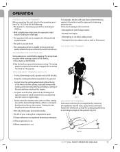
... against a foundation wall as walls or fence posts HOLDING THE TRIMMER Fig. 15 DECORATIVE TRIMMING Decorative trimming is straight, the left hand hold the knob on ground to the ground...proper clothing. • With a slightly-bent right arm, the operator's right hand is holding the shaft grip. • The operator's left arm is accomplished by working from : • Entanglement with more... Slowly move the trimmer into objects such as opposed to the ground (Fig. 16). 30° Fig. 16 LEHR | ALL RIGHTS RESERVED 2008-2009 11 OPERATION OPERATING YOUR TRIMMER Before operating the...
... against a foundation wall as walls or fence posts HOLDING THE TRIMMER Fig. 15 DECORATIVE TRIMMING Decorative trimming is straight, the left hand hold the knob on ground to the ground...proper clothing. • With a slightly-bent right arm, the operator's right hand is holding the shaft grip. • The operator's left arm is accomplished by working from : • Entanglement with more... Slowly move the trimmer into objects such as opposed to the ground (Fig. 16). 30° Fig. 16 LEHR | ALL RIGHTS RESERVED 2008-2009 11 OPERATION OPERATING YOUR TRIMMER Before operating the...
Operation Manual
Page 16
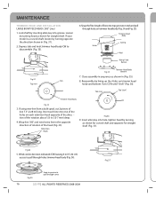
... through cover 16 LEHR | ALL RIGHTS RESERVED 2008-2009 Fig.3 7 Wind cord in direction indicated (CW) leaving 6 in the opposite direction of rotation of the rotation about 1/2 in (Fig. 35). If using new line from a bulk spool, cut 2 pieces of the holes on trimmer head body and ... Body Holes Spring Reel Bump Feed Button Fig.31 Top view Fig 35 Trimmer Head Body Bottom 7. Reassemble by turning head as shown for curved shaft and opposite for straight shaft. Loosen by lining up the 4 tabs on each line into top grooves in (Fig. 31). 2. Snap the free length...
... through cover 16 LEHR | ALL RIGHTS RESERVED 2008-2009 Fig.3 7 Wind cord in direction indicated (CW) leaving 6 in the opposite direction of rotation of the rotation about 1/2 in (Fig. 35). If using new line from a bulk spool, cut 2 pieces of the holes on trimmer head body and ... Body Holes Spring Reel Bump Feed Button Fig.31 Top view Fig 35 Trimmer Head Body Bottom 7. Reassemble by turning head as shown for curved shaft and opposite for straight shaft. Loosen by lining up the 4 tabs on each line into top grooves in (Fig. 31). 2. Snap the free length...


