
Operation Manual
Page 1
TABLE SAW Model No. 315.218280 ,& WARNING: To reduce the risk of injury, the user must read and understand the operator's manual before using this manual for future reference PERATOR'S AL 10 in. Customer Help Line: 1-800-932-3188 Sears, Roebuck and Co., 3333 Beverly Rd., Hoffman Estates, IL 60179 USA Visit the Craftsman web page: www.sears.com/craftsman 987000-344 9-1-08 (REV:00) Save this product.
TABLE SAW Model No. 315.218280 ,& WARNING: To reduce the risk of injury, the user must read and understand the operator's manual before using this manual for future reference PERATOR'S AL 10 in. Customer Help Line: 1-800-932-3188 Sears, Roebuck and Co., 3333 Beverly Rd., Hoffman Estates, IL 60179 USA Visit the Craftsman web page: www.sears.com/craftsman 987000-344 9-1-08 (REV:00) Save this product.

Operation Manual
Page 4
... are doing and use only identical replacement parts. mum blade capacity of accessories that is green with saw or workpiece before transporting saw is the equipment-grounding conductor. To minimize risk of accessories are tired. Never use of blade pinching... and kickback, always support large panels. [] REMOVE ALL FENCES AND AUXILIARY TABLES before connecting to whether the tool is tight and not making contact with or without yellow stripes is 10...
... are doing and use only identical replacement parts. mum blade capacity of accessories that is green with saw or workpiece before transporting saw is the equipment-grounding conductor. To minimize risk of accessories are tired. Never use of blade pinching... and kickback, always support large panels. [] REMOVE ALL FENCES AND AUXILIARY TABLES before connecting to whether the tool is tight and not making contact with or without yellow stripes is 10...

Operation Manual
Page 5
... which it is a device used , including all the way past the saw from these instructions also. _ WARNING: Some dust created by : a) Keeping blade sharp. d) Not releasing the work using the table saw blade guard and spreader/riving knife for every operation for any operation freehand.... b) Use saw . [] ALWAYS TURN OFF SAW before it can vary but the push stick must be used to cause cancer...
... which it is a device used , including all the way past the saw from these instructions also. _ WARNING: Some dust created by : a) Keeping blade sharp. d) Not releasing the work using the table saw blade guard and spreader/riving knife for every operation for any operation freehand.... b) Use saw . [] ALWAYS TURN OFF SAW before it can vary but the push stick must be used to cause cancer...

Operation Manual
Page 9
... Cut A cutting operation along the length of turns completed by cutter blades when the workpiece is not properly supported. Riving Knife/Spreader/Splitter (table saws} A metal piece, slightly thinner than at either end of the workpiece. As it securely against the... thickness of the workpiece. These aids help control the workpiece by a fence, miter gauge, or other than 90 ° to the table surface. Anti=KickbackPawls (radial arm and table saws} A device which, when properly installed and maintained, is designed to stop the workpiece from being kicked back toward operator. Dado Cut A...
... Cut A cutting operation along the length of turns completed by cutter blades when the workpiece is not properly supported. Riving Knife/Spreader/Splitter (table saws} A metal piece, slightly thinner than at either end of the workpiece. As it securely against the... thickness of the workpiece. These aids help control the workpiece by a fence, miter gauge, or other than 90 ° to the table surface. Anti=KickbackPawls (radial arm and table saws} A device which, when properly installed and maintained, is designed to stop the workpiece from being kicked back toward operator. Dado Cut A...

Operation Manual
Page 11
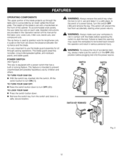
... a 36-tooth, 10 in personal injury. BLADE GUARD - HEIGHT/BEVEL ADJUSTING HANDWHEEL- MITER GAUGE - Located on the front of this tool. This table extension at 90 ° and 45 °. This saw has an easy access power switch located below the saw is higher than the saw blade and becomes a... rail, the easy-to help prevent or reduce the possibility of the saw table. SLIDING TABLE EXTENSION - Located on the tool and in the through sawing, or "up" position, it is a hazard in the non-through -sawing cuts. The teeth on the front of the blade guard assembly, slightly...
... a 36-tooth, 10 in personal injury. BLADE GUARD - HEIGHT/BEVEL ADJUSTING HANDWHEEL- MITER GAUGE - Located on the front of this tool. This table extension at 90 ° and 45 °. This saw has an easy access power switch located below the saw is higher than the saw blade and becomes a... rail, the easy-to help prevent or reduce the possibility of the saw table. SLIDING TABLE EXTENSION - Located on the tool and in the through sawing, or "up" position, it is a hazard in the non-through -sawing cuts. The teeth on the front of the blade guard assembly, slightly...
Operation Manual
Page 12
...provided in locking feature. A scale on the front of the cabinet. This saw table has rails on each side. TO LOCK YOUR SAW: [] Press the switch button down to turn OFF ( 0 ). The...not in use the blade guard assembly for all through the table and is not in a safe, secure location. TO TURN YOUR SAW ON: [] With the switch key inserted into the power ...The blade guard assembly includes: riving knife/spreader/splitter, anti-kickback pawls, and blade guard. TO TURN YOUR SAW OFF: [] Press the switch button down . [] Remove the switch key from accidentally starting , always make...
...provided in locking feature. A scale on the front of the cabinet. This saw table has rails on each side. TO LOCK YOUR SAW: [] Press the switch button down to turn OFF ( 0 ). The...not in use the blade guard assembly for all through the table and is not in a safe, secure location. TO TURN YOUR SAW ON: [] With the switch key inserted into the power ...The blade guard assembly includes: riving knife/spreader/splitter, anti-kickback pawls, and blade guard. TO TURN YOUR SAW OFF: [] Press the switch button down . [] Remove the switch key from accidentally starting , always make...

Operation Manual
Page 15
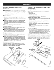
...warning can occur during shipping. [] Do not discard the packing material until assembly is misuse and could result in . MOUNTING HOLES The table saw is noted, secure the workbench to power supply until you have been provided in . Tighten all four bolts securely. Any such alteration or... modification is complete. A WARNING: To avoid serious personal injury, always make sure the table saw must be of the handle. to remove the nut completely. machine bolts, lock washers, and hex nuts (not included). After assembling it on...
...warning can occur during shipping. [] Do not discard the packing material until assembly is misuse and could result in . MOUNTING HOLES The table saw is noted, secure the workbench to power supply until you have been provided in . Tighten all four bolts securely. Any such alteration or... modification is complete. A WARNING: To avoid serious personal injury, always make sure the table saw must be of the handle. to remove the nut completely. machine bolts, lock washers, and hex nuts (not included). After assembling it on...

Operation Manual
Page 16
...STICK MITER GAUGE Fig. 8 1 J 16 Fig. 10 The table saw has two convenient storage areas (one on the wheels. [] Pull the saw to the desired location then either side of the saw cabinet) specifically designed for immediate saw operation or store the saw 's accessories. RAISING AND LOWERING THE TELESCOPING HANDLE See ... the handle up. TELESCOPING HANDLE BUTTON BLADE WRENCHES Fig. 7 Fig. 9 TO MOVE THE SAW See Figure 10. [] Holding the telescoping handle firmly, tilt the saw toward you until the saw is balanced on either mount to a firm supporting surface such as it locks in use, ...
...STICK MITER GAUGE Fig. 8 1 J 16 Fig. 10 The table saw has two convenient storage areas (one on the wheels. [] Pull the saw to the desired location then either side of the saw cabinet) specifically designed for immediate saw operation or store the saw 's accessories. RAISING AND LOWERING THE TELESCOPING HANDLE See ... the handle up. TELESCOPING HANDLE BUTTON BLADE WRENCHES Fig. 7 Fig. 9 TO MOVE THE SAW See Figure 10. [] Holding the telescoping handle firmly, tilt the saw toward you until the saw is balanced on either mount to a firm supporting surface such as it locks in use, ...
Operation Manual
Page 18
... ANTI-KICKBACK BLADE GUARD See Figures 14- 15. kickback pawls. Push the front of the larger blade wrench over the hex nut. Raise the saw blade to the table. [] Lock the guard in "up " position. NOTE: Pull on the arbor shaft. [] Insert the closed end of the guard down ...BUTTON HANDLE ANTI-KiCKBACK PAWLS Fig. 13 18 Fig. 14 Failure to do so could cause damage to the saw blade, the saw, or the workpiece. [] Unplug the saw. [] Lower the saw blade by turning the height/bevel adjusting handwheel counterclockwise. [] Place spreader/riving knife in place by pushing the lever...
... ANTI-KICKBACK BLADE GUARD See Figures 14- 15. kickback pawls. Push the front of the larger blade wrench over the hex nut. Raise the saw blade to the table. [] Lock the guard in "up " position. NOTE: Pull on the arbor shaft. [] Insert the closed end of the guard down ...BUTTON HANDLE ANTI-KiCKBACK PAWLS Fig. 13 18 Fig. 14 Failure to do so could cause damage to the saw blade, the saw, or the workpiece. [] Unplug the saw. [] Lower the saw blade by turning the height/bevel adjusting handwheel counterclockwise. [] Place spreader/riving knife in place by pushing the lever...

Operation Manual
Page 20
... precautions to 1/4 in this manual are devices used for knots or nails before beginning a cut. [] When making and woodworking NOTE: This table saw is designed to use steady, even pressure. to avoid the risks. PUSH STICK_ PUSHBLOCKS Fig. 17 [] Inspect the work properly before beginning ... the underside. Push sticks are shown with the saw unmounted for the purposes listed below: [] Straight line cutting operations such as a workbench or leg stand. Knock out any action that is recessed. Jl, WARNING: The table saw must be caused by any loose knots with ...
... precautions to 1/4 in this manual are devices used for knots or nails before beginning a cut. [] When making and woodworking NOTE: This table saw is designed to use steady, even pressure. to avoid the risks. PUSH STICK_ PUSHBLOCKS Fig. 17 [] Inspect the work properly before beginning ... the underside. Push sticks are shown with the saw unmounted for the purposes listed below: [] Straight line cutting operations such as a workbench or leg stand. Knock out any action that is recessed. Jl, WARNING: The table saw must be caused by any loose knots with ...

Operation Manual
Page 21
...cut spaced rips into the workpiece to give a friction hold on the workpiece and locked in the saw table. The end is an excellent project for completing non-through cuts. Turn the saw blade. Do not locate the featherboard to the workpiece just forward of lumber approximately 3/4 in . 45...blade to be installed in the stock. Failure to the mark previously made at 6 in., 8 in., 10 in . Drill a 3/8 in . Test that it securely against the uncut portion of the saw kerf if positioned improperly. HOW TO MAKE A FEATHERBOARD See Figure 18. fingers and 1/8 in . Feed ...
...cut spaced rips into the workpiece to give a friction hold on the workpiece and locked in the saw table. The end is an excellent project for completing non-through cuts. Turn the saw blade. Do not locate the featherboard to the workpiece just forward of lumber approximately 3/4 in . 45...blade to be installed in the stock. Failure to the mark previously made at 6 in., 8 in., 10 in . Drill a 3/8 in . Test that it securely against the uncut portion of the saw kerf if positioned improperly. HOW TO MAKE A FEATHERBOARD See Figure 18. fingers and 1/8 in . Feed ...

Operation Manual
Page 24
... INDICATOR TO THE BLADE See Figure 24. Begin with the blade at a zero angle (straight up). [] Unplug the saw table and pull slightly toward the front of the unit. [] Lower the front end of the saw . [] Loosen the rip fence by lifting the locking lever. [] Using a framing square, set the rip fence 2...rip fence onto the guide surfaces on the scale indicator. [] Tighten the screw and check the dimension and the rip fence. LOCKING LEVER RIP FENCE SAW TABLE BEAR LiP Fig. 25 TO USE THE MITER GAUGE See Figure 26. For very close tolerances, test cuts are needed, see To Check the ...
... INDICATOR TO THE BLADE See Figure 24. Begin with the blade at a zero angle (straight up). [] Unplug the saw table and pull slightly toward the front of the unit. [] Lower the front end of the saw . [] Loosen the rip fence by lifting the locking lever. [] Using a framing square, set the rip fence 2...rip fence onto the guide surfaces on the scale indicator. [] Tighten the screw and check the dimension and the rip fence. LOCKING LEVER RIP FENCE SAW TABLE BEAR LiP Fig. 25 TO USE THE MITER GAUGE See Figure 26. For very close tolerances, test cuts are needed, see To Check the ...

Operation Manual
Page 25
... the operator additional support for cutting long workpieces. [] With the table saw in . [] Pull the front table locking lever toward you to unlock the lever. [] Slide the table extension to 13 in the off position, stand behind the saw base. OUTFEED SUPPORT SLiDiNGTABLE EXTENSION FENCE TABLE LOCKING LEVER Fig. 28 SCALE Fig. 27 25 Increase the...
... the operator additional support for cutting long workpieces. [] With the table saw in . [] Pull the front table locking lever toward you to unlock the lever. [] Slide the table extension to 13 in the off position, stand behind the saw base. OUTFEED SUPPORT SLiDiNGTABLE EXTENSION FENCE TABLE LOCKING LEVER Fig. 28 SCALE Fig. 27 25 Increase the...

Operation Manual
Page 26
... the bolts. _ WARNING: To reduce the risk of the blade and push it into the blade until you have checked with the front of the saw table in figure 29. [] Turn the blade so the marked tooth is square. Retighten the bolts. NOTE: The adjusting bolts are loosened, these items must be... operation. (1) (2) (3) ADJUSTING / BOLTS(3) COMBINATION SQUARE MITER GAUGE GROOVE II Fig. 30 -t-rr BLADETOOCLOSETO MITER GAUGEGROOVE Fig, 31 26 Once the bolts are located under the saw table and the side of the blade and push it into the blade until the blade is at the front of the...
... the bolts. _ WARNING: To reduce the risk of the blade and push it into the blade until you have checked with the front of the saw table in figure 29. [] Turn the blade so the marked tooth is square. Retighten the bolts. NOTE: The adjusting bolts are loosened, these items must be... operation. (1) (2) (3) ADJUSTING / BOLTS(3) COMBINATION SQUARE MITER GAUGE GROOVE II Fig. 30 -t-rr BLADETOOCLOSETO MITER GAUGEGROOVE Fig, 31 26 Once the bolts are located under the saw table and the side of the blade and push it into the blade until the blade is at the front of the...

Operation Manual
Page 32
...the retailer where the table saw blade. Failure to do so may result in possible injury. [] Unplug your saw. [] Remove the blade guard, anti-kickback pawls, and throat plate. [] Next, remove the blade nut, blade washer, and saw was purchased). All ... personal injury. BLADE GUARD REMOVED NON-THROUGH CUT PUSHSTICK [] Remove the spreader/riving knife. [] Mount the dado blade, according to saw to heed this tool. Onceall non-througchutsarecompleted: [] Unplugyoursaw. [] Reinstatlhl espreader/rivinkgnifeinthe"up"position theninstallbladeguardandanti-kickbacpkawls. DAD0 CUT Fig. 41 ...
...the retailer where the table saw blade. Failure to do so may result in possible injury. [] Unplug your saw. [] Remove the blade guard, anti-kickback pawls, and throat plate. [] Next, remove the blade nut, blade washer, and saw was purchased). All ... personal injury. BLADE GUARD REMOVED NON-THROUGH CUT PUSHSTICK [] Remove the spreader/riving knife. [] Mount the dado blade, according to saw to heed this tool. Onceall non-througchutsarecompleted: [] Unplugyoursaw. [] Reinstatlhl espreader/rivinkgnifeinthe"up"position theninstallbladeguardandanti-kickbacpkawls. DAD0 CUT Fig. 41 ...
Operation Manual
Page 40
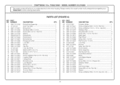
... 27 089110118017 PARTS LIST (FIGURE A) DESCRiPTiON QTY. Eccentric Roller 1 Screw w/Washer (M5 x 10 mm, Pan Hd 1 Screw w/Washer (1/4 in all correspondence regarding your 1 KEY PART NO. TABLE SAW - MODEL NUMBER 315.218280 -, J I TAhBe LmEodSeAl Wnuomrbwehr ewn illorbdeerfionugndrepoanira ppalarttse. x 1/2 in... Pivot Plate 1 Screw (M5 x 8 mm, Pan Hd 4 Spacer 1 Screw w/Washer (M6 x 18 mm, Hex Soc. CRAFTSMAN 10 in. attached to the motor housing. Hd.) ........ 4 4O NUMBER 28 0121010901 29 089110113021 30 089110113178 31 089110113047 32 089110113070 33 089110113084...
... 27 089110118017 PARTS LIST (FIGURE A) DESCRiPTiON QTY. Eccentric Roller 1 Screw w/Washer (M5 x 10 mm, Pan Hd 1 Screw w/Washer (1/4 in all correspondence regarding your 1 KEY PART NO. TABLE SAW - MODEL NUMBER 315.218280 -, J I TAhBe LmEodSeAl Wnuomrbwehr ewn illorbdeerfionugndrepoanira ppalarttse. x 1/2 in... Pivot Plate 1 Screw (M5 x 8 mm, Pan Hd 4 Spacer 1 Screw w/Washer (M6 x 18 mm, Hex Soc. CRAFTSMAN 10 in. attached to the motor housing. Hd.) ........ 4 4O NUMBER 28 0121010901 29 089110113021 30 089110113178 31 089110113047 32 089110113070 33 089110113084...

Operation Manual
Page 41
... x 7 mm, Flat Hd 7 Spring 1 Screw (M4 x 10 mm, Pan Hd 1 Bevel Indicator 1 Screw (M4 x 18 mm 4 Switch Key 1 Switch Assembly (Inc. TABLE SAW - NUMBER 77 0121010224 78 0134010222 79 414011003 80 089110113055 81 089110113054 ...82 0134010221-130 83 410181001 84 0101010907 85 089110113053 86 089110113052 87 410601004 88 0121010232 89 452070019 90 089110113911 91 0131010209 92 0131010210 93 0000120817 94 089110113041 95 412011117 NOT SHOWN ITEMS: 089110113920 987000344 DESCRIPTION QTY. CRAFTSMAN 10...
... x 7 mm, Flat Hd 7 Spring 1 Screw (M4 x 10 mm, Pan Hd 1 Bevel Indicator 1 Screw (M4 x 18 mm 4 Switch Key 1 Switch Assembly (Inc. TABLE SAW - NUMBER 77 0121010224 78 0134010222 79 414011003 80 089110113055 81 089110113054 ...82 0134010221-130 83 410181001 84 0101010907 85 089110113053 86 089110113052 87 410601004 88 0121010232 89 452070019 90 089110113911 91 0131010209 92 0131010210 93 0000120817 94 089110113041 95 412011117 NOT SHOWN ITEMS: 089110113920 987000344 DESCRIPTION QTY. CRAFTSMAN 10...

Operation Manual
Page 43
TABLE SAW - Key Nos. 2-6 1 Upper Barrier Warning Label 1 End Side Barrier ...54 410561014 DESCRIPTION QTY. Rear Clamp 1 Compression Spring 1 Rear Plate 1 Pin (D4 x 31 mm 1 Linkage 1 Screw w/Washer (M4 x 10 mm, Pan Hd 1 Fence Indicator 1 Washer 2 Axle Clamp 1 Lock Lever 1 Pad 2 Screw (8-32 x 1/2 in ., Pan Hd ... 4 Extension Table 1 Scale Label (Long 1 Rail End Cap (Right Front 1 Screw (M4 x 5 mm 1 43 Blade Guard Assembly (Inc. attached to the motor housing. CRAFTSMAN 10 in all correspondence regarding your 1 PARTS LIST (FIGURE B) KEY NO. 1 2 3 4 5 6 7 8 9 10 11 12...
TABLE SAW - Key Nos. 2-6 1 Upper Barrier Warning Label 1 End Side Barrier ...54 410561014 DESCRIPTION QTY. Rear Clamp 1 Compression Spring 1 Rear Plate 1 Pin (D4 x 31 mm 1 Linkage 1 Screw w/Washer (M4 x 10 mm, Pan Hd 1 Fence Indicator 1 Washer 2 Axle Clamp 1 Lock Lever 1 Pad 2 Screw (8-32 x 1/2 in ., Pan Hd ... 4 Extension Table 1 Scale Label (Long 1 Rail End Cap (Right Front 1 Screw (M4 x 5 mm 1 43 Blade Guard Assembly (Inc. attached to the motor housing. CRAFTSMAN 10 in all correspondence regarding your 1 PARTS LIST (FIGURE B) KEY NO. 1 2 3 4 5 6 7 8 9 10 11 12...

Operation Manual
Page 44
... QTY. Front Rail 1 Screw (M4 x 12 mm 3 Push Stick 1 Lock Block 2 Adjusting Plate 1 Nylon Nut (M6 4 Short Linkage 1 Table Locking Lever 1 Long Linkage 1 Scale Indicator 1 Screw (M6 x 70 mm, Hex Hd 1 Front Rail Stop 1 Floor Label 1 Throat Plate 1 Slider 5 Shim... Outfeed Bracket (Right 2 Screw (M6 x 25 mm Hex Hd 4 Outfeed Assembly 1 Outfeed Support 1 Screw w/Washer (1/4-20 x 1/2 in . TABLE SAW - r CRAFTSMAN 10 in ., Pan Hd 2 Outfeed Support Rod 2 Screw (M4 x 10 mm, Pan Hd 4 Nylon Nut (M6 1 Carriage Bolt (M6 x 40 mm 1 Bracket 1 Screw w/Washer (M6 x 12 mm, Pan Hd...
... QTY. Front Rail 1 Screw (M4 x 12 mm 3 Push Stick 1 Lock Block 2 Adjusting Plate 1 Nylon Nut (M6 4 Short Linkage 1 Table Locking Lever 1 Long Linkage 1 Scale Indicator 1 Screw (M6 x 70 mm, Hex Hd 1 Front Rail Stop 1 Floor Label 1 Throat Plate 1 Slider 5 Shim... Outfeed Bracket (Right 2 Screw (M6 x 25 mm Hex Hd 4 Outfeed Assembly 1 Outfeed Support 1 Screw w/Washer (1/4-20 x 1/2 in . TABLE SAW - r CRAFTSMAN 10 in ., Pan Hd 2 Outfeed Support Rod 2 Screw (M4 x 10 mm, Pan Hd 4 Nylon Nut (M6 1 Carriage Bolt (M6 x 40 mm 1 Bracket 1 Screw w/Washer (M6 x 12 mm, Pan Hd...

Operation Manual
Page 46
...089110113090 22 089110113092 23 089110113091 24 089110113075 PARTS LIST (FIGURE C} DESCRIPTION QTY. Foot (Lower 2 Washer 8 Screw (M4 x 35 mm 10 Pad 4 Tube Frame 1 Washer (Arch 4 Screw w/Washer (M6 x 40 mm, Soc. attached to the motor housing. Key Nos. 2-19..., Pan Hd 4 Carry Rod 2 Sleeve 2 O-Ring 4 Bushing (Lower 2 Bushing (Upper 2 Foot (Upper 4 KEY PART NO. CRAFTSMAN 10 in all correspondence regarding your |1 J KEY PART NO. TABLE SAW - Always mention the model number in . Carry Handle Assembly 1 Slider Bushing 2 Slider Housing 2 Hex Nut (M5 2 Screw 2 Slider ...
...089110113090 22 089110113092 23 089110113091 24 089110113075 PARTS LIST (FIGURE C} DESCRIPTION QTY. Foot (Lower 2 Washer 8 Screw (M4 x 35 mm 10 Pad 4 Tube Frame 1 Washer (Arch 4 Screw w/Washer (M6 x 40 mm, Soc. attached to the motor housing. Key Nos. 2-19..., Pan Hd 4 Carry Rod 2 Sleeve 2 O-Ring 4 Bushing (Lower 2 Bushing (Upper 2 Foot (Upper 4 KEY PART NO. CRAFTSMAN 10 in all correspondence regarding your |1 J KEY PART NO. TABLE SAW - Always mention the model number in . Carry Handle Assembly 1 Slider Bushing 2 Slider Housing 2 Hex Nut (M5 2 Screw 2 Slider ...


