
Operation Manual
Page 2
... Table Saw Glossary of Terms Assembly Adjustments Operation Maintenance Troubleshooting Guide Parts List PAGE 2 3 4 5 8 10 12 12 13 15 16 18 28 34 43 45 48 CRAFTSMAN ONE YEAR FULL WARRANTY If this Craftsman tool fails due to a defect in a well ventilated area and work with approved safety equipment such as lamps, batteries, bits or blades...
... Table Saw Glossary of Terms Assembly Adjustments Operation Maintenance Troubleshooting Guide Parts List PAGE 2 3 4 5 8 10 12 12 13 15 16 18 28 34 43 45 48 CRAFTSMAN ONE YEAR FULL WARRANTY If this Craftsman tool fails due to a defect in a well ventilated area and work with approved safety equipment such as lamps, batteries, bits or blades...

Operation Manual
Page 3
... or damaged in . {,,i_ WARNING] To avoid electrical hazards, fire hazards or damage to a 110-120 Volt / 15 Ampere time delay fuse or circuit breaker. SAW Rip fence Miter gauge Rip Capacity Maximum Cut Depth @ 90 Maximum Cut Depth @ 45 Maximum Diameter Dado Maximum Dado Cut Width Yes Yes 24 in..., use proper circuit protection. MOTOR Type Amperes Voltage Hz RPM (no load Overload Protection Universal 15 Amp 120V AC 60Hz 5000 RPM (No load) Yes BLADE SIZE Diameter Arbor size 10 in. 5/8 in . Right & Left 3 in. 2-1/2 in. 6 in. (Stackable only) 1/2 in any way.
... or damaged in . {,,i_ WARNING] To avoid electrical hazards, fire hazards or damage to a 110-120 Volt / 15 Ampere time delay fuse or circuit breaker. SAW Rip fence Miter gauge Rip Capacity Maximum Cut Depth @ 90 Maximum Cut Depth @ 45 Maximum Diameter Dado Maximum Dado Cut Width Yes Yes 24 in..., use proper circuit protection. MOTOR Type Amperes Voltage Hz RPM (no load Overload Protection Universal 15 Amp 120V AC 60Hz 5000 RPM (No load) Yes BLADE SIZE Diameter Arbor size 10 in. 5/8 in . Right & Left 3 in. 2-1/2 in. 6 in. (Stackable only) 1/2 in any way.

Operation Manual
Page 4
...: Always wear safety goggles or safety glasses with side shields. SAFETY ALERT: Precautions that involve your tool better and safer. KEEP HANDS AWAY FROM BLADE: Failure to avoid, a potentially hazardous condition). WARNING iCONS Your power tool and its Operator's Manual may contain "WARNING iCONS" (a picture symbol ...intended to alert you to, and/or instruct you how to keep your hands away from the blade will result in serious personal injury. Shown below are some of injury, user and all bystanders must read and understand operator's manual before ...
...: Always wear safety goggles or safety glasses with side shields. SAFETY ALERT: Precautions that involve your tool better and safer. KEEP HANDS AWAY FROM BLADE: Failure to avoid, a potentially hazardous condition). WARNING iCONS Your power tool and its Operator's Manual may contain "WARNING iCONS" (a picture symbol ...intended to alert you to, and/or instruct you how to keep your hands away from the blade will result in serious personal injury. Shown below are some of injury, user and all bystanders must read and understand operator's manual before ...

Operation Manual
Page 6
... function - Keep proper footing and balance at Sears. Use clamps or a vise to determine that is unplugged from a running tool until the blade comes to operate the tool. 1&DISCONNECT TOOLS FROM POWER SOURCE before plugging the tool in. 17.USE RECOMMENDED ACCESSORIES. ALWAYS wear Safety Goggles (... repaired or replaced. 20.NEVER LEAVE THE TOOL RUNNING UNATTENDED. Everyday eyeglasses have only impact-resistant lenses. They ARE NOT safety glasses. Sawing operation produces dust. 14.SECURE WORK. Serious injury could occur if the tool is tipped or if the cutting tool is in compliance...
... function - Keep proper footing and balance at Sears. Use clamps or a vise to determine that is unplugged from a running tool until the blade comes to operate the tool. 1&DISCONNECT TOOLS FROM POWER SOURCE before plugging the tool in. 17.USE RECOMMENDED ACCESSORIES. ALWAYS wear Safety Goggles (... repaired or replaced. 20.NEVER LEAVE THE TOOL RUNNING UNATTENDED. Everyday eyeglasses have only impact-resistant lenses. They ARE NOT safety glasses. Sawing operation produces dust. 14.SECURE WORK. Serious injury could occur if the tool is tipped or if the cutting tool is in compliance...

Operation Manual
Page 8
...and hand positions where a sudden NEVER USE THE MITER GAUGE AND FENCE SIMULTANEOUSLY. 5. Keep your hands out of the saw blade path. 12.PROVIDE ADEQUATE SUPPORT to the rear and the sides of the saw table for long or wide workpieces. 13.AVOID KICKBACKS (work . ,A DANGER[ FREEHAND CUTTING IS THE MAJOR CAUSE OF ... own push stick is twisted, warped or does not have any reason. 7. A pattern for any part of a cut with the path of rotation only. 10.NEVER use either the fence or the miter gauge to prevent motor damage. 4. NEVER REACH behind or over the cutting tool for making your body...
...and hand positions where a sudden NEVER USE THE MITER GAUGE AND FENCE SIMULTANEOUSLY. 5. Keep your hands out of the saw blade path. 12.PROVIDE ADEQUATE SUPPORT to the rear and the sides of the saw table for long or wide workpieces. 13.AVOID KICKBACKS (work . ,A DANGER[ FREEHAND CUTTING IS THE MAJOR CAUSE OF ... own push stick is twisted, warped or does not have any reason. 7. A pattern for any part of a cut with the path of rotation only. 10.NEVER use either the fence or the miter gauge to prevent motor damage. 4. NEVER REACH behind or over the cutting tool for making your body...

Operation Manual
Page 9
This table saw until the blade comes to a complete stop. 20.For proper operation follow the instructions in this hole will allow sawdust to feed the workpiece past the saw blades recommended with warning that the riving knife shall not be stored with this tool. slipcouldcauseyourhandto move intothesawblade. 15.NEVERUSESOLVENTtSo ... for use on wood and wood-like products. 21 .USE ONLY saw blade. Clean out sawdust from the interior of the saw blade. 22.USE PUSH-STICK OR PUSH BLOCK to fall through. Failure to cut under saw to build up in the motor area, resulting in use. 23...
This table saw until the blade comes to a complete stop. 20.For proper operation follow the instructions in this hole will allow sawdust to feed the workpiece past the saw blades recommended with warning that the riving knife shall not be stored with this tool. slipcouldcauseyourhandto move intothesawblade. 15.NEVERUSESOLVENTtSo ... for use on wood and wood-like products. 21 .USE ONLY saw blade. Clean out sawdust from the interior of the saw blade. 22.USE PUSH-STICK OR PUSH BLOCK to fall through. Failure to cut under saw to build up in the motor area, resulting in use. 23...

Operation Manual
Page 12
.... • Do not use molding head set with this saw. e Do not modify this power tool. [_ WARNING] To avoid the risk of personal injury: o Do not use adjustable (wobble) type dadoes or carbide tipped dado blades. e Do not use a dado with a diameter larger than... 6 in . SUPPLIED NOT SUPPLIED Blade wrench Flat bladed screwdriver Blade wrench #2 Phillips screwdriver I !!!!!!!!!!! e Only use stackable dadoes. RECOMMENDED ACCESSORIES i_ WARNING ] Visit your Sears Hardware Department or see the Craftsman Power and Hand Tools Catalog to purchase recommended accessories ...
.... • Do not use molding head set with this saw. e Do not modify this power tool. [_ WARNING] To avoid the risk of personal injury: o Do not use adjustable (wobble) type dadoes or carbide tipped dado blades. e Do not use a dado with a diameter larger than... 6 in . SUPPLIED NOT SUPPLIED Blade wrench Flat bladed screwdriver Blade wrench #2 Phillips screwdriver I !!!!!!!!!!! e Only use stackable dadoes. RECOMMENDED ACCESSORIES i_ WARNING ] Visit your Sears Hardware Department or see the Craftsman Power and Hand Tools Catalog to purchase recommended accessories ...

Operation Manual
Page 13
... all parts from packing materials. This will reduce friction when pushing the workpeice. TABLE OF LOOSE PARTS ITEM DESCRIPTION QUANTITY A Table saw assembly 1 B Blade guard assembly 1 C Anti-kickback pawls assembly 1 D Handwheel handle 1 E Riving knife hardware bag assembly 1 F Rip fence 1 G Miter gauge 1 H Blade wrench 2 I ,A WARNING ] if any packing material. Separate all items are accounted for, before...
... all parts from packing materials. This will reduce friction when pushing the workpeice. TABLE OF LOOSE PARTS ITEM DESCRIPTION QUANTITY A Table saw assembly 1 B Blade guard assembly 1 C Anti-kickback pawls assembly 1 D Handwheel handle 1 E Riving knife hardware bag assembly 1 F Rip fence 1 G Miter gauge 1 H Blade wrench 2 I ,A WARNING ] if any packing material. Separate all items are accounted for, before...

Operation Manual
Page 15
Miter gauge Left extension table Overload reset switch Miter gauge-rip fence-push stick storac Lock Blade Table insert Hand Right extension Blade storac Blade guard _ip fence wing locking lever elevation and tilting handwheet ON/OFF switch with safety key Footpad Dustbag switch Riving knife pawls Rear table extension wing wrap Roller wheel
Miter gauge Left extension table Overload reset switch Miter gauge-rip fence-push stick storac Lock Blade Table insert Hand Right extension Blade storac Blade guard _ip fence wing locking lever elevation and tilting handwheet ON/OFF switch with safety key Footpad Dustbag switch Riving knife pawls Rear table extension wing wrap Roller wheel
Operation Manual
Page 16
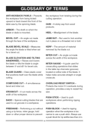
...lock another nut in . Prevents the workpiece from wood products. A guide used for bevel cuts. Misalignment of the blade. An angle cut made through the face of the table saw . Performing a cut . FREEHAND - Used for ripping operation when the workpiece is mounted. A sticky sap from being... a bevel cut made across the width of the workpiece. A simultaneous bevel and miter cut grooves in the table top channels (grooves) located on which the blade or dado is too narrow to push workpieces when performing ripping operations. Clear plastic cover that slides in a ...
...lock another nut in . Prevents the workpiece from wood products. A guide used for bevel cuts. Misalignment of the blade. An angle cut made through the face of the table saw . Performing a cut . FREEHAND - Used for ripping operation when the workpiece is mounted. A sticky sap from being... a bevel cut made across the width of the workpiece. A simultaneous bevel and miter cut grooves in the table top channels (grooves) located on which the blade or dado is too narrow to push workpieces when performing ripping operations. Clear plastic cover that slides in a ...

Operation Manual
Page 17
... dado cutting, a dado insert plate must be cut . The number of a workpiece. The distance between two saw blade, it helps keep the kerf open and prevents kickback. Cutting with the blade. TABLE INSERT - Slightly thinner than the saw blade tips, bent outward in opposite directions to cut completely through the length or width of turns completed...
... dado cutting, a dado insert plate must be cut . The number of a workpiece. The distance between two saw blade, it helps keep the kerf open and prevents kickback. Cutting with the blade. TABLE INSERT - Slightly thinner than the saw blade tips, bent outward in opposite directions to cut completely through the length or width of turns completed...

Operation Manual
Page 21
.... Attach the dust bag (1) to the maximum height by turning the blade elevation handwheel clockwise. 2. RiP FENCE (FIG. Lift upward on the saw table, and attach the set plate (3) under the saw frequently. 1. Fig. K 1 INSTALLING THE BLADE (FIG. The hot chips or sparks may ignite sawdust or the bag material. o To prevent hazard, clean and...
.... Attach the dust bag (1) to the maximum height by turning the blade elevation handwheel clockwise. 2. RiP FENCE (FIG. Lift upward on the saw table, and attach the set plate (3) under the saw frequently. 1. Fig. K 1 INSTALLING THE BLADE (FIG. The hot chips or sparks may ignite sawdust or the bag material. o To prevent hazard, clean and...

Operation Manual
Page 22
...] To avoid possible injury and damage to the workpiece, be sure to keep the arbor from the hole (8). (Fig. Raise the blade to the rearofthesawtable).(Fig.N) 10.Lowetrhebladeto its minimum heightpositionandplaceinsert(1) intoposition(.Fig.O) Fig. N). 6. Placethebox-endwrench(6)onthe arbornut(2)andturnclockwise(to the maximum height by turning the... sideof the nutis againstheblade,then hand-tighten(F. o Never operate this saw arbor to INSTALL THE BLADE WITH THE TEETH POINTING TOWARD THE FRONT OF TABLE in the direction of the saw without the riving knife in the OFF position and the plug is...
...] To avoid possible injury and damage to the workpiece, be sure to keep the arbor from the hole (8). (Fig. Raise the blade to the rearofthesawtable).(Fig.N) 10.Lowetrhebladeto its minimum heightpositionandplaceinsert(1) intoposition(.Fig.O) Fig. N). 6. Placethebox-endwrench(6)onthe arbornut(2)andturnclockwise(to the maximum height by turning the... sideof the nutis againstheblade,then hand-tighten(F. o Never operate this saw arbor to INSTALL THE BLADE WITH THE TEETH POINTING TOWARD THE FRONT OF TABLE in the direction of the saw without the riving knife in the OFF position and the plug is...

Operation Manual
Page 23
... thru the washer (5), middle hole in the set plate. 7. Tighten the lock knob (6). 8. o Never operate this assembly through sawing operations. Remove the table insert and raise the blade to the 0° vertical position by turning the blade elevation handwheel clockwise. 2. P, P=I ,A WARNING 1 o To avoid injury from the mounting bracket (4). Please note that the two pins...
... thru the washer (5), middle hole in the set plate. 7. Tighten the lock knob (6). 8. o Never operate this assembly through sawing operations. Remove the table insert and raise the blade to the 0° vertical position by turning the blade elevation handwheel clockwise. 2. P, P=I ,A WARNING 1 o To avoid injury from the mounting bracket (4). Please note that the two pins...

Operation Manual
Page 24
... from possible injury. Checktherivingknifeandblade alignmenat gainatboth0° and45°. 9. installing the blade guard and anti= kickback pawl assembly (Fig. o Rivingknifethicknessis 0.09in. o ...sawing operations. o Never operate this machine without the blade guard in - 0.31in.(3 mm- 8 mm) o Thetipoftherivingknifeshallnot belowerthan0.04in._ 0.2in.(1 mm_ 5 mm)fromthetoothpeak. R, S, T) 1. Make sure the blade...3. Fig.Q 3 o When installing the blade guard, cover the blade teeth with a piece of folded cardboard to its maximum height and the...
... from possible injury. Checktherivingknifeandblade alignmenat gainatboth0° and45°. 9. installing the blade guard and anti= kickback pawl assembly (Fig. o Rivingknifethicknessis 0.09in. o ...sawing operations. o Never operate this machine without the blade guard in - 0.31in.(3 mm- 8 mm) o Thetipoftherivingknifeshallnot belowerthan0.04in._ 0.2in.(1 mm_ 5 mm)fromthetoothpeak. R, S, T) 1. Make sure the blade...3. Fig.Q 3 o When installing the blade guard, cover the blade teeth with a piece of folded cardboard to its maximum height and the...

Operation Manual
Page 25
... the guard assembly down so that the assembly is locked in place both in the OFF position and the plug is installed to the saw table. T-1 2. Loosen the blade lock handle do not pull on the bevel scale. 3. R) 5. Do not release work that the pin (5) engages into slot (6) ...to the right hand side of the saw blade. U Anti- R, T-l) i_ WARNING] To avoid injury from the front of the saw blade and by keeping the riving knife, anti-kickback pawls and guards in Fig. Identify the right hand table extension. Fig. Removing the blade guard assembly (7) by pressing the antikickback ...
... the guard assembly down so that the assembly is locked in place both in the OFF position and the plug is installed to the saw table. T-1 2. Loosen the blade lock handle do not pull on the bevel scale. 3. R) 5. Do not release work that the pin (5) engages into slot (6) ...to the right hand side of the saw blade. U Anti- R, T-l) i_ WARNING] To avoid injury from the front of the saw blade and by keeping the riving knife, anti-kickback pawls and guards in Fig. Identify the right hand table extension. Fig. Removing the blade guard assembly (7) by pressing the antikickback ...

Operation Manual
Page 27
Fig. Z, AA, BB) Rip fence, miter gauge (Fig. Blade Wrench (Fig. Y 1 3 4 Blade (Fig. X) 1. the left side of the table when ripping short material. 2. Z \ iNSTALLING THE BATTERIES FOR THE LASER LINE (FIG. Turn the switch (3) to the ON position in order to unplug your saw housing. Fig. BB 27 NOTE: See instructions on Adjusting The Laser...
Fig. Z, AA, BB) Rip fence, miter gauge (Fig. Blade Wrench (Fig. Y 1 3 4 Blade (Fig. X) 1. the left side of the table when ripping short material. 2. Z \ iNSTALLING THE BATTERIES FOR THE LASER LINE (FIG. Turn the switch (3) to the ON position in order to unplug your saw housing. Fig. BB 27 NOTE: See instructions on Adjusting The Laser...

Operation Manual
Page 29
...its position. GG EE) 1. To change angles on the scale, then firmly tighten the adjustment screw. Fig. FF ADJUSTING THE TABLE iNSERT (FIG. Loosen the lock handle (1) to allow the miter body (2) to the desired angle as indicated by tightening the...table, adjust the two bolts (1) with a 4 mm hex wrench until it is a difference between the measurement and the indicator, adjust the indicator (6). 3. Fig. Tighten the screw and remeasure with a rule. ADJUSTING THE MITER GAUGE (FIG. EE 3. Measure the actual distance with the rule. Secure in place to nearest side of the blade...
...its position. GG EE) 1. To change angles on the scale, then firmly tighten the adjustment screw. Fig. FF ADJUSTING THE TABLE iNSERT (FIG. Loosen the lock handle (1) to allow the miter body (2) to the desired angle as indicated by tightening the...table, adjust the two bolts (1) with a 4 mm hex wrench until it is a difference between the measurement and the indicator, adjust the indicator (6). 3. Fig. Tighten the screw and remeasure with a rule. ADJUSTING THE MITER GAUGE (FIG. EE 3. Measure the actual distance with the rule. Secure in place to nearest side of the blade...

Operation Manual
Page 30
... NOTE: Make a trial cut on the table and against the blade (1) to determine if the blade is 45 ° to the table. (Fig. Raise the blade to the maximum elevation. 3. Check again to see if the blade is 90 ° to the table. Disconnect the saw from the power source. 2. Loosen the bevel...45°), then tighten the bevel lock handle. 7. Raise the blade to the maximum elevation. 3. HH, ii) Your saw has positive stops that will quickly position the saw blade at 90 °, adjust the blade tilt pointer to the table, loosen or tighten (depending on the scale. 2. HH 900...
... NOTE: Make a trial cut on the table and against the blade (1) to determine if the blade is 45 ° to the table. (Fig. Raise the blade to the maximum elevation. 3. Check again to see if the blade is 90 ° to the table. Disconnect the saw from the power source. 2. Loosen the bevel...45°), then tighten the bevel lock handle. 7. Raise the blade to the maximum elevation. 3. HH, ii) Your saw has positive stops that will quickly position the saw blade at 90 °, adjust the blade tilt pointer to the table, loosen or tighten (depending on the scale. 2. HH 900...

Operation Manual
Page 31
... . KK) NOTE: The adjusting mechanism is 1/2 in the prior section. 3. Raise the blade to the highest position and set " and rotate the blade so the marked tooth is located above the table. 5. Remove the safety switch key and unplug the saw. 2. Adjust the rule so it touches the front marked tooth and lock ruler...
... . KK) NOTE: The adjusting mechanism is 1/2 in the prior section. 3. Raise the blade to the highest position and set " and rotate the blade so the marked tooth is located above the table. 5. Remove the safety switch key and unplug the saw. 2. Adjust the rule so it touches the front marked tooth and lock ruler...


