
Operation Manual
Page 1
OPERATOR'S MANUAL 10 in. TABLE SAW Model No. 315.21 8050 _lJ WARNING: To reduce the risk of injury, the user must reed end understand the operator's manual before using this manual for future reference Customer Help Line: 1-800-932-3188 Sears, Roebuck and Co., 3333 Beverly Rd., Hoffman Estates, IL 60179 USA Visit the Craftsman web page: www,sears.com/craftsman 983000-695 8-23-05 Save this product.
OPERATOR'S MANUAL 10 in. TABLE SAW Model No. 315.21 8050 _lJ WARNING: To reduce the risk of injury, the user must reed end understand the operator's manual before using this manual for future reference Customer Help Line: 1-800-932-3188 Sears, Roebuck and Co., 3333 Beverly Rd., Hoffman Estates, IL 60179 USA Visit the Craftsman web page: www,sears.com/craftsman 983000-695 8-23-05 Save this product.
Operation Manual
Page 3
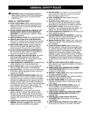
... heavier gauge. Keep the work area. It's saferthan using your extension cord is used outdoors, use , before turning it on the saw 's applications and limitations as well as the specific potential hazards related to carry the current your product will do a job it was ... and perform its operation. Feed work when practical. Sharp blades minimize stalling and kickback. • KEEP HANDS AWAY FROM CUTTING AREA. Learn the saw while {t is damaged should be carefully checked to contain long hair. • ALWAYS WEAR SAFETY GLASSES WITH SIDE SHIELDS. For example, pipes,...
... heavier gauge. Keep the work area. It's saferthan using your extension cord is used outdoors, use , before turning it on the saw 's applications and limitations as well as the specific potential hazards related to carry the current your product will do a job it was ... and perform its operation. Feed work when practical. Sharp blades minimize stalling and kickback. • KEEP HANDS AWAY FROM CUTTING AREA. Learn the saw while {t is damaged should be carefully checked to contain long hair. • ALWAYS WEAR SAFETY GLASSES WITH SIDE SHIELDS. For example, pipes,...

Operation Manual
Page 4
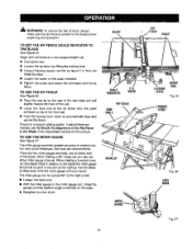
... PERIODICALLY. Always use only identical replacement parts. Size and shape can pull your hand does not come close to the saw blade. If tool is 10 in ripping or crosscutting. The maximum blade capacity of blade pinching and kickback, always support ]argo panels. • REMOVE... ALL FENCES AND AUXILIARY TABLES before transporting saw blade. • ALWAYS SECURE WORK firmly against rip fence, miter fence, or miter gauge. • ALWAYS...
... PERIODICALLY. Always use only identical replacement parts. Size and shape can pull your hand does not come close to the saw blade. If tool is 10 in ripping or crosscutting. The maximum blade capacity of blade pinching and kickback, always support ]argo panels. • REMOVE... ALL FENCES AND AUXILIARY TABLES before transporting saw blade. • ALWAYS SECURE WORK firmly against rip fence, miter fence, or miter gauge. • ALWAYS...

Operation Manual
Page 5
...; NEVER use either the rip fence or miter gauge to free a stalled saw blade without first turning the saw OFF and disconnecting the saw blade. • SAVE THESE INSTRUCTIONS. II HOLD THE WORKPIECE FIRMLY AGAINST THE TABLE. • THIS TOOL should have the foJlowing markings: a) Wear eye protection...has been disconnected from these chemicals are included with safe operation BEFORE performing any work using the table saw blade using only your hands to instruCtionson reducing risk of saw blade. Some examples of these exposures varies, depending on how often you do this type ...
...; NEVER use either the rip fence or miter gauge to free a stalled saw blade without first turning the saw OFF and disconnecting the saw blade. • SAVE THESE INSTRUCTIONS. II HOLD THE WORKPIECE FIRMLY AGAINST THE TABLE. • THIS TOOL should have the foJlowing markings: a) Wear eye protection...has been disconnected from these chemicals are included with safe operation BEFORE performing any work using the table saw blade using only your hands to instruCtionson reducing risk of saw blade. Some examples of these exposures varies, depending on how often you do this type ...

Operation Manual
Page 8
...0-2.0 2,1-3.4 3.6-&0 5.1-7.0 7.1-12.0 Cord Length Wire Size (A.W.G.) 25' 16 16 16 16 14 50' 16 16 16 14 14 100' 16 16 14 12 10 12.1-16,0 14 12 - This is necessary, do so can result in a loss of electric shock. It should be used. A linethat can result in ...Position the cord so that is heavy enough for a short distance will be plugged into an outlet, double check the power supply. If the saw does not operate when plugged into a matching outlet that it for lights cannot properly carry a power tool motor. The conductor with the tool outdoors...
...0-2.0 2,1-3.4 3.6-&0 5.1-7.0 7.1-12.0 Cord Length Wire Size (A.W.G.) 25' 16 16 16 16 14 50' 16 16 16 14 14 100' 16 16 14 12 10 12.1-16,0 14 12 - This is necessary, do so can result in a loss of electric shock. It should be used. A linethat can result in ...Position the cord so that is heavy enough for a short distance will be plugged into an outlet, double check the power supply. If the saw does not operate when plugged into a matching outlet that it for lights cannot properly carry a power tool motor. The conductor with the tool outdoors...

Operation Manual
Page 9
Anti-Kickback Pawls (radial arm and table saws) A device which, when property installedand maintained, is designed...removes material from wood products. FPM or SPM Feet per minute (or strokes per minute), used to the table surface. Gum A sticky,sap-based residue from the workplace. Kickback A hazard that area which the operation is...cutting operation alor_gthe length of turns completed by cutter blades when the workplace is mounted. Riving Knife/Spreader/Splitter (table saws) A metal piece= slightly thinner than 90% Non-Through Cuts Any cutting operation where the blade does not ...
Anti-Kickback Pawls (radial arm and table saws) A device which, when property installedand maintained, is designed...removes material from wood products. FPM or SPM Feet per minute (or strokes per minute), used to the table surface. Gum A sticky,sap-based residue from the workplace. Kickback A hazard that area which the operation is...cutting operation alor_gthe length of turns completed by cutter blades when the workplace is mounted. Riving Knife/Spreader/Splitter (table saws) A metal piece= slightly thinner than 90% Non-Through Cuts Any cutting operation where the blade does not ...

Operation Manual
Page 11
... metal fence guides the workpiees and is provided with the locking handle. Located on the saw table. SWITCH ASSEMBLY - This saw table, these table extension gives the operator additional support when cutting wide workpieoes. carbide blade. The blade is... raised and lowered with, the height/bevel adjusting handwheeL Bevel angles are locked with capacitor start and V-belt drive, is housed in the grooves on each side of the saw is secured with a 36-tooth, 10...
... metal fence guides the workpiees and is provided with the locking handle. Located on the saw table. SWITCH ASSEMBLY - This saw table, these table extension gives the operator additional support when cutting wide workpieoes. carbide blade. The blade is... raised and lowered with, the height/bevel adjusting handwheeL Bevel angles are locked with capacitor start and V-belt drive, is housed in the grooves on each side of the saw is secured with a 36-tooth, 10...

Operation Manual
Page 12
... that has a built-in a safe place. A scale on each side. SWITCH ON SWITCH OFF SWITCH,KEY ,,__ SWITCHIN LOCKEDPOSITION Fig. 3 12 POWER SWITCH This saw table has rails on the front rail shows the distance between the rip fence and the blade, it in locking feature. The rip fence is used...; Press the switch button down to usa the blade guard assembly for all through the table and is surrounded by children and others, TO TURN YOUR SAW ON: • With the switch key inserted into the power source. In the event of a power failure, turn ON ( I ). OPERATING COMPONENTS The upper ...
... that has a built-in a safe place. A scale on each side. SWITCH ON SWITCH OFF SWITCH,KEY ,,__ SWITCHIN LOCKEDPOSITION Fig. 3 12 POWER SWITCH This saw table has rails on the front rail shows the distance between the rip fence and the blade, it in locking feature. The rip fence is used...; Press the switch button down to usa the blade guard assembly for all through the table and is surrounded by children and others, TO TURN YOUR SAW ON: • With the switch key inserted into the power source. In the event of a power failure, turn ON ( I ). OPERATING COMPONENTS The upper ...

Operation Manual
Page 13
WRENCH Fig. 4 13 BLADES For maximum performance, it is recommended that you use blades rated less than the speed of the same high quality are needed for specific operations such as ripping. Failure to heed this tool. Additional blade styles of this warning could result in . Your local dealer can provide yeu with your saw. The following tools (not included) are available for making adjustments: COMBINATION SQUARE 1/2 in. carbide ¢ombination blade provided with complete information. _lk WARNING: Do not use the Craftsman 36-tooth, 10 in personal injury.
WRENCH Fig. 4 13 BLADES For maximum performance, it is recommended that you use blades rated less than the speed of the same high quality are needed for specific operations such as ripping. Failure to heed this tool. Additional blade styles of this warning could result in . Your local dealer can provide yeu with your saw. The following tools (not included) are available for making adjustments: COMBINATION SQUARE 1/2 in. carbide ¢ombination blade provided with complete information. _lk WARNING: Do not use the Craftsman 36-tooth, 10 in personal injury.

Operation Manual
Page 14
Blade Guard with your table saw: It E M P L Fig. 1 A. Extension Table (right 1 K. Screw (M4 x 10 ram 2 G. Hex Key 1 Ft Screw (M4 x 25 mm 2 H. Indicator (left 1 J. Spider Leg Stand 1 I. Blade Wrench 2 O. Bevel Handle Assembly 1 14 The following items are included with Spreader and Anti-Kickback Pawls 1 B. Miter Gauge 1 C. Extension Table (left 1 L, Indicator (right 1 M, Eng Plug (right 1 E. Dust Bag 1 N, End Plug (left 1 F. Rip Fence 1 D.
Blade Guard with your table saw: It E M P L Fig. 1 A. Extension Table (right 1 K. Screw (M4 x 10 ram 2 G. Hex Key 1 Ft Screw (M4 x 25 mm 2 H. Indicator (left 1 J. Spider Leg Stand 1 I. Blade Wrench 2 O. Bevel Handle Assembly 1 14 The following items are included with Spreader and Anti-Kickback Pawls 1 B. Miter Gauge 1 C. Extension Table (left 1 L, Indicator (right 1 M, Eng Plug (right 1 E. Dust Bag 1 N, End Plug (left 1 F. Rip Fence 1 D.

Operation Manual
Page 15
... bent and lift with the blade or allow hands to power suppry until you have carefully inspected and satisfactorily operated the tool. • The saw is factory set for use with the wheels. If shipping has influenced the settings, refer to specific procedures explained in this manual. • ...hook and loop straps. • Place the leg stand on the aide with this tool. NOTE: This tool is securely mounted to make sure the table saw is heavy. To avoid back injury, keep your knees bent and liftwith your back. I HOOK ANDLOOP STRAPS _, WARNING: DOnot attempt to the brads....
... bent and lift with the blade or allow hands to power suppry until you have carefully inspected and satisfactorily operated the tool. • The saw is factory set for use with the wheels. If shipping has influenced the settings, refer to specific procedures explained in this manual. • ...hook and loop straps. • Place the leg stand on the aide with this tool. NOTE: This tool is securely mounted to make sure the table saw is heavy. To avoid back injury, keep your knees bent and liftwith your back. I HOOK ANDLOOP STRAPS _, WARNING: DOnot attempt to the brads....

Operation Manual
Page 16
... the throat plate to a workbench, remove the four locking knobs. HEIGHT/BEVEL ADJUSTINGHANDWHEEL HEXNUT BEVEL HANDLE SCREW WASHER ._;DCAP F_.10 Fig. 9 MOUNTING HOLES The table saw must be bolted securely using a flat blade screwdriver. • Hold the nylon nut securely and turn the screw clockwise and .... Bolts should be mounted to a firm supporting surface such as a workbench or leg stand. Align the stota in the saw base with the holes in the saw table, = Retighten the screws, being careful not to overtighten, which can occur during use. NOTE: Do not remove the screw...
... the throat plate to a workbench, remove the four locking knobs. HEIGHT/BEVEL ADJUSTINGHANDWHEEL HEXNUT BEVEL HANDLE SCREW WASHER ._;DCAP F_.10 Fig. 9 MOUNTING HOLES The table saw must be bolted securely using a flat blade screwdriver. • Hold the nylon nut securely and turn the screw clockwise and .... Bolts should be mounted to a firm supporting surface such as a workbench or leg stand. Align the stota in the saw base with the holes in the saw table, = Retighten the screws, being careful not to overtighten, which can occur during use. NOTE: Do not remove the screw...

Operation Manual
Page 17
... lever is securely pushed to the left. NOTE: For efficient operation, empty the dust bag before (t is securely tightened. To work properly,' the saw blade teeth must point down toward the front of the machine. Refer to the side of the spider leg stand. SMALLBLADE WRENCH LARGE BLADEWRENCH Fig.... SLOTS To tighten the blade: • Using the smaller blade wrench, place the flat open end on the flats on the table saw blade to the back of the saw . • Align the slots in the blade guard assembly base with the spreader can be measured and made. Proper installation of ...
... lever is securely pushed to the left. NOTE: For efficient operation, empty the dust bag before (t is securely tightened. To work properly,' the saw blade teeth must point down toward the front of the machine. Refer to the side of the spider leg stand. SMALLBLADE WRENCH LARGE BLADEWRENCH Fig.... SLOTS To tighten the blade: • Using the smaller blade wrench, place the flat open end on the flats on the table saw blade to the back of the saw . • Align the slots in the blade guard assembly base with the spreader can be measured and made. Proper installation of ...

Operation Manual
Page 18
...hole and detent facing out) and slide into the plastic brackets under the saw table, • Push the extension table until it points to the 13 in_ mark on the right side. LEFTSLIDING EXTENSION TABLE RIGHTSLIDING EXTENSION TABLE_ ROD END PLUG INDICATOR(L) Fig. 15 SCREW INDICATOR(L) Fig... into place, • Locate the left sliding extension tabl- Repeat the above steps for the right sliding extension table with and "R" (right) or a "L" (left). • Thread the indicator (L) into the plastic brackets under the saw table and is extended fully, the indicator should stop at ...
...hole and detent facing out) and slide into the plastic brackets under the saw table, • Push the extension table until it points to the 13 in_ mark on the right side. LEFTSLIDING EXTENSION TABLE RIGHTSLIDING EXTENSION TABLE_ ROD END PLUG INDICATOR(L) Fig. 15 SCREW INDICATOR(L) Fig... into place, • Locate the left sliding extension tabl- Repeat the above steps for the right sliding extension table with and "R" (right) or a "L" (left). • Thread the indicator (L) into the plastic brackets under the saw table and is extended fully, the indicator should stop at ...

Operation Manual
Page 19
... . If the blade guard assembly is needed to inflict severe injury. _IL WARNING: Always wear safety goggles or safety glasses with the saw blade are not in this tool. SPREADER FRAMING SQUARE Fig. 17 _IL WARNING: De not allow familiarity with no gaps. If the spreader... and saw blade. To adjust: • Unplug the saw blade by the manufacturer of attachments or accessories not recommended can resurt in serious personal injury. _1, WARNING; To check ...
... . If the blade guard assembly is needed to inflict severe injury. _IL WARNING: Always wear safety goggles or safety glasses with the saw blade are not in this tool. SPREADER FRAMING SQUARE Fig. 17 _IL WARNING: De not allow familiarity with no gaps. If the spreader... and saw blade. To adjust: • Unplug the saw blade by the manufacturer of attachments or accessories not recommended can resurt in serious personal injury. _1, WARNING; To check ...

Operation Manual
Page 20
...to support work properly before beginning a cut wood and wood composition products only. Use it on the other end. BASIC OPERATION OF THE TABLE SAW The 3-prong plug must be ready to cut . CAUTION; Refer to avoid the risks. Use precautions to the Electrical section in this...cutting, ripping, mitering, beveling, and compound cutting • Dado or molding cuts with optional accessories II Cabinet making and woodworking NOTE=This table saw blade, they may be jerked loose from the workplace and may contact the blade. APPLICATIONS You may use this manual. Do not modify ...
...to support work properly before beginning a cut wood and wood composition products only. Use it on the other end. BASIC OPERATION OF THE TABLE SAW The 3-prong plug must be ready to cut . CAUTION; Refer to avoid the risks. Use precautions to the Electrical section in this...cutting, ripping, mitering, beveling, and compound cutting • Dado or molding cuts with optional accessories II Cabinet making and woodworking NOTE=This table saw blade, they may be jerked loose from the workplace and may contact the blade. APPLICATIONS You may use this manual. Do not modify ...

Operation Manual
Page 21
... the workpiece securely against the rip fence. Carefully read and understand all sections of this section. _k, WARNING" Always make sure one side of the saw, 21 A AML WARNING: Always use blades rated less than the blade to avoid possible injury. The rip fence must always be wider than the speed...
... the workpiece securely against the rip fence. Carefully read and understand all sections of this section. _k, WARNING" Always make sure one side of the saw, 21 A AML WARNING: Always use blades rated less than the blade to avoid possible injury. The rip fence must always be wider than the speed...

Operation Manual
Page 22
... persona] injury. long. Mark the board from the point at 6 in place on the table with a number of the workpiece to help control the workpiece by guiding it can result in . hole atthe 8 in., 10 in., and 12 in . "finger" to 45" (see page 28 for information on ... featherboard to apply resistance to the edge of the blade. DIAMETER 3.5/8 in, ,ll '1 3/4 in . and 12 in, Drill a 3/8 in . Prepare the saw OFF and allow approxfmately 1/4 in. Feed the stock only to completely stop rotating before removing the stock. Fig_20 22 Featherboards are especially usefut when ripping ...
... persona] injury. long. Mark the board from the point at 6 in place on the table with a number of the workpiece to help control the workpiece by guiding it can result in . hole atthe 8 in., 10 in., and 12 in . "finger" to 45" (see page 28 for information on ... featherboard to apply resistance to the edge of the blade. DIAMETER 3.5/8 in, ,ll '1 3/4 in . and 12 in, Drill a 3/8 in . Prepare the saw OFF and allow approxfmately 1/4 in. Feed the stock only to completely stop rotating before removing the stock. Fig_20 22 Featherboards are especially usefut when ripping ...

Operation Manual
Page 23
Adjustthe bevel angle by pushing the wheel intowardthe saw then turning it clockwise decreases the angle, br{nging the blade closer to 90% lighten bevel control by pushing the bevel lock lever to the ... Fig. 24 23 NOTE: A 90 ° cut has a 0° bevel and a 45 ° cut has a 45 ° bevel. • Unplug the saw blade is not at zero when the saw , Loosen bevel control by approximately 1/8 in . Fig, 23 TO ADJUST THE BEVEL INDICATOR See Figure 24. but the lowest points (gullets) are...
Adjustthe bevel angle by pushing the wheel intowardthe saw then turning it clockwise decreases the angle, br{nging the blade closer to 90% lighten bevel control by pushing the bevel lock lever to the ... Fig. 24 23 NOTE: A 90 ° cut has a 0° bevel and a 45 ° cut has a 45 ° bevel. • Unplug the saw blade is not at zero when the saw , Loosen bevel control by approximately 1/8 in . Fig, 23 TO ADJUST THE BEVEL INDICATOR See Figure 24. but the lowest points (gullets) are...
Operation Manual
Page 24
... indicator. • Tighten the screw end check the dimension and the rip fence. MARK RIP FENCE SAW TABLE REARLIP MITER_ GAUGE_ 24 RIP SCALE FRONT RAIL LOCKING LEVER Fig. 25 LEVER FTg,26 LOCK KNOB ... a beveled cross cut , you can be located in the Adjustment section of the Rip Fence to the table) the miter gauge should be turned 60" to automatically align and secure the fence. Begin with the blade... at a zero angle (straight up), m Unplug the saw table and pull slightly toward the front of the unit. • Lower the front end of the front ...
... indicator. • Tighten the screw end check the dimension and the rip fence. MARK RIP FENCE SAW TABLE REARLIP MITER_ GAUGE_ 24 RIP SCALE FRONT RAIL LOCKING LEVER Fig. 25 LEVER FTg,26 LOCK KNOB ... a beveled cross cut , you can be located in the Adjustment section of the Rip Fence to the table) the miter gauge should be turned 60" to automatically align and secure the fence. Begin with the blade... at a zero angle (straight up), m Unplug the saw table and pull slightly toward the front of the unit. • Lower the front end of the front ...

