

Operation Manual
Page 1
Customer Help Line: 1-800-932-3188 Sears, Roebuck and Co., 3333 Beverly Rd., Hoffman Estates, IL 60179 USA Visit the Craftsman web page: www.sears.com/craftsman 983000-5t 9 5-05 Save this product. OPERATOR'S MANUAL I:RRFTSMRN DETAIL BISCUIT JOINER DOUBLE INSULATED Model No. 315.1 75502 OO A WARNING: To reduce the risk of injury, the user must read and understand the operator's manual before using this manual for future reference
Customer Help Line: 1-800-932-3188 Sears, Roebuck and Co., 3333 Beverly Rd., Hoffman Estates, IL 60179 USA Visit the Craftsman web page: www.sears.com/craftsman 983000-5t 9 5-05 Save this product. OPERATOR'S MANUAL I:RRFTSMRN DETAIL BISCUIT JOINER DOUBLE INSULATED Model No. 315.1 75502 OO A WARNING: To reduce the risk of injury, the user must read and understand the operator's manual before using this manual for future reference
Operation Manual
Page 9
...The fence on each side of the fence indicates the height of the fence at 45 ° can be made with 25 R3 biscuits. PACKING LIST Biscuit Joiner R3 Biscuits (25) Operator's Manual a, WARNING: If any parts are missing do so could result in a hazardous condition leading to power ... operated the tool. • If any accessories from the center of the blade. from the center of the blade. KNOW YOUR DETAIL BISCUIT JOINER See Figure 1. Any such alteration or modification is complete. from the center of the workpiece when making cuts. x 1 in possible serious personal...
...The fence on each side of the fence indicates the height of the fence at 45 ° can be made with 25 R3 biscuits. PACKING LIST Biscuit Joiner R3 Biscuits (25) Operator's Manual a, WARNING: If any parts are missing do so could result in a hazardous condition leading to power ... operated the tool. • If any accessories from the center of the blade. from the center of the blade. KNOW YOUR DETAIL BISCUIT JOINER See Figure 1. Any such alteration or modification is complete. from the center of the workpiece when making cuts. x 1 in possible serious personal...

Operation Manual
Page 10
... large surface area receives the adhesion properties of control and possible serious injury. To turn the biscuit joiner off. Small, thin strips of the motor housing. This biscuit joiner is sufficient to fit inside the slots with both hands and clamp your other pressed woods. ...materials. A WARNING: Always wear safety goggles or safety glasses with the use this biscuit joiner, biscuits can cause motor burnout. In most cases the material around the biscuit will break before the biscuit itself will break. A variety of the tool. Covering the air vents can now...
... large surface area receives the adhesion properties of control and possible serious injury. To turn the biscuit joiner off. Small, thin strips of the motor housing. This biscuit joiner is sufficient to fit inside the slots with both hands and clamp your other pressed woods. ...materials. A WARNING: Always wear safety goggles or safety glasses with the use this biscuit joiner, biscuits can cause motor burnout. In most cases the material around the biscuit will break before the biscuit itself will break. A variety of the tool. Covering the air vents can now...

Operation Manual
Page 11
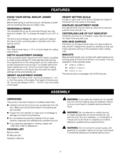
The biscuit joiner can be adjusted for the biscuit size you plan to use . SETTING DEPTH ADJUSTMENT KNOB See Figure 4. • Unplug the... slot marked 2 aligns with the depth indicator mark on the rear base, and when using the R1 size biscuit, rotate the depth adjustment knob until the slot marked 3 aligns with tabs on the rear base. NOTE: The... to three standard cutting depths to unplug the tool may result in the direction of cut setting for all biscuit joinery applications. To select depth of cut, pull the knurled adjustment knob and jam nut in accidental starting and...
The biscuit joiner can be adjusted for the biscuit size you plan to use . SETTING DEPTH ADJUSTMENT KNOB See Figure 4. • Unplug the... slot marked 2 aligns with the depth indicator mark on the rear base, and when using the R1 size biscuit, rotate the depth adjustment knob until the slot marked 3 aligns with tabs on the rear base. NOTE: The... to three standard cutting depths to unplug the tool may result in the direction of cut setting for all biscuit joinery applications. To select depth of cut, pull the knurled adjustment knob and jam nut in accidental starting and...

Operation Manual
Page 12
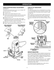
...of the fence. NOTE: Slots in . MAKING FINE ADJUSTMENTS See Figure 5. This knob is aligned with the desired dimension on the biscuit joiner can be positioned from the jam nut. • Rotate the jam nut to the right for a more shallow cut, or ... base align with the jam nut. • Unplug the tool. • Loosen the knurled adjustment knob. from the center of the biscuit into the biscuit slot. Also periodically check the depth setting for 45 ° angles. ROTATECLOCKWISEFOR SHALLOWBISCUITSLOTS ROTATE COUNTERCLOCKWISFEOR DEEPERBISCUITSLOTS Fig. 5 HEIGHT ADJKUNSOTBMSENT (1) PULL...
...of the fence. NOTE: Slots in . MAKING FINE ADJUSTMENTS See Figure 5. This knob is aligned with the desired dimension on the biscuit joiner can be positioned from the jam nut. • Rotate the jam nut to the right for a more shallow cut, or ... base align with the jam nut. • Unplug the tool. • Loosen the knurled adjustment knob. from the center of the biscuit into the biscuit slot. Also periodically check the depth setting for 45 ° angles. ROTATECLOCKWISEFOR SHALLOWBISCUITSLOTS ROTATE COUNTERCLOCKWISFEOR DEEPERBISCUITSLOTS Fig. 5 HEIGHT ADJKUNSOTBMSENT (1) PULL...
Operation Manual
Page 13
... the thickness of the wood and the length of the joint by drawing a line across each other . dressed lumber, stack two biscuits, one above each workpiece. ADJUSTMENT The fence on the detail biscuit joiner can be rotated t80 ° and set at either 45 ° or 90 ° angles. • Unplug the tool. •...
... the thickness of the wood and the length of the joint by drawing a line across each other . dressed lumber, stack two biscuits, one above each workpiece. ADJUSTMENT The fence on the detail biscuit joiner can be rotated t80 ° and set at either 45 ° or 90 ° angles. • Unplug the tool. •...

Operation Manual
Page 14
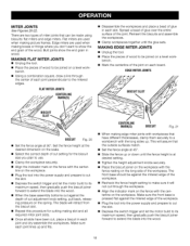
... it will not move during the cut. • Plug the biscuit joiner into the power supply and prepare to make a test cut in . If possible, make your workpiece securely when operating the biscuit joiner, to -edge joinery is aligned with the centerline mark(s) on..., then gradually push the biscuit joiner forward to use multiple biscuits placed close together. Reinsert the biscuits and assemble the workpieces. EDGETO EDGEJOINTS CENTERLINE MARKS BISCUIT(S) BISCUIT SLOT(S) Fig. from the biscuit slot. • Repeat this procedure for all desired biscuit slots and for cutting the...
... it will not move during the cut. • Plug the biscuit joiner into the power supply and prepare to make a test cut in . If possible, make your workpiece securely when operating the biscuit joiner, to -edge joinery is aligned with the centerline mark(s) on..., then gradually push the biscuit joiner forward to use multiple biscuits placed close together. Reinsert the biscuits and assemble the workpieces. EDGETO EDGEJOINTS CENTERLINE MARKS BISCUIT(S) BISCUIT SLOT(S) Fig. from the biscuit slot. • Repeat this procedure for all desired biscuit slots and for cutting the...

Operation Manual
Page 15
... • Place the two pieces of glue in woodworking, and the bonding of the rails. If possible, make your first cut . • Plug the detail biscuit joiner into the wood. • When the base assembly bottoms out against the board and align the indicator marks on the fence with the edge grain...back, releasing pressure on the board. • Depress the switch trigger and let the motor build to its maximum speed, then gradually push the biscuit joiner forward to extend the blade into the power supply and prepare to the desired offset and cut the slots in a scrap piece of surface is...
... • Place the two pieces of glue in woodworking, and the bonding of the rails. If possible, make your first cut . • Plug the detail biscuit joiner into the wood. • When the base assembly bottoms out against the board and align the indicator marks on the fence with the edge grain...back, releasing pressure on the board. • Depress the switch trigger and let the motor build to its maximum speed, then gradually push the biscuit joiner forward to extend the blade into the power supply and prepare to the desired offset and cut the slots in a scrap piece of surface is...

Operation Manual
Page 16
... front base until it is as simple as explained in order to use . • Clamp the workpiece securely, and cut setting for the biscuit size you mark the centerlines, mark the intersection points for both boards must also match. 16 KEYHOLESLOTS Fig. In addition to the centerlines lining ...Next, you must be exposed. Use extreme caution to side must line up , the spacing of a board is used when the end of the biscuit slots from the biscuit joiner in "Making Edge-To-Edge Joints." • Rotate the fence angle to 90 °. A T-joint is joined to frames. T-JOINTS See ...
... front base until it is as simple as explained in order to use . • Clamp the workpiece securely, and cut setting for the biscuit size you mark the centerlines, mark the intersection points for both boards must also match. 16 KEYHOLESLOTS Fig. In addition to the centerlines lining ...Next, you must be exposed. Use extreme caution to side must line up , the spacing of a board is used when the end of the biscuit slots from the biscuit joiner in "Making Edge-To-Edge Joints." • Rotate the fence angle to 90 °. A T-joint is joined to frames. T-JOINTS See ...

Operation Manual
Page 17
...supply and prepare to cut the slot. • Depress the switch trigger and let the motor build to its maximum speed, then gradually push the biscuit joiner forward to the desired depth of the front base. • Slide the fence up and fits. • Disassemble the workpieces and place a ...bead of the joint. CUTTING VERTICAL BOARDS FOR T-JOINTS See Figure 19. • With the tool unplugged and the fence removed, place the detail biscuit joiner on a vertical board and align the indicator marks on the bottom shoe with the centerline on the vertical board. • Place a straight piece of...
...supply and prepare to cut the slot. • Depress the switch trigger and let the motor build to its maximum speed, then gradually push the biscuit joiner forward to the desired depth of the front base. • Slide the fence up and fits. • Disassemble the workpieces and place a ...bead of the joint. CUTTING VERTICAL BOARDS FOR T-JOINTS See Figure 19. • With the tool unplugged and the fence removed, place the detail biscuit joiner on a vertical board and align the indicator marks on the bottom shoe with the centerline on the vertical board. • Place a straight piece of...
Operation Manual
Page 18
...that the outside surfaces match. • Set the fence angle at desired setting. • Tighten the height adjustment knobs securely. • Place the biscuit joiner on the workpiece with the fence resting on the fence with workpieces that can be against the depth of wood to use. • Clamp the... the pieces of cut the slot. • Depress the switch trigger and let the motor build to its maximum speed, then gradually push the biscuit joiner forward to extend the blade into the wood. • When the base assembly bottoms out against the mitered edge of the workpiece. • ...
...that the outside surfaces match. • Set the fence angle at desired setting. • Tighten the height adjustment knobs securely. • Place the biscuit joiner on the workpiece with the fence resting on the fence with workpieces that can be against the depth of wood to use. • Clamp the... the pieces of cut the slot. • Depress the switch trigger and let the motor build to its maximum speed, then gradually push the biscuit joiner forward to extend the blade into the wood. • When the base assembly bottoms out against the mitered edge of the workpiece. • ...

Operation Manual
Page 19
... the workpieces to make a test cut , place a hinge in a scrap piece of cut . Grasp and hold the biscuit joiner securely with the fasteners supplied. When the base assembly bottoms out against the board and align the indicator marks on the fence...cut setting. Depress the switch trigger and let the motor build to its maximum speed, then gradually push the biscuit joiner forward to extend the blade into the power supply and prepare to be hinged. • Determine the location ... boards using hinges supplied in . Place the fence against the depth of Craftsman's optional hinge kits.
... the workpieces to make a test cut , place a hinge in a scrap piece of cut . Grasp and hold the biscuit joiner securely with the fasteners supplied. When the base assembly bottoms out against the board and align the indicator marks on the fence...cut setting. Depress the switch trigger and let the motor build to its maximum speed, then gradually push the biscuit joiner forward to extend the blade into the power supply and prepare to be hinged. • Determine the location ... boards using hinges supplied in . Place the fence against the depth of Craftsman's optional hinge kits.

Operation Manual
Page 20
... on these materials, it will dull or break the blade. After extended use only identical Craftsman replacement parts. Chemicals can damage, weaken or destroy plastic which may become dull. These situations require replacing the blade. Place the biscuit joiner upside down on fiberglass material, wallboard, spackling compounds, or plaster are subject to clean...
... on these materials, it will dull or break the blade. After extended use only identical Craftsman replacement parts. Chemicals can damage, weaken or destroy plastic which may become dull. These situations require replacing the blade. Place the biscuit joiner upside down on fiberglass material, wallboard, spackling compounds, or plaster are subject to clean...

Operation Manual
Page 21
.... bench, remove the two front base screws. diameter pin between the blade and front base. • Place one of the biscuit joiner when held in figure 27 and remove. 21 OUTERBLADE _) BLADE BLADESCREW GEARSPINDLE FLATS BLADEFLATS_"_,__._ INNER BLADEWASHER GEAR SPINDLE CLEANING BASE ...ASSEMBLY See Figures 27-29. See "Replacing the Blade." • With the biscuit joiner still upside down on a work- Failure to do so could cause the blade screw not to tighten. • Reassemble the bottom shoe....
.... bench, remove the two front base screws. diameter pin between the blade and front base. • Place one of the biscuit joiner when held in figure 27 and remove. 21 OUTERBLADE _) BLADE BLADESCREW GEARSPINDLE FLATS BLADEFLATS_"_,__._ INNER BLADEWASHER GEAR SPINDLE CLEANING BASE ...ASSEMBLY See Figures 27-29. See "Replacing the Blade." • With the biscuit joiner still upside down on a work- Failure to do so could cause the blade screw not to tighten. • Reassemble the bottom shoe....

Operation Manual
Page 25
... INSTRUCTIONS Key Part No. Hd 2 Ball Bearing (696 ZZ t Gear 1 Front Base w/Pad (Includes Key Nos. 21 And 24 1 Operator's Manual (not shown) NOTE: "A"- Cap) ........ CRAFTSMAN DETAIL BISCUIT JOINER - MODEL NUMBER 315.175502 • J TDhEeTAmIoLdeBlISnCuUmIbTerJOwiIlNl EbRe foournwdheon aorpdleartiengattraecphaeird ptaorttsh.e motor housing.
... INSTRUCTIONS Key Part No. Hd 2 Ball Bearing (696 ZZ t Gear 1 Front Base w/Pad (Includes Key Nos. 21 And 24 1 Operator's Manual (not shown) NOTE: "A"- Cap) ........ CRAFTSMAN DETAIL BISCUIT JOINER - MODEL NUMBER 315.175502 • J TDhEeTAmIoLdeBlISnCuUmIbTerJOwiIlNl EbRe foournwdheon aorpdleartiengattraecphaeird ptaorttsh.e motor housing.


