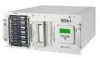
ProLiant ML370 Maintenance and Service Guide
Page 2
... and/or service marks of this publication is subject to change without prior written consent from Compaq Computer Corporation. © 2000 Compaq Computer Corporation. COMPAQ COMPUTER CORPORATION SHALL NOT BE LIABLE FOR TECHNICAL OR EDITORIAL ERRORS OR OMISSIONS CONTAINED HEREIN, NOR... QuickFind, PaqFax, ProSignia, registered United States Patent and Trademark Office. This publication contains information protected by copyright. Compaq ProLiant ML370 Maintenance and Service Guide Maintenance and Service Guide Fourth Edition (June 2000) Part Number 143091-004 Spare Part Number ...
ProLiant ML370 Maintenance and Service Guide
Page 4
iv Compaq ProLiant ML370 Maintenance and Service Guide Removal and Replacement Procedures continued I/O Fan...2-22 Power Switch with Cable and LED Indicators 2-23 Riser Board Expansion ...37 Internal Replacement Battery 2-38 Chapter 3 Diagnostics and Troubleshooting Diagnostic Tools Utility Overview 3-2 Default Configuration 3-4 Default Configuration Messages 3-4 Inspect Utility...3-4 Utilities Access...3-5 Running Compaq Utilities 3-5 Power-On Self-Test (POST 3-7 POST Error Messages 3-7 Diagnostics Software 3-26 Steps for Diagnostics 3-26 100-199, Primary Processor Test Error Codes 3-...
ProLiant ML370 Maintenance and Service Guide
Page 5
... Unit ...5-2 Power Supply ...5-3 Redundant Power Supply 5-4 Dual Inline Memory Modules (DIMM 5-5 1.44-MB Diskette Drive 5-5 IDE CD-ROM Drive 5-6 Compaq Wide Ultra2 Hot-Plug SCSI Hard Drives 5-7 Integrated Dual Channel SCSI Controller 5-8 Index System Identification ...Error Recovery Options 3-64 ROMPaq Disaster Recovery 3-65 Compaq Insight Manager 3-67 Features of Compaq Insight Management 3-67 Compaq Insight Management Software Architecture 3-68 Chapter 4 Connectors, Switches, and LED Indicators Compaq ProLiant ML370 System Board Components 4-2 Rear Panel Components 4-3 Switches...
ProLiant ML370 Maintenance and Service Guide
Page 7
... of the procedures, precautions, and hazards associated with equipment containing hazardous energy circuits. Symbols in Text These symbols may be used for reference when servicing Compaq ProLiant ML370 Servers. CAUTION: Text set off in this manner presents commentary, sidelights, or interesting points of information. About This Guide This maintenance and service guide is...
ProLiant ML370 Maintenance and Service Guide
Page 8
... system, you must provide at least 12 inches (30.5 cm) of repair specified in these procedures. IMPORTANT: Any indications of the computer. viii Compaq ProLiant ML370 Maintenance and Service Guide Compaq Technician Notes WARNING: Only authorized technicians trained by unplugging all times. CAUTION: The computer is an important safety feature. Plug the power cord...
ProLiant ML370 Maintenance and Service Guide
Page 10
1 Chapter Illustrated Parts Catalog This chapter provides the illustrated parts breakdown and a spare parts list for the names of referenced spare parts. See Table 1-1 and Table 1-2 for Compaq ProLiant™ ML370 Servers.
ProLiant ML370 Maintenance and Service Guide
Page 15
1-6 Compaq ProLiant ML370 Maintenance and Service Guide Table 1-2 System Components Spare Parts List continued Item Description Cables continued 24 Miscellaneous signal cable kit * a) Hard drive/CD-ROM drive ..., pair (rackmount model only) 32 Rack conversion kit * 33 Keyboard * 34 Baffle * Options 35 64-MB, 133-MHz, registered SDRAM dual inline memory module * 36 256-MB, 133-MHz, registered SDRAM dual inline memory module * 37 512-MB, 133-MHz, registered SDRAM dual inline memory module * 38 1-GB, 133-MHz, registered SDRAM dual...
ProLiant ML370 Maintenance and Service Guide
Page 17
... completing all necessary removal and replacement procedures, run the diagnostics program to verify that all components operate properly. To service Compaq ProLiant ML370 Servers, you might need the following: Torx T-15 screwdriver From the Compaq SmartStart and Support Software CD: System Configuration Utility Drive Array Advanced Diagnostics Diagnostics 2 Chapter Removal and Replacement Procedures This...
ProLiant ML370 Maintenance and Service Guide
Page 18
... product is contacted, the potential for injury exists. Avoid touching pins, leads, or circuitry. Symbols in their containers until they arrive at static-free stations. 2-2 Compaq ProLiant ML370 Maintenance and Service Guide Electrostatic Discharge Information A discharge of your CD-ROM drive. Cover work surface and properly grounded tools and equipment. WARNING: Any RJ...
ProLiant ML370 Maintenance and Service Guide
Page 19
.... WARNING: To reduce the risk of injury from the system, you must be powered down. Powering Down the Server System power in ProLiant ML370 Servers does not completely shut off the server to remove any reason. The standby position removes power from the system. WARNING: To reduce... portions of personal injury or damage to the equipment, ensure that came with the server. Hot-Pluggable Devices Hot-pluggable devices in the ProLiant ML370 Servers include SCSI hard drives and power supplies (with the front panel Power On/Standby switch. Removal and Replacement Procedures 2-3 Weight in kg...
ProLiant ML370 Maintenance and Service Guide
Page 20
...sure that the system power LED indicator on the front panel, near the Power On/Standby switch, is critical. Refer to the ProLiant ML370 Servers Setup and Installation Guide for any installation procedure. This places the server in standby mode, thereby disabling the main power supply...rack and place it on a sturdy table or workbench. Disconnect all power cords from the server to the ProLiant ML370 Servers Setup and Installation Guide for instructions. 2-4 Compaq ProLiant ML370 Maintenance and Service Guide WARNING: To reduce the risk of personal injury or damage to the equipment: If ...
ProLiant ML370 Maintenance and Service Guide
Page 21
... and voltage spikes and keeps the system in operation during a power failure. Proper cooling will not be operated with a regulating uninterruptible power supply (UPS). CAUTION: ProLiant ML370 Servers must always be achieved if the system unit cover is removed. Install the power supply before removing the power supply from the system by...
ProLiant ML370 Maintenance and Service Guide
Page 22
Swing the front bezel out away from the chassis. Removing the front bezel Reverse steps 1 through 3 to the ProLiant ML370 tower model only. To open the front bezel: 1. To remove the front bezel, continue with the following step. 3. Unlock the front bezel keylock. 2. 2-6 Compaq ProLiant ML370 Maintenance and Service Guide Front Bezel NOTE: This procedure applies to replace the front bezel. Figure 2-1. Lift up the front bezel, then pull it away from the server.
ProLiant ML370 Maintenance and Service Guide
Page 23
To remove the rack front plate: 1. Removal and Replacement Procedures 2-7 Rack Front Plate NOTE: This procedure applies to replace the rack front plate. Pull the rack front plate away from the rack front plate . 2. Removing the rack front plate Reverse steps 1 and 2 to the ProLiant ML370 rack-mountable model only. Remove the ten T-15 screws from the server . 2 1 Figure 2-2.
ProLiant ML370 Maintenance and Service Guide
Page 24
... on its holder. Perform the preparation procedures. Pivot each foot snaps securely into its right side (opposite from the chassis Reverse steps 1 through 4 to the ProLiant ML370 tower model only. then pull it off the base of the chassis . 3 2 1 Figure 2-3. See "Powering Down the Server" earlier in this chapter. 2. Remove ..., one at a time: 1. To remove the feet from each foot . 4. Removing the feet from the large access panel). 3. Make sure each foot down ; 2-8 Compaq ProLiant ML370 Maintenance and Service Guide Feet NOTE: This procedure applies to replace the feet.
ProLiant ML370 Maintenance and Service Guide
Page 26
... cool before touching them. To remove the small access panel: 1. Loosen the thumbscrew securing the small access panel to replace the small access panel. 2-10 Compaq ProLiant ML370 Maintenance and Service Guide Small Access Panel WARNING: To reduce the risk of the unit about 1.5 cm (0.5 inches), then off to the side . 2 1 Figure 2-5. See...
ProLiant ML370 Maintenance and Service Guide
Page 28
... IDE CD-ROM drive. Two bays can contain a second CD-ROM drive, tape drives, hard drives, or any SCSI device. 2-12 Compaq ProLiant ML370 Maintenance and Service Guide Drives and Related Components Compaq ProLiant ML370 Servers ship standard with a hot-plug drive cage containing six 1.0-inch hot-plug drive bays. Drives and related components Table 2-1 Drives...
ProLiant ML370 Maintenance and Service Guide
Page 30
2-14 Compaq ProLiant ML370 Maintenance and Service Guide SCSI Cable Diagram 1 2 1 2 Figure 2-10. SCSI cable diagram: the three-device, terminated SCSI cable connected from internal SCSI Port 1 to the vacant bays of the removable media area, and the point-to-point SCSI cable connected from internal SCSI Port 2 to the backplane of the hot-plug drive cage
ProLiant ML370 Maintenance and Service Guide
Page 32
... the CD-ROM drive. Open the front bezel (tower model only). Slide the CD-ROM drive out the front of the chassis . 2 1 1 Figure 2-12. 2-16 Compaq ProLiant ML370 Maintenance and Service Guide IDE CD-ROM Drive To remove the CD-ROM drive: 1. See "Powering Down the Server" earlier in this chapter. 4. Removing the...
ProLiant ML370 Maintenance and Service Guide
Page 34
See "Front Bezel" earlier in an unused hard drive slot. Open the front bezel (tower model only). Squeeze the top and bottom tabs of the hard drive cage . 1 2 1 Figure 2-14. Removing a hard drive blank Reverse steps 1 through 3 to install a hard drive blank could result in system errors. Pull the blank out of the blank . 3. Failure to replace a hard drive blank. 2-18 Compaq ProLiant ML370 Maintenance and Service Guide Hard Drive Blank IMPORTANT: A hard drive blank must be installed in this chapter. 2. To remove a hard drive blank: 1.