Safety and Regulatory Information Desktops, Thin Clients, and Personal Workstations
Page 5
Table of contents 1 Safety Notices Important Safety Information ...1 Installation Conditions ...2 Battery Replacement Notice ...2 Headset and Earphone Volume Level Notice 3 German Ergonomics Notice ...3 Laser Safety ...3 CDRH Regulations ...3 Compliance with International Regulations 4 Laser Product Label ...4 Laser Information ...4 Power Supply ...
Table of contents 1 Safety Notices Important Safety Information ...1 Installation Conditions ...2 Battery Replacement Notice ...2 Headset and Earphone Volume Level Notice 3 German Ergonomics Notice ...3 Laser Safety ...3 CDRH Regulations ...3 Compliance with International Regulations 4 Laser Product Label ...4 Laser Information ...4 Power Supply ...
Safety and Regulatory Information Desktops, Thin Clients, and Personal Workstations
Page 8
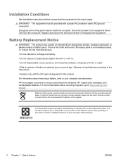
... The equipment must be disposed of the Waste Disposal Act, to your computer documentation. Battery Replacement Notice WARNING! For more information about removing a battery, refer to indicate the recovery marks on the batteries used electronic hardware, HP original print cartridges, and rechargeable batteries. In order to forward them to recycling or proper disposal, please use the...
... The equipment must be disposed of the Waste Disposal Act, to your computer documentation. Battery Replacement Notice WARNING! For more information about removing a battery, refer to indicate the recovery marks on the batteries used electronic hardware, HP original print cartridges, and rechargeable batteries. In order to forward them to recycling or proper disposal, please use the...

Hardware Reference Guide - dc7600 CMT
Page 4
... an Optical or other Removable Storage Device 2-24 Installing a SATA Hard Drive into a 3.5-inch Drive Bay 2-27 Removing a Drive from the Drive Bay 2-30 A Specifications B Battery Replacement C Security Lock Provisions Installing a Security Lock C-1 Cable Lock C-1 Padlock C-2 Universal Chassis Clamp Lock C-3 D Electrostatic Discharge Preventing Electrostatic Damage D-1 Grounding Methods D-1 E Computer Operating Guidelines, Routine Care...
... an Optical or other Removable Storage Device 2-24 Installing a SATA Hard Drive into a 3.5-inch Drive Bay 2-27 Removing a Drive from the Drive Bay 2-30 A Specifications B Battery Replacement C Security Lock Provisions Installing a Security Lock C-1 Cable Lock C-1 Padlock C-2 Universal Chassis Clamp Lock C-3 D Electrostatic Discharge Preventing Electrostatic Damage D-1 Grounding Methods D-1 E Computer Operating Guidelines, Routine Care...

Hardware Reference Guide - dc7600 CMT
Page 52
...wall socket. Hardware Reference Guide www.hp.com B-1 In order to forward them to recycling or proper disposal, please use a battery equivalent to the battery originally installed in fire or water. ■ Replace the battery only with the HP spare designated for information on the... Documentation and Diagnostics CD for this product. Ä CAUTION: Before replacing the battery, it is important to ...
...wall socket. Hardware Reference Guide www.hp.com B-1 In order to forward them to recycling or proper disposal, please use a battery equivalent to the battery originally installed in fire or water. ■ Replace the battery only with the HP spare designated for information on the... Documentation and Diagnostics CD for this product. Ä CAUTION: Before replacing the battery, it is important to ...

Hardware Reference Guide - dc7600 CMT
Page 53
.... 4. Disconnect the power cord from the power outlet and disconnect any external devices. Lift the battery out of the computer or optional equipment. Battery Replacement Ä CAUTION: Static electricity can damage the electronic components of its holder. B-2 www.hp.com Hardware Reference Guide Then remove the computer access panel. ✎ It may be necessary...
.... 4. Disconnect the power cord from the power outlet and disconnect any external devices. Lift the battery out of the computer or optional equipment. Battery Replacement Ä CAUTION: Static electricity can damage the electronic components of its holder. B-2 www.hp.com Hardware Reference Guide Then remove the computer access panel. ✎ It may be necessary...

Hardware Reference Guide - dc7600 CMT
Page 54
b. Push the other edge down until the clamp snaps over the other edge of the battery. To release the battery from its holder, squeeze the metal clamp that extends above one edge of the replacement battery under the holder's lip with the positive side up , lift it out 1. To insert the new battery, slide one edge of the battery 2. When the battery pops up . Removing and Replacing a Coin Cell Battery (Type 2) Hardware Reference Guide www.hp.com B-3 Battery Replacement Type 2 a.
b. Push the other edge down until the clamp snaps over the other edge of the battery. To release the battery from its holder, squeeze the metal clamp that extends above one edge of the replacement battery under the holder's lip with the positive side up , lift it out 1. To insert the new battery, slide one edge of the battery 2. When the battery pops up . Removing and Replacing a Coin Cell Battery (Type 2) Hardware Reference Guide www.hp.com B-3 Battery Replacement Type 2 a.

Hardware Reference Guide - dc7600 CMT
Page 55
Battery Replacement Type 3 a. Removing a Coin Cell Battery (Type 3) ✎ After the battery has been replaced, use Computer Setup to the computer. 7. b. Refer to complete this procedure. 5. B-4 www.hp.com Hardware Reference Guide Insert the new battery and position the clip back into place. Replace the computer access panel. 6. Plug in place, and remove the battery 2. ... and time, your passwords, and any special system setups, using Computer Setup. Pull back on the clip 1 that is holding the battery in the computer and turn on the Documentation and Diagnostics CD. 8.
Battery Replacement Type 3 a. Removing a Coin Cell Battery (Type 3) ✎ After the battery has been replaced, use Computer Setup to the computer. 7. b. Refer to complete this procedure. 5. B-4 www.hp.com Hardware Reference Guide Insert the new battery and position the clip back into place. Replace the computer access panel. 6. Plug in place, and remove the battery 2. ... and time, your passwords, and any special system setups, using Computer Setup. Pull back on the clip 1 that is holding the battery in the computer and turn on the Documentation and Diagnostics CD. 8.

Hardware Reference Guide - dc7600 CMT
Page 67
Index A access panel locking and unlocking 2-2, C-1 removing 2-4 application key 1-4 audio connectors 1-2, 1-3 B battery replacement B-1 bezel See front bezel C CD-ROM drive See optical drive changing computer configuration 1-7, 1-10 components front panel 1-2 keyboard 1-4 rear panel 1-3 computer access panel...discharge, preventing damage D-1 expansion card installing 2-15 PCI 2-15 PCI Express 2-15, 2-19 removing 2-15 slot locations 2-15 expansion slot cover removing 2-17 replacing 2-19 F front bezel blanks 2-8 removing 2-6 replacing 2-7 front panel components 1-2 Hardware Reference Guide www...
Index A access panel locking and unlocking 2-2, C-1 removing 2-4 application key 1-4 audio connectors 1-2, 1-3 B battery replacement B-1 bezel See front bezel C CD-ROM drive See optical drive changing computer configuration 1-7, 1-10 components front panel 1-2 keyboard 1-4 rear panel 1-3 computer access panel...discharge, preventing damage D-1 expansion card installing 2-15 PCI 2-15 PCI Express 2-15, 2-19 removing 2-15 slot locations 2-15 expansion slot cover removing 2-17 replacing 2-19 F front bezel blanks 2-8 removing 2-6 replacing 2-7 front panel components 1-2 Hardware Reference Guide www...

HP Compaq Business PC dc7600 Series Personal Computer Illustrated Parts Map, CMT Chassis (1st Edition)
Page 2
...Locate the header and jumper labeled E49. 4. Replace the access panel. 6. To re-enable the password features, repeat steps 1-3, then replace the jumper on the system board. 4. Repeat steps 5-6, then establish new passwords. Remove the access panel. 3. Replace the access panel. 5. Disabling or Clearing ...Port connector Third Serial ATA (SATA) Port connector Fourth Serial ATA (SATA) Port connector CPU fan Hood lock Hood sensor Battery Memory socket Memory socket Memory socket Memory socket Microprocessor socket Clearing CMOS The computer's configuration (CMOS) may occasionally be OFF)....
...Locate the header and jumper labeled E49. 4. Replace the access panel. 6. To re-enable the password features, repeat steps 1-3, then replace the jumper on the system board. 4. Repeat steps 5-6, then establish new passwords. Remove the access panel. 3. Replace the access panel. 5. Disabling or Clearing ...Port connector Third Serial ATA (SATA) Port connector Fourth Serial ATA (SATA) Port connector CPU fan Hood lock Hood sensor Battery Memory socket Memory socket Memory socket Memory socket Microprocessor socket Clearing CMOS The computer's configuration (CMOS) may occasionally be OFF)....

Troubleshooting Guide
Page 18
... RTC battery. See the Hardware Reference Guide on the Documentation and Diagnostics CD for at least four seconds until the computer turns off when the power button is in Computer Setup. 2-6 www.hp.com Troubleshooting Guide The Num Lock light should not be on the keypad. Press the power button...want to resume from the electrical outlet. Computer date and time display is not functional. 1. Cursor will shut down the power button for RTC battery replacement. The Num Lock key can also be used to a live AC outlet prolongs the life of the power switch is incorrect.
... RTC battery. See the Hardware Reference Guide on the Documentation and Diagnostics CD for at least four seconds until the computer turns off when the power button is in Computer Setup. 2-6 www.hp.com Troubleshooting Guide The Num Lock light should not be on the keypad. Press the power button...want to resume from the electrical outlet. Computer date and time display is not functional. 1. Cursor will shut down the power button for RTC battery replacement. The Num Lock key can also be used to a live AC outlet prolongs the life of the power switch is incorrect.

Troubleshooting Guide
Page 61
...set Advanced > Device Options > NIC PXE Option ROM Download to DISABLE to prevent PXE option ROM for RTC battery replacement. If the problem persists, replace the RTC battery. Reset the date and time under Control Panel. Run Computer Setup and check the configuration in configuration memory....Memory Space for RTC battery replacement. 163-Time & Date Not Set Invalid time or date in Advanced > Onboard Devices. Internal PXE option ROM is enabled 162-System Options Not Set Configuration incorrect. Troubleshooting Guide www.hp.com A-3 RTC (real-time clock) battery may need to be...
...set Advanced > Device Options > NIC PXE Option ROM Download to DISABLE to prevent PXE option ROM for RTC battery replacement. If the problem persists, replace the RTC battery. Reset the date and time under Control Panel. Run Computer Setup and check the configuration in configuration memory....Memory Space for RTC battery replacement. 163-Time & Date Not Set Invalid time or date in Advanced > Onboard Devices. Internal PXE option ROM is enabled 162-System Options Not Set Configuration incorrect. Troubleshooting Guide www.hp.com A-3 RTC (real-time clock) battery may need to be...

Troubleshooting Guide
Page 83
Index A access panel, removing 2-7 audible codes A-12 audio problems 2-23 B battery, replacing 2-6 beep codes A-12 blank screen 2-18 booting options Full Boot A-1 Quick Boot A-1 C CD-ROM or DVD problems 2-39 CMOS backing up B-1 button B-1, B-3 clearing and resetting B-3 ... blinking power A-12 blinking PS/2 keyboard A-12 M memory error codes A-4 solving problems 2-37 monitor blank screen 2-18 blurry video 2-20 checking connections 2-5 Troubleshooting Guide www.hp.com Index-1
Index A access panel, removing 2-7 audible codes A-12 audio problems 2-23 B battery, replacing 2-6 beep codes A-12 blank screen 2-18 booting options Full Boot A-1 Quick Boot A-1 C CD-ROM or DVD problems 2-39 CMOS backing up B-1 button B-1, B-3 clearing and resetting B-3 ... blinking power A-12 blinking PS/2 keyboard A-12 M memory error codes A-4 solving problems 2-37 monitor blank screen 2-18 blurry video 2-20 checking connections 2-5 Troubleshooting Guide www.hp.com Index-1

Getting Started
Page 20
...on. Cursor will need to be disabled (or enabled) in case of the RTC battery. If the problem persists, replace the RTC battery. The Num Lock key can also be on installing a new battery, or contact an authorized dealer or reseller for instructions on if you want to ...life of forgotten password, power loss, or computer malfunction. 16 www.hp.com Getting Started Cannot remove computer cover or access panel. See the Hardware Reference Guide on the Documentation and Diagnostics CD for RTC battery replacement. The Num Lock key may need the FailSafe Key in Computer ...
...on. Cursor will need to be disabled (or enabled) in case of the RTC battery. If the problem persists, replace the RTC battery. The Num Lock key can also be on installing a new battery, or contact an authorized dealer or reseller for instructions on if you want to ...life of forgotten password, power loss, or computer malfunction. 16 www.hp.com Getting Started Cannot remove computer cover or access panel. See the Hardware Reference Guide on the Documentation and Diagnostics CD for RTC battery replacement. The Num Lock key may need the FailSafe Key in Computer ...

Getting Started - Enhanced for Accessibility
Page 20
...need to be replaced. ✎ Connecting the computer to a live AC outlet prolongs the life of forgotten password, power loss, or computer malfunction. 16 www.hp.com Getting Started The Num Lock key can also be disabled (or enabled) in case of the RTC battery. Cannot remove...9998; This feature is incorrect. The Smart Cover FailSafe Key, a device for RTC battery replacement. See the Hardware Reference Guide on the Documentation and Diagnostics CD for instructions on installing a new battery, or contact an authorized dealer or reseller for manually disabling the Smart Cover Lock, is...
...need to be replaced. ✎ Connecting the computer to a live AC outlet prolongs the life of forgotten password, power loss, or computer malfunction. 16 www.hp.com Getting Started The Num Lock key can also be disabled (or enabled) in case of the RTC battery. Cannot remove...9998; This feature is incorrect. The Smart Cover FailSafe Key, a device for RTC battery replacement. See the Hardware Reference Guide on the Documentation and Diagnostics CD for instructions on installing a new battery, or contact an authorized dealer or reseller for manually disabling the Smart Cover Lock, is...

Hardware Guide
Page 4
Contents Upgrading the SATA Hard Drive 2-33 Installing an Optional Drive into the 3.5-inch Drive Bay 2-39 A Specifications B Battery Replacement C Security Lock Provisions Installing a Security Lock C-1 Cable Lock C-1 Padlock C-2 Universal Chassis Clamp Lock C-3 D Electrostatic Discharge Preventing Electrostatic Damage D-1 Grounding Methods D-1 E Computer Operating Guidelines, Routine Care ...
Contents Upgrading the SATA Hard Drive 2-33 Installing an Optional Drive into the 3.5-inch Drive Bay 2-39 A Specifications B Battery Replacement C Security Lock Provisions Installing a Security Lock C-1 Cable Lock C-1 Padlock C-2 Universal Chassis Clamp Lock C-3 D Electrostatic Discharge Preventing Electrostatic Damage D-1 Grounding Methods D-1 E Computer Operating Guidelines, Routine Care ...

Hardware Guide
Page 56
.... Hardware Reference Guide www.hp.com B-1 When the battery is important to AC power. Å WARNING: The computer contains an internal lithium manganese dioxide battery. N Batteries, battery packs, and accumulators should not be disposed of fire and burns if the battery is NOT connected to back up the CMOS settings. B Battery Replacement The battery that comes with the general...
.... Hardware Reference Guide www.hp.com B-1 When the battery is important to AC power. Å WARNING: The computer contains an internal lithium manganese dioxide battery. N Batteries, battery packs, and accumulators should not be disposed of fire and burns if the battery is NOT connected to back up the CMOS settings. B Battery Replacement The battery that comes with the general...

Hardware Guide
Page 57
.... Disconnect the power cord from the power outlet and disconnect any external devices. B-2 www.hp.com Hardware Reference Guide Then remove the computer cover. ✎ It may be necessary to remove an expansion card to gain access to replace the battery. Battery Replacement Ä CAUTION: Static electricity can damage the electronic components of its holder.
.... Disconnect the power cord from the power outlet and disconnect any external devices. B-2 www.hp.com Hardware Reference Guide Then remove the computer cover. ✎ It may be necessary to remove an expansion card to gain access to replace the battery. Battery Replacement Ä CAUTION: Static electricity can damage the electronic components of its holder.

Hardware Guide
Page 58
When the battery pops up . To insert the new battery, slide one edge of the battery. Push the other edge down until the clamp snaps over the other edge of the replacement battery under the holder's lip with the positive side up , lift it out 1. b. Removing and Replacing a Coin Cell Battery (Type 2) Hardware Reference Guide www.hp.com B-3 Battery Replacement Type 2 a. To release the battery from its holder, squeeze the metal clamp that extends above one edge of the battery 2.
When the battery pops up . To insert the new battery, slide one edge of the battery. Push the other edge down until the clamp snaps over the other edge of the replacement battery under the holder's lip with the positive side up , lift it out 1. b. Removing and Replacing a Coin Cell Battery (Type 2) Hardware Reference Guide www.hp.com B-3 Battery Replacement Type 2 a. To release the battery from its holder, squeeze the metal clamp that extends above one edge of the battery 2.

Hardware Guide
Page 59
... Computer Setup to the computer. 7. Refer to complete this procedure. 5. Replace the computer cover. 6. b. Battery Replacement Type 3 a. Plug in place, and remove the battery 2. B-4 www.hp.com Hardware Reference Guide Pull back on the clip 1 that is holding the battery in the computer and turn on the Documentation and Diagnostics CD. 8. Reset the date and time...
... Computer Setup to the computer. 7. Refer to complete this procedure. 5. Replace the computer cover. 6. b. Battery Replacement Type 3 a. Plug in place, and remove the battery 2. B-4 www.hp.com Hardware Reference Guide Pull back on the clip 1 that is holding the battery in the computer and turn on the Documentation and Diagnostics CD. 8. Reset the date and time...

Hardware Guide
Page 71
...application key 1-4 audio connectors 1-2, 1-3, 2-15 B battery replacement B-1 bezel installing 2-43 part numbers 2-20, 2-39, 2-43 removing 2-42 C cable lock, installing C-1 chassis clamp lock, installing C-3 components front panel 1-2 rear panel 1-3 computer cover removing 2-5 replacing 2-6 Smart Cover Lock 2-3 computer operating guidelines E-1 ... using 2-3 front panel components 1-2 G guide screws 2-19, 2-28, 2-40 guidelines battery replacement B-1 computer operating E-1 drive installation 2-19 optical drive E-2 servicing the computer 2-1 shipping preparation E-3 Hardware Reference Guide www...
...application key 1-4 audio connectors 1-2, 1-3, 2-15 B battery replacement B-1 bezel installing 2-43 part numbers 2-20, 2-39, 2-43 removing 2-42 C cable lock, installing C-1 chassis clamp lock, installing C-3 components front panel 1-2 rear panel 1-3 computer cover removing 2-5 replacing 2-6 Smart Cover Lock 2-3 computer operating guidelines E-1 ... using 2-3 front panel components 1-2 G guide screws 2-19, 2-28, 2-40 guidelines battery replacement B-1 computer operating E-1 drive installation 2-19 optical drive E-2 servicing the computer 2-1 shipping preparation E-3 Hardware Reference Guide www...

