
Hardware Installation Guide
Page 3
... Obtaining Documentation and Submitting a Service Request i-xiv Product Overview 1-1 Interconnect Features 1-1 Cisco UCS 6120XP Chassis 1-2 Cisco UCS 6140XP Chassis 1-4 Expansion Modules 1-6 N10-E0440 1-7 N10-E0600 1-8 N10-E0080 1-8 N10-E0060 1-9 Ports 1-10 Cisco UCS 6120XP 1-10 Cisco UCS 6140XP 1-12 Power Supply 1-14 Fan Module 1-16 LED Descriptions 1-17 Port Level LEDs 1-18 Supported Transceivers 1-18 SFP...
... Obtaining Documentation and Submitting a Service Request i-xiv Product Overview 1-1 Interconnect Features 1-1 Cisco UCS 6120XP Chassis 1-2 Cisco UCS 6140XP Chassis 1-4 Expansion Modules 1-6 N10-E0440 1-7 N10-E0600 1-8 N10-E0080 1-8 N10-E0060 1-9 Ports 1-10 Cisco UCS 6120XP 1-10 Cisco UCS 6140XP 1-12 Power Supply 1-14 Fan Module 1-16 LED Descriptions 1-17 Port Level LEDs 1-18 Supported Transceivers 1-18 SFP...

Hardware Installation Guide
Page 4
... Power Supplies 2-24 Removing a Power Supply 2-24 Installing a Power Supply 2-25 Fan Modules 2-26 Replacing a Fan Module 2-26 Removing the Cisco UCS 6120XP 2-28 Removing the Cisco UCS 6140XP 2-28 Repacking the Cisco UCS Fabric Interconnect for Return Shipment 2-29 3 C H A P T E R Connecting the Cisco UCS 6100 Series Fabric Interconnect 3-1 Preparing for Network Connections 3-1 Connecting to the Console...
... Power Supplies 2-24 Removing a Power Supply 2-24 Installing a Power Supply 2-25 Fan Modules 2-26 Replacing a Fan Module 2-26 Removing the Cisco UCS 6120XP 2-28 Removing the Cisco UCS 6140XP 2-28 Repacking the Cisco UCS Fabric Interconnect for Return Shipment 2-29 3 C H A P T E R Connecting the Cisco UCS 6100 Series Fabric Interconnect 3-1 Preparing for Network Connections 3-1 Connecting to the Console...

Hardware Installation Guide
Page 5
... and Power Requirements Specification for SFP Transceivers A-4 B A P P E N D I X Accessory Kit for the Cisco UCS Fabric Interconnect B-1 Console Cable B-2 Console Port B-2 Supported Power Cords and Plugs B-3 AC Power Cord Illustrations B-4 Jumper Power Cord B-8 C A P P E N D I X Site Preparation Checklist C-1 Contact and Site Information C-3 Chassis and Module Information C-4 D A P P E N D I X Overview D-1 SNMP Traps D-1 System Hardware Best Practices D-2 Installation Best Practices...
... and Power Requirements Specification for SFP Transceivers A-4 B A P P E N D I X Accessory Kit for the Cisco UCS Fabric Interconnect B-1 Console Cable B-2 Console Port B-2 Supported Power Cords and Plugs B-3 AC Power Cord Illustrations B-4 Jumper Power Cord B-8 C A P P E N D I X Site Preparation Checklist C-1 Contact and Site Information C-3 Chassis and Module Information C-4 D A P P E N D I X Overview D-1 SNMP Traps D-1 System Hardware Best Practices D-2 Installation Best Practices...

Hardware Installation Guide
Page 7
... technician. It also provides information on how to connect the Cisco UCS 6100 Series Fabric Interconnect, including the modules. Lists specifications for the Cisco UCS 6100 Series Fabric Interconnect. Lists cable and port specifications for the Cisco UCS 6100 Series Fabric Interconnect and components including modules, power supplies, and transceivers. Send document comments to install...
... technician. It also provides information on how to connect the Cisco UCS 6100 Series Fabric Interconnect, including the modules. Lists specifications for the Cisco UCS 6100 Series Fabric Interconnect. Lists cable and port specifications for the Cisco UCS 6100 Series Fabric Interconnect and components including modules, power supplies, and transceivers. Send document comments to install...
Hardware Installation Guide
Page 15
... Ethernet and Fibre Channel to all servers in a cost-effective, high-performance, low-latency environment. Each fan module houses six fans. OL-20036-02 Cisco UCS 6100 Series Fabric Interconnect Hardware Installation Guide 1-1 The combination of fabric interconnects connect UCS servers to 10 Gigabit... and their components, and includes the following characteristics: • Depending on the model and expansion modules used, 20 to56 ports are four expansion modules available for the Cisco UCS 6100 series: N10-E0080 (eight Fiber Channel ports), N10-E0060 (six Fiber Channel ports),...
... Ethernet and Fibre Channel to all servers in a cost-effective, high-performance, low-latency environment. Each fan module houses six fans. OL-20036-02 Cisco UCS 6100 Series Fabric Interconnect Hardware Installation Guide 1-1 The combination of fabric interconnects connect UCS servers to 10 Gigabit... and their components, and includes the following characteristics: • Depending on the model and expansion modules used, 20 to56 ports are four expansion modules available for the Cisco UCS 6100 series: N10-E0080 (eight Fiber Channel ports), N10-E0060 (six Fiber Channel ports),...

Hardware Installation Guide
Page 16
... port exposes four Ethernet ports that are in a standard 19-inch rack (the Cisco R Series Rack is 1 RU, 1.72 inches tall, 17.3 inches wide and 30.0 inches deep. The chassis has two power supplies and two fan modules on the front of the chassis, and it has network ports on the rear... of the Cisco UCS 6120XP. Cisco UCS 6120XP Chassis Chapter 1 Product Overview Send document comments to back. Figure 1-1 shows a close-up view...
... port exposes four Ethernet ports that are in a standard 19-inch rack (the Cisco R Series Rack is 1 RU, 1.72 inches tall, 17.3 inches wide and 30.0 inches deep. The chassis has two power supplies and two fan modules on the front of the chassis, and it has network ports on the rear... of the Cisco UCS 6120XP. Cisco UCS 6120XP Chassis Chapter 1 Product Overview Send document comments to back. Figure 1-1 shows a close-up view...

Hardware Installation Guide
Page 17
... ports, 1 slot for an optional expansion module, an Ethernet connector with 2 cross-connect ports and 2 management ports, a console port, and 2 AC power connectors. Figure 1-4 shows the rear of the chassis. Up to ucs-docfeedback@cisco.com Figure 1-2 Cisco UCS 6120XP Front View 189949 1 2 ...1 Two power supplies 2 Two fan modules Figure 1-3 shows a close-up 1 2 3 189950 1 Two power supplies 2 Two fan modules 3 System status LED The rear of the 20 ports...
... ports, 1 slot for an optional expansion module, an Ethernet connector with 2 cross-connect ports and 2 management ports, a console port, and 2 AC power connectors. Figure 1-4 shows the rear of the chassis. Up to ucs-docfeedback@cisco.com Figure 1-2 Cisco UCS 6120XP Front View 189949 1 2 ...1 Two power supplies 2 Two fan modules Figure 1-3 shows a close-up 1 2 3 189950 1 Two power supplies 2 Two fan modules 3 System status LED The rear of the 20 ports...

Hardware Installation Guide
Page 18
... 6140XP. It mounts in a standard 19-inch rack (the Cisco R Series Rack is front to back. Cisco UCS 6140XP Chassis Chapter 1 Product Overview Send document comments to ucs-docfeedback@cisco.com Figure 1-4 Cisco UCS 6120XP Rear View 1 2 3 4 1 System status LED 3 Console port 5 Expansion modules 5 6 2 Ethernet connector with two cross-connect ports on the left (top...
... 6140XP. It mounts in a standard 19-inch rack (the Cisco R Series Rack is front to back. Cisco UCS 6140XP Chassis Chapter 1 Product Overview Send document comments to ucs-docfeedback@cisco.com Figure 1-4 Cisco UCS 6120XP Rear View 1 2 3 4 1 System status LED 3 Console port 5 Expansion modules 5 6 2 Ethernet connector with two cross-connect ports on the left (top...

Hardware Installation Guide
Page 19
... view of the front of the chassis. Up to ucs-docfeedback@cisco.com Figure 1-5 Cisco UCS 6140XP Front View 186260 1 2 1 Two power supplies 2 Five fan modules Figure 1-3 shows a close-up 1 2 3 186261 1 Two power supplies 2 Five fan modules 3 System status LED The rear of the Cisco UCS 6140XP chassis has 40 fixed 10-Gigabit, FCoE-capable...
... view of the front of the chassis. Up to ucs-docfeedback@cisco.com Figure 1-5 Cisco UCS 6140XP Front View 186260 1 2 1 Two power supplies 2 Five fan modules Figure 1-3 shows a close-up 1 2 3 186261 1 Two power supplies 2 Five fan modules 3 System status LED The rear of the Cisco UCS 6140XP chassis has 40 fixed 10-Gigabit, FCoE-capable...

Hardware Installation Guide
Page 20
... module. Cisco UCS 6100 Series Fabric Interconnect Hardware Installation Guide 1-6 OL-20036-02 If the expansion modules are not in place, a cover plate should be accommodated in the chassis. The Cisco UCS 6120XP has one slot for an optional uplink expansion module.There...• N10-E0440 provides 4 10G SFP+, and 4 Fibre Channel 1/2/4G SFP-based uplink connections. Expansion Modules Chapter 1 Product Overview Send document comments to ucs-docfeedback@cisco.com Figure 1-7 Cisco UCS 6140XP Rear View 186265 1 2 3 4 5 6 1 System status LED 2 Ethernet connector with two...
... module. Cisco UCS 6100 Series Fabric Interconnect Hardware Installation Guide 1-6 OL-20036-02 If the expansion modules are not in place, a cover plate should be accommodated in the chassis. The Cisco UCS 6120XP has one slot for an optional uplink expansion module.There...• N10-E0440 provides 4 10G SFP+, and 4 Fibre Channel 1/2/4G SFP-based uplink connections. Expansion Modules Chapter 1 Product Overview Send document comments to ucs-docfeedback@cisco.com Figure 1-7 Cisco UCS 6140XP Rear View 186265 1 2 3 4 5 6 1 System status LED 2 Ethernet connector with two...

Hardware Installation Guide
Page 21
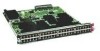
Figure 1-9 Front of the Fibre Channel plus Ethernet expansion module, and shows how ports are numbered on the Fibre Channel plus Ethernet expansion module. Chapter 1 Product Overview Expansion Modules Send document comments to ucs-docfeedback@cisco.com N10-E0440 The N10-E0440 supports four SFP+ transceiver modules and four 1-, 2-, 4-Gbps Fibre Channel transceivers. The Fibre Channel...
Figure 1-9 Front of the Fibre Channel plus Ethernet expansion module, and shows how ports are numbered on the Fibre Channel plus Ethernet expansion module. Chapter 1 Product Overview Expansion Modules Send document comments to ucs-docfeedback@cisco.com N10-E0440 The N10-E0440 supports four SFP+ transceiver modules and four 1-, 2-, 4-Gbps Fibre Channel transceivers. The Fibre Channel...

Hardware Installation Guide
Page 22
... Fabric Interconnect Hardware Installation Guide 1-8 OL-20036-02 Figure 1-10 shows the N10-E0600 expansion module. Figure 1-11 shows the N10-E0080 expansion module. Expansion Modules Chapter 1 Product Overview Send document comments to ucs-docfeedback@cisco.com N10-E0600 The N10-E0600 expansion module supports 6 10G SFP+ based uplink connections. Figure 1-10 N10-E0600 Expansion...
... Fabric Interconnect Hardware Installation Guide 1-8 OL-20036-02 Figure 1-10 shows the N10-E0600 expansion module. Figure 1-11 shows the N10-E0080 expansion module. Expansion Modules Chapter 1 Product Overview Send document comments to ucs-docfeedback@cisco.com N10-E0600 The N10-E0600 expansion module supports 6 10G SFP+ based uplink connections. Figure 1-10 N10-E0600 Expansion...

Hardware Installation Guide
Page 23
... Front of the N10-E0080 Expansion Module 1 1 23 4 5 6 7 8 189954 2 1 Eight 1-, 2-, 4-Gbps Fibre Channel ports 2 Module LED N10-E0060 The N10-E0060 expansion module supports 6 1/2/4/ 8 G Fibre Channel, SFP-based uplink connections. Figure 1-11 shows the N10-E0060 expansion module. Figure 1-13 N10-E0060 Expansion Module 196118 OL-20036-02 Cisco UCS 6100 Series Fabric Interconnect Hardware Installation...
... Front of the N10-E0080 Expansion Module 1 1 23 4 5 6 7 8 189954 2 1 Eight 1-, 2-, 4-Gbps Fibre Channel ports 2 Module LED N10-E0060 The N10-E0060 expansion module supports 6 1/2/4/ 8 G Fibre Channel, SFP-based uplink connections. Figure 1-11 shows the N10-E0060 expansion module. Figure 1-13 N10-E0060 Expansion Module 196118 OL-20036-02 Cisco UCS 6100 Series Fabric Interconnect Hardware Installation...

Hardware Installation Guide
Page 24
...installed. The ports are numbered based on which expansion module is numbered, and groups of ports are numbered top to bottom and left to ucs-docfeedback@cisco.com Figure 1-14 Front of the N10-E0060 Expansion Module 1 1/2/4/8G FIBRE CHANNEL 196117 12 34 56 2 ... Of these, ports 1 through 16 are 10-Gigabit Ethernet and 1-Gigabit Ethernet-capable ports. Expansion Modules Chapter 1 Product Overview Send document comments to right. Ports 17 1-10 Cisco UCS 6100 Series Fabric Interconnect Hardware Installation Guide OL-20036-02 Ports 1 through 8 are unencrypted Ethernet ...
...installed. The ports are numbered based on which expansion module is numbered, and groups of ports are numbered top to bottom and left to ucs-docfeedback@cisco.com Figure 1-14 Front of the N10-E0060 Expansion Module 1 1/2/4/8G FIBRE CHANNEL 196117 12 34 56 2 ... Of these, ports 1 through 16 are 10-Gigabit Ethernet and 1-Gigabit Ethernet-capable ports. Expansion Modules Chapter 1 Product Overview Send document comments to right. Ports 17 1-10 Cisco UCS 6100 Series Fabric Interconnect Hardware Installation Guide OL-20036-02 Ports 1 through 8 are unencrypted Ethernet ...

Hardware Installation Guide
Page 25
...through 16: Unencrypted Ethernet ports E Group 2 ports 5 through 8: Fibre Channel ports C Group 1 ports 17 through 4 are numbered and grouped by function on a Cisco UCS 6120XP with the N10-E0600 Expansion Module A B C D E 1 3 5 7 9 11 13 15 17 19 1 3 5 1 2 2 4 6 8 10 12 14 16 18 20 2...8 are encryption-capable Ethernet ports. Group 2 includes the ports in the expansion module or modules. Chapter 1 Product Overview Expansion Modules Send document comments to ucs-docfeedback@cisco.com through 20 are Fibre Channel ports. Group 2 ports 5 through 20: ...
...through 16: Unencrypted Ethernet ports E Group 2 ports 5 through 8: Fibre Channel ports C Group 1 ports 17 through 4 are numbered and grouped by function on a Cisco UCS 6120XP with the N10-E0600 Expansion Module A B C D E 1 3 5 7 9 11 13 15 17 19 1 3 5 1 2 2 4 6 8 10 12 14 16 18 20 2...8 are encryption-capable Ethernet ports. Group 2 includes the ports in the expansion module or modules. Chapter 1 Product Overview Expansion Modules Send document comments to ucs-docfeedback@cisco.com through 20 are Fibre Channel ports. Group 2 ports 5 through 20: ...

Hardware Installation Guide
Page 26
... 1/port_number. Group 2 ports 1 through 4 are encrypted Ethernet ports. Group 3 ports 1 through 4 are encrypted Ethernet ports. Figure 1-18 Port Numbering of the Cisco UCS 6120XP Configured with the N10-E0080 Expansion Module A B C D 1 3 5 7 1 2 4 6 8 9 11 13 15 10 12 14 16 17 19 2 18 20 1 3 5 7 2 4 ...Channel ports. Group 2 includes the ports in the bottom-most expansion module. Ports 33 through 6: Fibre Channel ports Cisco UCS 6140XP There are 40 to ucs-docfeedback@cisco.com Figure 1-17 shows how ports are numbered and grouped by function ...
... 1/port_number. Group 2 ports 1 through 4 are encrypted Ethernet ports. Group 3 ports 1 through 4 are encrypted Ethernet ports. Figure 1-18 Port Numbering of the Cisco UCS 6120XP Configured with the N10-E0080 Expansion Module A B C D 1 3 5 7 1 2 4 6 8 9 11 13 15 10 12 14 16 17 19 2 18 20 1 3 5 7 2 4 ...Channel ports. Group 2 includes the ports in the bottom-most expansion module. Ports 33 through 6: Fibre Channel ports Cisco UCS 6140XP There are 40 to ucs-docfeedback@cisco.com Figure 1-17 shows how ports are numbered and grouped by function ...

Hardware Installation Guide
Page 27
... are numbered and grouped by function for both the fixed ports and the Fibre Channel plus Ethernet expansion module ports. Figure 1-19 Port Numbering of the Cisco UCS 6140XP Configured with the N10-E0080 Expansion Module A B C D E 186386 A Group 1/ports 1 through 16: 10-Gigabit Ethernet capable unencrypted ports B Group 1/ports 1 through 32: Unencrypted Ethernet...
... are numbered and grouped by function for both the fixed ports and the Fibre Channel plus Ethernet expansion module ports. Figure 1-19 Port Numbering of the Cisco UCS 6140XP Configured with the N10-E0080 Expansion Module A B C D E 186386 A Group 1/ports 1 through 16: 10-Gigabit Ethernet capable unencrypted ports B Group 1/ports 1 through 32: Unencrypted Ethernet...

Hardware Installation Guide
Page 28
... can be used for two power supplies. The chassis has slots for redundancy, but the fabric interconnect is fully functional with the N10-E0600 Expansion Module A B C D E 186387 A Group 1/ports 1 through 16: 10-Gigabit or 1 GigabitEthernet capable Encrypted ports B Group 1/ports 1 through 32: 10-Gigabit Unencrypted ... the 550 W power supply, which has two LEDs: one for power status and one power supply. Figure 1-20 Port Numbering of the Cisco UCS 6140XP Configured with one for failure condition. Figure 1-22 shows the 750 W power supply, which has two LEDs: one for power...
... can be used for two power supplies. The chassis has slots for redundancy, but the fabric interconnect is fully functional with the N10-E0600 Expansion Module A B C D E 186387 A Group 1/ports 1 through 16: 10-Gigabit or 1 GigabitEthernet capable Encrypted ports B Group 1/ports 1 through 32: 10-Gigabit Unencrypted ... the 550 W power supply, which has two LEDs: one for power status and one power supply. Figure 1-20 Port Numbering of the Cisco UCS 6140XP Configured with one for failure condition. Figure 1-22 shows the 750 W power supply, which has two LEDs: one for power...

Hardware Installation Guide
Page 30
... LED Status AC present, 3.3 voltage standby (VSB) on and OK. Figure 1-24 Cisco UCS 6120XP Fan Module (N10-FAN1=) 189956 1 1 Fan module LED 1-16 Cisco UCS 6100 Series Fabric Interconnect Hardware Installation Guide OL-20036-02 The combination of 6 fans per module and 2 modules provides the chassis with 12 fans. Figure 1-23 shows a blank power supply...
... LED Status AC present, 3.3 voltage standby (VSB) on and OK. Figure 1-24 Cisco UCS 6120XP Fan Module (N10-FAN1=) 189956 1 1 Fan module LED 1-16 Cisco UCS 6100 Series Fabric Interconnect Hardware Installation Guide OL-20036-02 The combination of 6 fans per module and 2 modules provides the chassis with 12 fans. Figure 1-23 shows a blank power supply...

Hardware Installation Guide
Page 31
... Series Fabric Interconnect Hardware Installation Guide 1-17 Figure 1-25 Cisco UCS 6140XP Fabric Interconnect Fan Module (N10-FAN2=) 1 186263 1 Fan module LED The bi-color fan module LED indicates fan tray health. Figure 1-25 shows the fan module. Table 1-4 LEDs for the Cisco UCS 6120XP and Cisco UCS 6140XP LED Location Color Description System Status Front of...
... Series Fabric Interconnect Hardware Installation Guide 1-17 Figure 1-25 Cisco UCS 6140XP Fabric Interconnect Fan Module (N10-FAN2=) 1 186263 1 Fan module LED The bi-color fan module LED indicates fan tray health. Figure 1-25 shows the fan module. Table 1-4 LEDs for the Cisco UCS 6120XP and Cisco UCS 6140XP LED Location Color Description System Status Front of...