
Hardware Installation Guide
Page 8
... that you work on any equipment, be aware of data. A warning symbol precedes each warning to ucs-docfeedback@cisco.com Chapter Title Appendix C Site Planning and Maintenance Records Appendix D Troubleshooting Hardware Components Description Provides site planning and maintenance...conventions for preventing accidents. U verkeert in the translated safety warnings that accompanied this publication in a situation that , if performed incorrectly, can cause physical injuries. Safety warnings appear throughout this device. Before you should be careful. You are in...
... that you work on any equipment, be aware of data. A warning symbol precedes each warning to ucs-docfeedback@cisco.com Chapter Title Appendix C Site Planning and Maintenance Records Appendix D Troubleshooting Hardware Components Description Provides site planning and maintenance...conventions for preventing accidents. U verkeert in the translated safety warnings that accompanied this publication in a situation that , if performed incorrectly, can cause physical injuries. Safety warnings appear throughout this device. Before you should be careful. You are in...
Hardware Installation Guide
Page 15
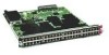
... Ethernet and Fibre Channel to all servers in a cost-effective, high-performance, low-latency environment. The Cisco UCS 6100 series has the following sections: • Interconnect Features, page 1-1 • Cisco UCS 6120XP Chassis, page 1-2 • Cisco UCS 6140XP Chassis, page 1-4 • Expansion Modules, page 1-6 •... characteristics: • Depending on the model and expansion modules used, 20 to56 ports are four expansion modules available for the Cisco UCS 6100 series: N10-E0080 (eight Fiber Channel ports), N10-E0060 (six Fiber Channel ports), N10-E0600 (six 10-...
... Ethernet and Fibre Channel to all servers in a cost-effective, high-performance, low-latency environment. The Cisco UCS 6100 series has the following sections: • Interconnect Features, page 1-1 • Cisco UCS 6120XP Chassis, page 1-2 • Cisco UCS 6140XP Chassis, page 1-4 • Expansion Modules, page 1-6 •... characteristics: • Depending on the model and expansion modules used, 20 to56 ports are four expansion modules available for the Cisco UCS 6100 series: N10-E0080 (eight Fiber Channel ports), N10-E0060 (six Fiber Channel ports), N10-E0600 (six 10-...

Hardware Installation Guide
Page 54
...modules are installed. Note Depending on the outlet receptacle on page 3-1. Starting the System Chapter 2 Installing the Cisco UCS 6100 Series Fabric Interconnect Send document comments to ucs-docfeedback@cisco.com Step 5 Step 6 Step 7 Place the grounding lug against the grounding pad so that there is... is solid metal-to work with washers through the holes in your site to the LAN until the initial system configuration has been performed. Warning When installing or replacing the unit, the ground connection must be made first and disconnected last. For a first-time installation...
...modules are installed. Note Depending on the outlet receptacle on page 3-1. Starting the System Chapter 2 Installing the Cisco UCS 6100 Series Fabric Interconnect Send document comments to ucs-docfeedback@cisco.com Step 5 Step 6 Step 7 Place the grounding lug against the grounding pad so that there is... is solid metal-to work with washers through the holes in your site to the LAN until the initial system configuration has been performed. Warning When installing or replacing the unit, the ground connection must be made first and disconnected last. For a first-time installation...

Hardware Installation Guide
Page 61
... system (earth) ground connection has been made. See the "Jumper Power Cord" section on the fan module by checking that the replacement is performed promptly. Caution In a system with dual power supplies, connect each power supply to your outlet receptacle. Replacing a Fan Module Warning When removing ...unit, you remove the fan tray. Let the fan blades completely stop before you may need the optional jumper power cord to connect the Cisco UCS 6100 Series Fabric Interconnect to a separate power source. Step 5 Connect the other end of the power supply bay. Loosen the captive...
... system (earth) ground connection has been made. See the "Jumper Power Cord" section on the fan module by checking that the replacement is performed promptly. Caution In a system with dual power supplies, connect each power supply to your outlet receptacle. Replacing a Fan Module Warning When removing ...unit, you remove the fan tray. Let the fan blades completely stop before you may need the optional jumper power cord to connect the Cisco UCS 6100 Series Fabric Interconnect to a separate power source. Step 5 Connect the other end of the power supply bay. Loosen the captive...
Hardware Installation Guide
Page 63
... 6100 Series Fabric Interconnect Hardware Installation Guide 2-29 If you purchased this URL: http://www.cisco.com/en/US/support/tsd_cisco_worldwide_contacts.html. Perform a backup of your UCS Manager configuration as mentioned in the "System Management" section, "Backing Up and Restoring ...both the active and standby fabric interconnect from a UCS system, or the sole fabric interconnect from a standalone system, you purchased this , perform the following tasks: 1. Decommision every attached chassis as decribed in the "System Management" section, "Managing Blade Servers" chapter of the ...
... 6100 Series Fabric Interconnect Hardware Installation Guide 2-29 If you purchased this URL: http://www.cisco.com/en/US/support/tsd_cisco_worldwide_contacts.html. Perform a backup of your UCS Manager configuration as mentioned in the "System Management" section, "Backing Up and Restoring ...both the active and standby fabric interconnect from a UCS system, or the sole fabric interconnect from a standalone system, you purchased this , perform the following tasks: 1. Decommision every attached chassis as decribed in the "System Management" section, "Managing Blade Servers" chapter of the ...

Hardware Installation Guide
Page 66
Figure 3-1 shows how to connect to the console port on a Cisco UCS 6140XP 186705 You can use the console port to perform the following: • Configure the Cisco UCS 6100 Series Fabric Interconnect from the CLI. • Monitor network statistics and errors. • Configure SNMP agent parameters. • Download software updates. Figure 3-1 Connecting ...
Figure 3-1 shows how to connect to the console port on a Cisco UCS 6140XP 186705 You can use the console port to perform the following: • Configure the Cisco UCS 6100 Series Fabric Interconnect from the CLI. • Monitor network statistics and errors. • Configure SNMP agent parameters. • Download software updates. Figure 3-1 Connecting ...

Hardware Installation Guide
Page 78
... Interconnect Hardware Installation Guide A-4 OL-20036-02 Table A-7 Environmental Conditions and Power Requirements Specifications for Cisco Fibre Channel SFP transceivers. Functional performance is not intended, device reliability is not implied, and damage to the device may occur if these...occur over an extended period of time. 2. Absolute maximum ratings are those values beyond which damage to ucs-docfeedback@cisco.com Environmental Conditions and Power Requirements Specification for SFP Transceivers Table A-7 provides the maximum environmental and electrical ratings for SFP...
... Interconnect Hardware Installation Guide A-4 OL-20036-02 Table A-7 Environmental Conditions and Power Requirements Specifications for Cisco Fibre Channel SFP transceivers. Functional performance is not intended, device reliability is not implied, and damage to the device may occur if these...occur over an extended period of time. 2. Absolute maximum ratings are those values beyond which damage to ucs-docfeedback@cisco.com Environmental Conditions and Power Requirements Specification for SFP Transceivers Table A-7 provides the maximum environmental and electrical ratings for SFP...