
Hardware Maintenance Manual
Page 5
... Document Objectives xv Audience xv Document Organization xv Document Conventions xvi Chapter 1 Cisco 4000 Series Overview 1-1 External Differences in Models of the Cisco 4000 Series 1-1 Series Specifications 1-2 Memory Systems 1-4 Chapter 2 Preparing for ... and Equipment 2-6 Preparing to Make Connections 2-7 Slot Numbering 2-7 Unit Numbering 2-7 Console Port and Auxiliary Port Connection Considerations 2-9 Console Port Connections 2-9 Auxiliary Port Connections 2-9 Network Connection Considerations 2-10 Ethernet Connections 2-10 Token Ring Connections 2-13 Serial Connections 2-15 Fiber ...
... Document Objectives xv Audience xv Document Organization xv Document Conventions xvi Chapter 1 Cisco 4000 Series Overview 1-1 External Differences in Models of the Cisco 4000 Series 1-1 Series Specifications 1-2 Memory Systems 1-4 Chapter 2 Preparing for ... and Equipment 2-6 Preparing to Make Connections 2-7 Slot Numbering 2-7 Unit Numbering 2-7 Console Port and Auxiliary Port Connection Considerations 2-9 Console Port Connections 2-9 Auxiliary Port Connections 2-9 Network Connection Considerations 2-10 Ethernet Connections 2-10 Token Ring Connections 2-13 Serial Connections 2-15 Fiber ...

Hardware Maintenance Manual
Page 9
... 2-2 Figure 2-3 Figure 2-4 Figure 2-5 Figure 2-6 Figure 2-7 Figure 2-8 Figure 2-9 Figure 2-10 Figure 2-11 Figure 2-12 Figure 2-13 Figure 2-14 Figure 2-15 Figure 2-16 Figure ...Cisco 4000 Series Memory Systems and Software Images 1-4 Installation Checklist 2-5 Router-Rear View Showing Slot Numbering and Interface Ports 2-7 Router-Rear View Showing Serial Port Unit Numbering 2-8 Slot Filler Panel 2-9 Ethernet Network Processor Module with AUI and 10BaseT Connectors 2-11 Single-Port Ethernet Network Processor Module 10BaseT Port Connection 2-11 Single-Port Ethernet Network Processor Module AUI Port...
... 2-2 Figure 2-3 Figure 2-4 Figure 2-5 Figure 2-6 Figure 2-7 Figure 2-8 Figure 2-9 Figure 2-10 Figure 2-11 Figure 2-12 Figure 2-13 Figure 2-14 Figure 2-15 Figure 2-16 Figure ...Cisco 4000 Series Memory Systems and Software Images 1-4 Installation Checklist 2-5 Router-Rear View Showing Slot Numbering and Interface Ports 2-7 Router-Rear View Showing Serial Port Unit Numbering 2-8 Slot Filler Panel 2-9 Ethernet Network Processor Module with AUI and 10BaseT Connectors 2-11 Single-Port Ethernet Network Processor Module 10BaseT Port Connection 2-11 Single-Port Ethernet Network Processor Module AUI Port...

Hardware Maintenance Manual
Page 13
... and Functions 2-33 BRI Cable Specifications 3-6 BRI Port Pinout (RJ-45) 3-8 Creepage and Clearance Distances Based on Voltage 3-10 Four Port Serial Network Processor Module LED Indicators 4-7 Dual Serial Network Processor Module LED Indicators 4-9 Cisco 4000-M Console and Auxiliary Port Signals A-2 Cisco 4500-M and Cisco 4700 Console and Auxiliary Port Signals A-2 Dual Serial Module EIA/TIA-232 DTE and DCE Serial...
... and Functions 2-33 BRI Cable Specifications 3-6 BRI Port Pinout (RJ-45) 3-8 Creepage and Clearance Distances Based on Voltage 3-10 Four Port Serial Network Processor Module LED Indicators 4-7 Dual Serial Network Processor Module LED Indicators 4-9 Cisco 4000-M Console and Auxiliary Port Signals A-2 Cisco 4500-M and Cisco 4700 Console and Auxiliary Port Signals A-2 Dual Serial Module EIA/TIA-232 DTE and DCE Serial...
Hardware Maintenance Manual
Page 23
... Installation 2-1 This chapter includes the following preinstallation requirements: • Safety recommendations to maintain normal operation. Slot numbering - This chapter includes the cabling requirements for router installation. Preventing electrostatic discharge (ESD) damage • General...after completing and then save as a permanent record in the section "Inspecting the System." Unit numbering • Console and auxiliary port connection considerations • Network connection considerations • New system inspection guidelines Preparing for making connections...
... Installation 2-1 This chapter includes the following preinstallation requirements: • Safety recommendations to maintain normal operation. Slot numbering - This chapter includes the cabling requirements for router installation. Preventing electrostatic discharge (ESD) damage • General...after completing and then save as a permanent record in the section "Inspecting the System." Unit numbering • Console and auxiliary port connection considerations • Network connection considerations • New system inspection guidelines Preparing for making connections...

Hardware Maintenance Manual
Page 27
... mailed Chassis components verified Software version verified Initial electrical connections established ASCII terminal attached to console port Signal distance limits verified Startup sequence steps completed Initial system operation verified Verified by Router name Router serial number Notes: Date Preparing for initial hardware installation of new systems. Make a copy of this checklist and...
... mailed Chassis components verified Software version verified Initial electrical connections established ASCII terminal attached to console port Signal distance limits verified Startup sequence steps completed Initial system operation verified Verified by Router name Router serial number Notes: Date Preparing for initial hardware installation of new systems. Make a copy of this checklist and...

Hardware Maintenance Manual
Page 28
...; ESD cord and wrist strap • Screwdrivers, Number 1 and Number 2 Phillips • One serial port adapter cable for multimode Fiber Distributed Data Interface (FDDI) connections. 2-6 Cisco 4000 Series Hardware Installation and Maintenance Intermittent problems - Site Log Site Log The Site Log provides a historical record of network processor modules - Maintenance schedules and requirements - Related comments Required...
...; ESD cord and wrist strap • Screwdrivers, Number 1 and Number 2 Phillips • One serial port adapter cable for multimode Fiber Distributed Data Interface (FDDI) connections. 2-6 Cisco 4000 Series Hardware Installation and Maintenance Intermittent problems - Site Log Site Log The Site Log provides a historical record of network processor modules - Maintenance schedules and requirements - Related comments Required...

Hardware Maintenance Manual
Page 29
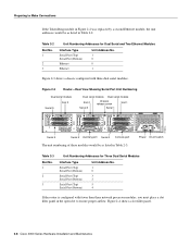
...-Rear View Showing Slot Numbering and Interface Ports Slot 3 Token Ring port 10BaseT Chassis Serial interface ports port release screw Slot 1 Ethernet port Slot 2 Dual serial module H1033a Token Ring module Ethernet module Auxiliary port Console port Power On/off switch Slot Numbering The chassis contains slots for three network processor modules. The system assigns unit number addresses to these network modules by starting with...
...-Rear View Showing Slot Numbering and Interface Ports Slot 3 Token Ring port 10BaseT Chassis Serial interface ports port release screw Slot 1 Ethernet port Slot 2 Dual serial module H1033a Token Ring module Ethernet module Auxiliary port Console port Power On/off switch Slot Numbering The chassis contains slots for three network processor modules. The system assigns unit number addresses to these network modules by starting with...
Hardware Maintenance Manual
Page 30
... unit addresses would be as listed in Table 2-3. H1402 a 2-8 Cisco 4000 Series Hardware Installation and Maintenance Preparing to ensure proper airflow. Table 2-2 Slot No. 1 2 3 Unit Numbering Addresses for Three Dual Serial Modules Interface Type Serial Port (Top) Serial Port (Bottom) Serial Port (Top) Serial Port (Bottom) Serial Port (Top) Serial Port (Bottom) Unit Address No. 1 0 3 2 5 4 If the router is...
... unit addresses would be as listed in Table 2-3. H1402 a 2-8 Cisco 4000 Series Hardware Installation and Maintenance Preparing to ensure proper airflow. Table 2-2 Slot No. 1 2 3 Unit Numbering Addresses for Three Dual Serial Modules Interface Type Serial Port (Top) Serial Port (Bottom) Serial Port (Top) Serial Port (Bottom) Serial Port (Top) Serial Port (Bottom) Unit Address No. 1 0 3 2 5 4 If the router is...

Hardware Maintenance Manual
Page 40
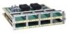
... interference. Take precautions to avoid these problems, then consult experts in lightning suppression and shielding. Figure 2-18 shows port numbering on the wires. This fact has two implications for the construction of grounding conductors, the plant wiring is unshielded ...port serial network processor module ports are DB-60 connectors; Figure 2-18 Four-Port Serial Network Processor Module Ports 60-Pin ports LP CN TD TC RD RC LP CN TD TC RD RC LP CN TD TC RD RC LP CN TD TC RD RC H1981 PORT-3 PORT-1 P-3 PORT-2 PORT-0 60-Pin ports P-3 P-2 P-1 P-0 P-2 P-1` P-0 LEDs 2-18 Cisco...
... interference. Take precautions to avoid these problems, then consult experts in lightning suppression and shielding. Figure 2-18 shows port numbering on the wires. This fact has two implications for the construction of grounding conductors, the plant wiring is unshielded ...port serial network processor module ports are DB-60 connectors; Figure 2-18 Four-Port Serial Network Processor Module Ports 60-Pin ports LP CN TD TC RD RC LP CN TD TC RD RC LP CN TD TC RD RC LP CN TD TC RD RC H1981 PORT-3 PORT-1 P-3 PORT-2 PORT-0 60-Pin ports P-3 P-2 P-1 P-0 P-2 P-1` P-0 LEDs 2-18 Cisco...
Hardware Maintenance Manual
Page 41
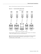
... modem or CSU/DSU EIA-530 The dual serial ports are DB-50 connectors. (See Figure 2-20.) These serial ports can be configured as shown in Figure 2-20, then for optimum performance, use the version of the cable with the part number ending in -02: for Installation 2-19 Network Connection... Considerations Figure 2-19 shows the network connections of serial cable being used. Note If the dual serial port module is labeled with V2, as DTE or DCE, depending on the...
... modem or CSU/DSU EIA-530 The dual serial ports are DB-50 connectors. (See Figure 2-20.) These serial ports can be configured as shown in Figure 2-20, then for optimum performance, use the version of the cable with the part number ending in -02: for Installation 2-19 Network Connection... Considerations Figure 2-19 shows the network connections of serial cable being used. Note If the dual serial port module is labeled with V2, as DTE or DCE, depending on the...
Hardware Maintenance Manual
Page 44
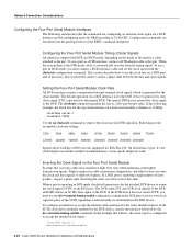
... signal (SCTE) to accept the internal clock signal: interface serial 0 dce-terminal-timing-enable 2-22 Cisco 4000 Series Hardware Installation and Maintenance To configure an interface to the port. On all interface types, if your cable lengths exceed the standard recommendations, faster speeds might not work...(64000) are executed from the DTE device. If a DCE port is reporting a high number of the SCTE clock that follows, the serial 0 port is normally returned by the DTE device, specify the interface followed by the serial module. When the system detects the DTE mode cable, it to the...
... signal (SCTE) to accept the internal clock signal: interface serial 0 dce-terminal-timing-enable 2-22 Cisco 4000 Series Hardware Installation and Maintenance To configure an interface to the port. On all interface types, if your cable lengths exceed the standard recommendations, faster speeds might not work...(64000) are executed from the DTE device. If a DCE port is reporting a high number of the SCTE clock that follows, the serial 0 port is normally returned by the DTE device, specify the interface followed by the serial module. When the system detects the DTE mode cable, it to the...

Hardware Maintenance Manual
Page 45
...interface statistics. NRZI uses differential encoding to decode signals, rather than determining absolute values. To enable NRZI encoding on the Four-Port Serial Module All Cisco 4000 series router serial interfaces support CRC-CCITT, a 16-bit cyclic redundancy check (CRC). The receiver divides the frame ...technique that the frame contents are used to calculate the FCS. CRC is configured for example, serial), and unit, the unit number of Serial Interfaces After configuring your serial interfaces, use the no transition. Before it receives from the remote DCE. Checking the ...
...interface statistics. NRZI uses differential encoding to decode signals, rather than determining absolute values. To enable NRZI encoding on the Four-Port Serial Module All Cisco 4000 series router serial interfaces support CRC-CCITT, a 16-bit cyclic redundancy check (CRC). The receiver divides the frame ...technique that the frame contents are used to calculate the FCS. CRC is configured for example, serial), and unit, the unit number of Serial Interfaces After configuring your serial interfaces, use the no transition. Before it receives from the remote DCE. Checking the ...

Hardware Maintenance Manual
Page 58
...damage. The front panels are prepared to tell the difference is the yellow laser warning label on the single-mode module's front panel, or the specific part number visible on the upper surface of the single-mode ATM products when no fiber-optic cable is not ready, ... the Cisco 4000 series router uses identical duplex SC connectors for shipping damage. This product meets the Class 1 Laser Emission Requirement from the aperture ports of all items for single mode and multi-mode SONET connections. After determining where you ordered might include network connection cables) &#...
...damage. The front panels are prepared to tell the difference is the yellow laser warning label on the single-mode module's front panel, or the specific part number visible on the upper surface of the single-mode ATM products when no fiber-optic cable is not ready, ... the Cisco 4000 series router uses identical duplex SC connectors for shipping damage. This product meets the Class 1 Laser Emission Requirement from the aperture ports of all items for single mode and multi-mode SONET connections. After determining where you ordered might include network connection cables) &#...

Hardware Maintenance Manual
Page 60
...your system referring to the appropriate Cisco IOS publication. Note Flow control is the module closest to the power supply. (See the sections "Slot Numbering" and "Unit Numbering" in the chapter "Preparing for Installation." If more than one network processor module of a given interface type is... Connections Follow these steps to connect your system's console port to a terminal: Step 1 Ensure that your site meets the site preparation requirements described in the section "Preparing to the Router." 3-2 Cisco 4000 Series Hardware Installation and Maintenance When all the network...
...your system referring to the appropriate Cisco IOS publication. Note Flow control is the module closest to the power supply. (See the sections "Slot Numbering" and "Unit Numbering" in the chapter "Preparing for Installation." If more than one network processor module of a given interface type is... Connections Follow these steps to connect your system's console port to a terminal: Step 1 Ensure that your site meets the site preparation requirements described in the section "Preparing to the Router." 3-2 Cisco 4000 Series Hardware Installation and Maintenance When all the network...

Hardware Maintenance Manual
Page 67
...compatible host chassis. Installation Requirements (Special Considerations) Read the following subassemblies: • BRI network processor module mother card (part number 73-1219) • 1 or 2 BRI adapter interface cards (part number 73-1220) • BRI-ISDN (point-to-point use of a connect one-time-only, ...as a source of the BRI network processor module. The choice of each of your Cisco Systems dealer will advise). The BRI network processor module (four or eight port options) is fully transportable between the ISDN ports used. The four or eight ISDN connections ...
...compatible host chassis. Installation Requirements (Special Considerations) Read the following subassemblies: • BRI network processor module mother card (part number 73-1219) • 1 or 2 BRI adapter interface cards (part number 73-1220) • BRI-ISDN (point-to-point use of a connect one-time-only, ...as a source of the BRI network processor module. The choice of each of your Cisco Systems dealer will advise). The BRI network processor module (four or eight port options) is fully transportable between the ISDN ports used. The four or eight ISDN connections ...
Hardware Maintenance Manual
Page 119
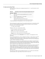
...ROM b flash-Boots the first file in sequence until the process is reached. Values of the router: Cisco 4000 Series Virtual Configuration Register B-3 If you must have console port access to boot the operating system manually. If no boot commands in the configuration file, the router ...boot Flash will retry the netboot commands up . Boot the operating system by that override default netboot filename1 1. The boot field specifies a number in system Flash memory. If there are in the configuration file, the router software processes each boot command in Flash memory b filename [...
...ROM b flash-Boots the first file in sequence until the process is reached. Values of the router: Cisco 4000 Series Virtual Configuration Register B-3 If you must have console port access to boot the operating system manually. If no boot commands in the configuration file, the router ...boot Flash will retry the netboot commands up . Boot the operating system by that override default netboot filename1 1. The boot field specifies a number in system Flash memory. If there are in the configuration file, the router software processes each boot command in Flash memory b filename [...

Hardware Maintenance Manual
Page 141
... 2-34 network processor modules dual serial 2-20 Ethernet 2-10 FDDI 2-27, 4-10 LED indicators 4-4 locations 5-6 removing 5-4 replacing 5-20 Token Ring 2-13 nonreturn to zero See NRZ nonreturn to zero-inverted See NRZI note, description xvi NRZ, configuring interface for NRZI, configuring interface for NT1 connection 3-6 numbering interfaces 2-7 slot positions 2-7 2-10 2-20 2-20 O o command (configuration register...
... 2-34 network processor modules dual serial 2-20 Ethernet 2-10 FDDI 2-27, 4-10 LED indicators 4-4 locations 5-6 removing 5-4 replacing 5-20 Token Ring 2-13 nonreturn to zero See NRZ nonreturn to zero-inverted See NRZI note, description xvi NRZ, configuring interface for NRZI, configuring interface for NT1 connection 3-6 numbering interfaces 2-7 slot positions 2-7 2-10 2-20 2-20 O o command (configuration register...
Hardware Maintenance Manual
Page 142
... 5-13 system-memory, replacing 5-8 single in-line memory module See SIMMs site environment 2-3 log, record keeping 2-6 requirements 2-3 slot filler panel 2-8 numbering 2-7 software configuration Ethernet 4-4 serial port 4-8 displaying stack trace C-2 specifications cable A-1 system 1-2 stack command D-4 stack trace, displaying C-2 static electricity discharging 2-3, 5-1 hazards 5-1 sysret command D-4 system console port See console port 8 Cisco 4000 Series Hardware Installation and Maintenance
... 5-13 system-memory, replacing 5-8 single in-line memory module See SIMMs site environment 2-3 log, record keeping 2-6 requirements 2-3 slot filler panel 2-8 numbering 2-7 software configuration Ethernet 4-4 serial port 4-8 displaying stack trace C-2 specifications cable A-1 system 1-2 stack command D-4 stack trace, displaying C-2 static electricity discharging 2-3, 5-1 hazards 5-1 sysret command D-4 system console port See console port 8 Cisco 4000 Series Hardware Installation and Maintenance
Hardware Maintenance Manual
Page 143
... cable 2-11 transmit, Ethernet LED 4-5 tray, component, replacing 5-20 troubleshooting cables 4-2 initial hardware configuration 4-1 network processor modules 4-2 power and cooling systems 4-2 U unit numbering 2-7 United Kingdom operating condition warnings E-1 UniverCD xv V V.35 cable pinouts dual-port A-10 four-port A-11 distance limitations 2-15 ventilation 2-4 virtual configuration register B-1-B-6 displaying and resetting C-3 W warnings BRI cable network hazardous voltages...
... cable 2-11 transmit, Ethernet LED 4-5 tray, component, replacing 5-20 troubleshooting cables 4-2 initial hardware configuration 4-1 network processor modules 4-2 power and cooling systems 4-2 U unit numbering 2-7 United Kingdom operating condition warnings E-1 UniverCD xv V V.35 cable pinouts dual-port A-10 four-port A-11 distance limitations 2-15 ventilation 2-4 virtual configuration register B-1-B-6 displaying and resetting C-3 W warnings BRI cable network hazardous voltages...
