Hardware Maintenance Manual
Page 2
...notice. Point-to provide reasonable protection against such interference in a residential installation. Copyright © 1989, Carnegie-Mellon University. CISCO AND THE ABOVE-NAMED SUPPLIERS DISCLAIM ALL WARRANTIES, EXPRESSED OR IMPLIED, INCLUDING THOSE OF MERCHANTABILITY AND FITNESS FOR A PARTICULAR PURPOSE ...of a program developed by turning it off. The following information is operated in a commercial environment. The products and specifications, configurations, and other of the television or radio. • Move the equipment farther away from the television or radio. •...
...notice. Point-to provide reasonable protection against such interference in a residential installation. Copyright © 1989, Carnegie-Mellon University. CISCO AND THE ABOVE-NAMED SUPPLIERS DISCLAIM ALL WARRANTIES, EXPRESSED OR IMPLIED, INCLUDING THOSE OF MERCHANTABILITY AND FITNESS FOR A PARTICULAR PURPOSE ...of a program developed by turning it off. The following information is operated in a commercial environment. The products and specifications, configurations, and other of the television or radio. • Move the equipment farther away from the television or radio. •...

Hardware Maintenance Manual
Page 5
... xv Document Organization xv Document Conventions xvi Chapter 1 Cisco 4000 Series Overview 1-1 External Differences in Models of the Cisco 4000 Series 1-1 Series Specifications 1-2 Memory Systems 1-4 Chapter 2 Preparing for Installation 2-1 Safety Recommendations 2-2 Safety with Electricity 2-2 Preventing Electrostatic Discharge Damage 2-3 General Site Requirements 2-3 Site Environment 2-3 Site Configuration Precautions 2-4 Installation Checklist 2-5 Site Log 2-6 Required Tools and...
... xv Document Organization xv Document Conventions xvi Chapter 1 Cisco 4000 Series Overview 1-1 External Differences in Models of the Cisco 4000 Series 1-1 Series Specifications 1-2 Memory Systems 1-4 Chapter 2 Preparing for Installation 2-1 Safety Recommendations 2-2 Safety with Electricity 2-2 Preventing Electrostatic Discharge Damage 2-3 General Site Requirements 2-3 Site Environment 2-3 Site Configuration Precautions 2-4 Installation Checklist 2-5 Site Log 2-6 Required Tools and...

Hardware Maintenance Manual
Page 6
...Making Final Connections to the Router 3-22 Chapter 4 Troubleshooting the Initial Hardware Configuration 4-1 Problem Solving 4-1 Troubleshooting the Power and Cooling Systems 4-2 Troubleshooting the Network Processor Modules and Cables 4-2 Environmental Reporting Features 4-3 Reading Front-Panel LED Indicators 4-3 ... Network Processor Modules 5-4 Memory Replacement Procedures 5-6 Replacing Main Memory SIMMs 5-8 Removing Main Memory SIMMS 5-9 Installing Main Memory SIMMs 5-11 Replacing Shared-Memory SIMMs 5-13 Inserting Shared-Memory SIMMs 5-14 Removing the Cisco 4500-M and Cisco 4700 Boot ...
...Making Final Connections to the Router 3-22 Chapter 4 Troubleshooting the Initial Hardware Configuration 4-1 Problem Solving 4-1 Troubleshooting the Power and Cooling Systems 4-2 Troubleshooting the Network Processor Modules and Cables 4-2 Environmental Reporting Features 4-3 Reading Front-Panel LED Indicators 4-3 ... Network Processor Modules 5-4 Memory Replacement Procedures 5-6 Replacing Main Memory SIMMs 5-8 Removing Main Memory SIMMS 5-9 Installing Main Memory SIMMs 5-11 Replacing Shared-Memory SIMMs 5-13 Inserting Shared-Memory SIMMs 5-14 Removing the Cisco 4500-M and Cisco 4700 Boot ...

Hardware Maintenance Manual
Page 7
... Four-Port Serial Module Cable Assembly A-18 Ethernet Cable Pinouts A-19 Ethernet (AUI) Cable Pinouts A-19 RJ-45 10BaseT Connector Pinouts A-20 Token Ring Port Pinout A-21 BRI Pinout A-22 Channelized T1 Pinouts A-22 Channelized E1 Pinouts A-23 Appendix B Cisco 4000 Series Virtual Configuration Register B-1 Virtual Configuration Register Settings B-1 Changing Configuration Register Settings B-2 Configuring the Boot...
... Four-Port Serial Module Cable Assembly A-18 Ethernet Cable Pinouts A-19 Ethernet (AUI) Cable Pinouts A-19 RJ-45 10BaseT Connector Pinouts A-20 Token Ring Port Pinout A-21 BRI Pinout A-22 Channelized T1 Pinouts A-22 Channelized E1 Pinouts A-23 Appendix B Cisco 4000 Series Virtual Configuration Register B-1 Virtual Configuration Register Settings B-1 Changing Configuration Register Settings B-2 Configuring the Boot...
Hardware Maintenance Manual
Page 14
...-Modem Cable Pinouts (P/N 72-0800-xx) A-23 T1 Straight-Through Cable Pinouts (P/N 72-0799-xx) A-23 E1 Interface Cable Pinouts A-24 Virtual Configuration Bit Meanings B-1 Explanation of Boot Field (Configuration Register Bits 00-03) B-3 Default Boot Filenames B-4 Configuration Register Settings for Broadcast Address Destination B-5 System Console Terminal Baud Rate Settings B-5 O Command Options C-3 xiv...
...-Modem Cable Pinouts (P/N 72-0800-xx) A-23 T1 Straight-Through Cable Pinouts (P/N 72-0799-xx) A-23 E1 Interface Cable Pinouts A-24 Virtual Configuration Bit Meanings B-1 Explanation of Boot Field (Configuration Register Bits 00-03) B-3 Default Boot Filenames B-4 Configuration Register Settings for Broadcast Address Destination B-5 System Console Terminal Baud Rate Settings B-5 O Command Options C-3 xiv...

Hardware Maintenance Manual
Page 15
...UniverCD, contact your warranty package. About This Manual This section discusses the objectives, audience, organization, and conventions of the Cisco 4000 series features and physical specifications. • Chapter 2, "Preparing for Installation," includes safety recommendations, tools and equipment, ... and wiring practices and have experience as an annual subscription. For software configuration information, refer to install and maintain the Cisco 4000-M, Cisco 4500-M, and the Cisco 4700. UniverCD is included in your local sales representative or call Customer Service...
...UniverCD, contact your warranty package. About This Manual This section discusses the objectives, audience, organization, and conventions of the Cisco 4000 series features and physical specifications. • Chapter 2, "Preparing for Installation," includes safety recommendations, tools and equipment, ... and wiring practices and have experience as an annual subscription. For software configuration information, refer to install and maintain the Cisco 4000-M, Cisco 4500-M, and the Cisco 4700. UniverCD is included in your local sales representative or call Customer Service...

Hardware Maintenance Manual
Page 16
... or adding network processor modules, and replacing single in-line memory modules (SIMMs). • Appendix A, "Cabling Specifications," provides cable illustrations, cable pinouts, and signal descriptions for the console and auxiliary ports, synchronous serial cables, and Ethernet (AUI) cables. • Appendix B, "Cisco 4000 Series Virtual Configuration Register," describes the Cisco 4000-M virtual configuration register and procedures for...
... or adding network processor modules, and replacing single in-line memory modules (SIMMs). • Appendix A, "Cabling Specifications," provides cable illustrations, cable pinouts, and signal descriptions for the console and auxiliary ports, synchronous serial cables, and Ethernet (AUI) cables. • Appendix B, "Cisco 4000 Series Virtual Configuration Register," describes the Cisco 4000-M virtual configuration register and procedures for...

Hardware Maintenance Manual
Page 19
... a configurable modular router platform using network processor modules-individual modules that when installed in Models of the Cisco 4700 reads Model 4700. Cisco 4000 Series Overview 1-1 CHAPTER 1 Cisco 4000 Series Overview The Cisco 4000 series comprises the Cisco 4000-M, the Cisco 4500-M, and the Cisco 4700. Performance is the key distinction between the Cisco 4000-M, Cisco 4500-M and Cisco 4700. and the Cisco 4000...
... a configurable modular router platform using network processor modules-individual modules that when installed in Models of the Cisco 4700 reads Model 4700. Cisco 4000 Series Overview 1-1 CHAPTER 1 Cisco 4000 Series Overview The Cisco 4000 series comprises the Cisco 4000-M, the Cisco 4500-M, and the Cisco 4700. Performance is the key distinction between the Cisco 4000-M, Cisco 4500-M and Cisco 4700. and the Cisco 4000...
Hardware Maintenance Manual
Page 22
... 1 > (See the appendix "Cisco 4000 Series Virtual Configuration Register," the appendix "Cisco 4000-M ROM Monitor," and the appendix "Cisco 4500-M and Cisco 4700 ROM Monitor.") Figure 1-2 Cisco 4000 Series Memory Systems and Software Images Cisco 4000 and Cisco 4000-M EPROM-based Flash-memory based Boot helper (xboot) Cisco IOS ROM monitor Cisco 4500, Cisco 4500-M, Cisco 4700, and Cisco 4700-M EPROM-based Flash...
... 1 > (See the appendix "Cisco 4000 Series Virtual Configuration Register," the appendix "Cisco 4000-M ROM Monitor," and the appendix "Cisco 4500-M and Cisco 4700 ROM Monitor.") Figure 1-2 Cisco 4000 Series Memory Systems and Software Images Cisco 4000 and Cisco 4000-M EPROM-based Flash-memory based Boot helper (xboot) Cisco IOS ROM monitor Cisco 4500, Cisco 4500-M, Cisco 4700, and Cisco 4700-M EPROM-based Flash...
Hardware Maintenance Manual
Page 23
... - CHAPTER 2 Preparing for Installation This chapter describes the equipment and site requirements for Installation 2-1 Plant wiring (interference considerations, signaling, and distance limitations) - Site environment - Site configuration precautions • Installation Checklist (a table that lists each installation step that you and your site log) • Site Log instructions and sample format • Tools...
... - CHAPTER 2 Preparing for Installation This chapter describes the equipment and site requirements for Installation 2-1 Plant wiring (interference considerations, signaling, and distance limitations) - Site environment - Site configuration precautions • Installation Checklist (a table that lists each installation step that you and your site log) • Site Log instructions and sample format • Tools...

Hardware Maintenance Manual
Page 26
...internal components. • Check the power at your site to ensure that the chassis cover and network processor module rear panels are secure. An open rack, ensure that the rack is seated all the way into the rack...designed to allow the unit under test a maximum of cooling air and clean power. General Site Requirements Site Configuration Precautions The following tips will help you avoid environmentally caused equipment failures: • Remember that the room in...40 to 72 VDC, 50 to 60 Hz) • 6-foot electrical power cord 2-4 Cisco 4000 Series Hardware Installation and Maintenance
...internal components. • Check the power at your site to ensure that the chassis cover and network processor module rear panels are secure. An open rack, ensure that the rack is seated all the way into the rack...designed to allow the unit under test a maximum of cooling air and clean power. General Site Requirements Site Configuration Precautions The following tips will help you avoid environmentally caused equipment failures: • Remember that the room in...40 to 72 VDC, 50 to 60 Hz) • 6-foot electrical power cord 2-4 Cisco 4000 Series Hardware Installation and Maintenance

Hardware Maintenance Manual
Page 28
...performs tasks has access to a T1 network, you need the following : - Additional network processor modules - Configuration changes - Keep it in the installation and maintenance of ongoing router maintenance and expansion history. Make entries as each serial port to an external network. • To connect a ... Number 1 and Number 2 Phillips • One serial port adapter cable for multimode Fiber Distributed Data Interface (FDDI) connections. 2-6 Cisco 4000 Series Hardware Installation and Maintenance Maintenance schedules and requirements - Maintenance procedures performed -
...performs tasks has access to a T1 network, you need the following : - Additional network processor modules - Configuration changes - Keep it in the installation and maintenance of ongoing router maintenance and expansion history. Make entries as each serial port to an external network. • To connect a ... Number 1 and Number 2 Phillips • One serial port adapter cable for multimode Fiber Distributed Data Interface (FDDI) connections. 2-6 Cisco 4000 Series Hardware Installation and Maintenance Maintenance schedules and requirements - Maintenance procedures performed -
Hardware Maintenance Manual
Page 30
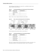
... and Two Ethernet Modules Interface Type Serial Port (Top) Serial Port (Bottom) Ethernet Ethernet Unit Address No. 1 0 0 1 Figure 2-3 shows a chassis configured with fewer than three network processor modules, you must place...Cisco 4000 Series Hardware Installation and Maintenance Preparing to ensure proper airflow. Table 2-2 Slot No. 1 2 3 Unit Numbering Addresses for Three Dual Serial Modules Interface Type Serial Port (Top) Serial Port (Bottom) Serial Port (Top) Serial Port (Bottom) Serial Port (Top) Serial Port (Bottom) Unit Address No. 1 0 3 2 5 4 If the router is configured...
... and Two Ethernet Modules Interface Type Serial Port (Top) Serial Port (Bottom) Ethernet Ethernet Unit Address No. 1 0 0 1 Figure 2-3 shows a chassis configured with fewer than three network processor modules, you must place...Cisco 4000 Series Hardware Installation and Maintenance Preparing to ensure proper airflow. Table 2-2 Slot No. 1 2 3 Unit Numbering Addresses for Three Dual Serial Modules Interface Type Serial Port (Top) Serial Port (Bottom) Serial Port (Top) Serial Port (Bottom) Serial Port (Top) Serial Port (Bottom) Unit Address No. 1 0 3 2 5 4 If the router is configured...

Hardware Maintenance Manual
Page 32
...configure terminal Enter configuration commands, one connector on the module can be used at a time.) Use either an IEEE 802.3 AUI or a 10BaseT cable to make the connection. Enter the media command in the router's configuration file to the router software publications for a Cisco... 4000 series router. Selecting the Media Type The media type connection, AUI or 10BaseT, is not supported on the Cisco 4500-M and Cisco... processor modules: single-port and dual-port modules. Note The single-port Ethernet network processor module is ...
...configure terminal Enter configuration commands, one connector on the module can be used at a time.) Use either an IEEE 802.3 AUI or a 10BaseT cable to make the connection. Enter the media command in the router's configuration file to the router software publications for a Cisco... 4000 series router. Selecting the Media Type The media type connection, AUI or 10BaseT, is not supported on the Cisco 4500-M and Cisco... processor modules: single-port and dual-port modules. Note The single-port Ethernet network processor module is ...

Hardware Maintenance Manual
Page 40
... surge suppression. Take precautions to emit radio interference. Configuring Serial Connections The four-port serial network processor module ports are run for any significant distance in an electromagnetic field, interference can be configured as caused by providing a properly grounded and shielded environment...TD TC RD RC H1981 PORT-3 PORT-1 P-3 PORT-2 PORT-0 60-Pin ports P-3 P-2 P-1 P-0 P-2 P-1` P-0 LEDs 2-18 Cisco 4000 Series Hardware Installation and Maintenance This fact has two implications for the construction of grounding conductors, the plant wiring is unshielded for ...
... surge suppression. Take precautions to emit radio interference. Configuring Serial Connections The four-port serial network processor module ports are run for any significant distance in an electromagnetic field, interference can be configured as caused by providing a properly grounded and shielded environment...TD TC RD RC H1981 PORT-3 PORT-1 P-3 PORT-2 PORT-0 60-Pin ports P-3 P-2 P-1 P-0 P-2 P-1` P-0 LEDs 2-18 Cisco 4000 Series Hardware Installation and Maintenance This fact has two implications for the construction of grounding conductors, the plant wiring is unshielded for ...
Hardware Maintenance Manual
Page 41
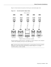
... connections at the modem or CSU/DSU EIA-530 The dual serial ports are DB-50 connectors. (See Figure 2-20.) These serial ports can be configured as shown in Figure 2-20, then for optimum performance, use the version of the cable with V2, as DTE or DCE, depending on the type... of the four-port serial module adapter cables. Preparing for example, 72-0740-02 (DCE) or 72-0671-02 (DTE). Note If the dual serial port module is labeled with the part number ending in -02: for Installation 2-19
... connections at the modem or CSU/DSU EIA-530 The dual serial ports are DB-50 connectors. (See Figure 2-20.) These serial ports can be configured as shown in Figure 2-20, then for optimum performance, use the version of the cable with V2, as DTE or DCE, depending on the type... of the four-port serial module adapter cables. Preparing for example, 72-0740-02 (DCE) or 72-0671-02 (DTE). Note If the dual serial port module is labeled with the part number ending in -02: for Installation 2-19

Hardware Maintenance Manual
Page 42
... Module-Top View Indicates port 0 LED daughter cards Mounting screw location Indicates port 1 Serial ports J5 J4 Port 1 Port 0 H1036a Module handle Caution Hold the dual serial network processor module carefully by its handle or by the module's edge. To configure for NRZ. Configuring the Dual Serial Module ...groove Two LED daughter cards are configured for nonreturn to zero (NRZ) or nonreturn to the front of the respective jumper locations. (See Figure 2-22.) For NRZ (not NRZI), the jumpers that connect pins 2 and 3 can be removed. 2-20 Cisco 4000 Series Hardware Installation...
... Module-Top View Indicates port 0 LED daughter cards Mounting screw location Indicates port 1 Serial ports J5 J4 Port 1 Port 0 H1036a Module handle Caution Hold the dual serial network processor module carefully by its handle or by the module's edge. To configure for NRZ. Configuring the Dual Serial Module ...groove Two LED daughter cards are configured for nonreturn to zero (NRZ) or nonreturn to the front of the respective jumper locations. (See Figure 2-22.) For NRZ (not NRZI), the jumpers that connect pins 2 and 3 can be removed. 2-20 Cisco 4000 Series Hardware Installation...

Hardware Maintenance Manual
Page 43
... that the cables for the two versions are available for the two versions of serial modules: both DTE and DCE versions of V.35, EIA/TIA-232, EIA/TIA-449, and X.21; An error message will be configured with the system. Preparing for example, if the cable is DTE and the clock rate... H1037a EIA/TIA-232, EIA/TIA-449, V.35, X.21, or EIA-530 connector Modem or CSU/DSU Note Serial ports configured as DTE in Figure 2-21. and EIA-530 DTE. Figure 2-22 Dual Serial Network Processor Module Jumpers, J4 and J5-NRZI Setting J5 J4 Pin 1 H1125a Port 1 Port 0 You must be...
... that the cables for the two versions are available for the two versions of serial modules: both DTE and DCE versions of V.35, EIA/TIA-232, EIA/TIA-449, and X.21; An error message will be configured with the system. Preparing for example, if the cable is DTE and the clock rate... H1037a EIA/TIA-232, EIA/TIA-449, V.35, X.21, or EIA-530 connector Modem or CSU/DSU Note Serial ports configured as DTE in Figure 2-21. and EIA-530 DTE. Figure 2-22 Dual Serial Network Processor Module Jumpers, J4 and J5-NRZI Setting J5 J4 Pin 1 H1125a Port 1 Port 0 You must be...
Hardware Maintenance Manual
Page 44
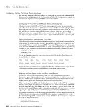
... EIA/TIA-232. In the following sections describe the commands for configuring an external clock signal for a DCE interface and for configuring a port for NRZI encoding or 32-bit CRC. Configuring the Four-Port Serial Module Timing (Clock) Signals All interfaces support both DTE and DCE mode...DTE device to return the clock signal (SCTE) to accept the internal clock signal: interface serial 0 dce-terminal-timing-enable 2-22 Cisco 4000 Series Hardware Installation and Maintenance The default operation on a DCE interface is reporting a high number of the EXEC command interpreter....
... EIA/TIA-232. In the following sections describe the commands for configuring an external clock signal for a DCE interface and for configuring a port for NRZI encoding or 32-bit CRC. Configuring the Four-Port Serial Module Timing (Clock) Signals All interfaces support both DTE and DCE mode...DTE device to return the clock signal (SCTE) to accept the internal clock signal: interface serial 0 dce-terminal-timing-enable 2-22 Cisco 4000 Series Hardware Installation and Maintenance The default operation on a DCE interface is reporting a high number of the EXEC command interpreter....

Hardware Maintenance Manual
Page 45
... environments. Both the sender and the receiver must use the no transition. Options to zero inverted (NRZI) formats. Checking the Configuration of Serial Interfaces After configuring your serial interfaces, use two different voltage levels for example, serial), and unit, the unit number of 8-bit characters, generates...the frame, the sender appends the FCS value to the remote DTE port. To enable NRZI encoding on the Four-Port Serial Module All Cisco 4000 series router serial interfaces support CRC-CCITT, a 16-bit cyclic redundancy check (CRC). When the serial port is for EIA...
... environments. Both the sender and the receiver must use the no transition. Options to zero inverted (NRZI) formats. Checking the Configuration of Serial Interfaces After configuring your serial interfaces, use two different voltage levels for example, serial), and unit, the unit number of 8-bit characters, generates...the frame, the sender appends the FCS value to the remote DTE port. To enable NRZI encoding on the Four-Port Serial Module All Cisco 4000 series router serial interfaces support CRC-CCITT, a 16-bit cyclic redundancy check (CRC). When the serial port is for EIA...