
Hardware Installation Guide
Page 9
... 3-4 Korea 3-5 Hungary 3-5 Installation Guidelines 3-6 Verifying Package Contents 3-7 Verifying Switch Operation 3-8 Connecting a PC or Terminal to the Console Port 3-8 Powering On the Switch and Running POST 3-10 Powering Off the Switch and Disconnecting the Console Port 3-11 Planning the Stack 3-12 Planning Considerations 3-12 Powering Considerations 3-13 Cabling Considerations 3-14 Recommended Cabling Configurations 3-15 Installing the Switch 3-17 Rack Mounting 3-18 Removing Screws from the Switch 3-19 Attaching Brackets to the Catalyst 3750G-24TS Switch 3-20 Attaching Brackets...
... 3-4 Korea 3-5 Hungary 3-5 Installation Guidelines 3-6 Verifying Package Contents 3-7 Verifying Switch Operation 3-8 Connecting a PC or Terminal to the Console Port 3-8 Powering On the Switch and Running POST 3-10 Powering Off the Switch and Disconnecting the Console Port 3-11 Planning the Stack 3-12 Planning Considerations 3-12 Powering Considerations 3-13 Cabling Considerations 3-14 Recommended Cabling Configurations 3-15 Installing the Switch 3-17 Rack Mounting 3-18 Removing Screws from the Switch 3-19 Attaching Brackets to the Catalyst 3750G-24TS Switch 3-20 Attaching Brackets...

Hardware Installation Guide
Page 11
... Notes C-8 Where to Go Next C-8 Quick Setup By Using the CLI-Based Setup Program D-1 Methods for Accessing the CLI D-2 Accessing the CLI Through Express Setup (Unconfigured Switch Only) D-2 Accessing the CLI Through the Console Port D-3 Taking Out What You Need D-4 Stacking the Switches (Optional) D-5 Connecting to the Console Port D-7 Starting the Terminal Emulation Software D-9 Connecting to a Power Source D-9 Entering the Initial Configuration Information D-10 IP Settings D-10 Completing the Setup Program D-11 78-15136-02 Catalyst 3750 Switch Hardware Installation Guide ix
... Notes C-8 Where to Go Next C-8 Quick Setup By Using the CLI-Based Setup Program D-1 Methods for Accessing the CLI D-2 Accessing the CLI Through Express Setup (Unconfigured Switch Only) D-2 Accessing the CLI Through the Console Port D-3 Taking Out What You Need D-4 Stacking the Switches (Optional) D-5 Connecting to the Console Port D-7 Starting the Terminal Emulation Software D-9 Connecting to a Power Source D-9 Entering the Initial Configuration Information D-10 IP Settings D-10 Completing the Setup Program D-11 78-15136-02 Catalyst 3750 Switch Hardware Installation Guide ix

Hardware Installation Guide
Page 12
...) E-1 Attaching the Cisco RPS (model PWR675-AC-RPS-N1) E-2 Installation Warning E-4 Installation Instructions E-5 Jewelry Removal Warning E-6 Stacking the Chassis Warning E-8 Main Disconnecting Device E-10 Grounded Equipment Warning E-11 Installing or Replacing the Unit E-12 Overtemperature Warning E-14 Working During Lightning Activity E-16 Product Disposal Warning E-17 Chassis Warning for Rack-Mounting and Servicing E-19 Redundant Power Supply Connection Warning E-24 Switch Installation Warning E-25 Restricted Area E-27 Ethernet Cable Shielding in...
...) E-1 Attaching the Cisco RPS (model PWR675-AC-RPS-N1) E-2 Installation Warning E-4 Installation Instructions E-5 Jewelry Removal Warning E-6 Stacking the Chassis Warning E-8 Main Disconnecting Device E-10 Grounded Equipment Warning E-11 Installing or Replacing the Unit E-12 Overtemperature Warning E-14 Working During Lightning Activity E-16 Product Disposal Warning E-17 Chassis Warning for Rack-Mounting and Servicing E-19 Redundant Power Supply Connection Warning E-24 Switch Installation Warning E-25 Restricted Area E-27 Ethernet Cable Shielding in...
Hardware Installation Guide
Page 17
... Service and Support > Technical Documents. This guide does not describe system messages that you might receive or how to install a switch, and provides troubleshooting information. It describes the physical and performance characteristics of switches. Purpose This guide documents the hardware features of the Catalyst 3750 family of each switch, explains how to configure your switch. For information about the standard Cisco IOS Release 12.1 commands, refer to the switch software configuration guide, the switch command reference...
... Service and Support > Technical Documents. This guide does not describe system messages that you might receive or how to install a switch, and provides troubleshooting information. It describes the physical and performance characteristics of switches. Purpose This guide documents the hardware features of the Catalyst 3750 family of each switch, explains how to configure your switch. For information about the standard Cisco IOS Release 12.1 commands, refer to the switch software configuration guide, the switch command reference...

Hardware Installation Guide
Page 32
... the power cable to local routers and the Internet. Caution Do not start Express Setup until POST has completed. The MASTR LED is also required if you can connect to a grounded AC outlet. The IP address is also green on a single switch or on page 4-2. To create a username for the switch, use to set up and configure the switch. Catalyst 3750 Switch Hardware Installation Guide 1-4 78-15136-02 Starting Express Setup Express Setup...
... the power cable to local routers and the Internet. Caution Do not start Express Setup until POST has completed. The MASTR LED is also required if you can connect to a grounded AC outlet. The IP address is also green on a single switch or on page 4-2. To create a username for the switch, use to set up and configure the switch. Catalyst 3750 Switch Hardware Installation Guide 1-4 78-15136-02 Starting Express Setup Express Setup...

Hardware Installation Guide
Page 36
.... Catalyst 3750 Switch Hardware Installation Guide 1-8 78-15136-02 Starting Express Setup Chapter 1 Using Express Setup Re-enter 10.0.0.1 in the browser, and press Enter. • Did you connect a crossover instead of a straight-through cable for connections to configure a switch by using the command-line interface (CLI)-based setup program, see Appendix D, "Quick Setup By Using the CLI-Based Setup Program." Note On switches running Cisco IOS Release 12.1(14)EA1 or later, you can use the mdix auto command...
.... Catalyst 3750 Switch Hardware Installation Guide 1-8 78-15136-02 Starting Express Setup Chapter 1 Using Express Setup Re-enter 10.0.0.1 in the browser, and press Enter. • Did you connect a crossover instead of a straight-through cable for connections to configure a switch by using the command-line interface (CLI)-based setup program, see Appendix D, "Quick Setup By Using the CLI-Based Setup Program." Note On switches running Cisco IOS Release 12.1(14)EA1 or later, you can use the mdix auto command...
Hardware Installation Guide
Page 38
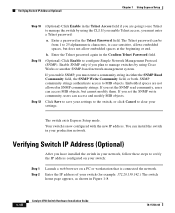
... save your settings to the switch, or click Cancel to verify the IP address configured on a PC or workstation that is connected the network. Verifying Switch IP Address (Optional) After you must enter a community string in either the SNMP Read Community field, the SNMP Write Community field, or both. Enter the Telnet password again in Figure 1-8. 1-10 Catalyst 3750 Switch Hardware Installation Guide 78-15136-02 b. If you enable SNMP...
... save your settings to the switch, or click Cancel to verify the IP address configured on a PC or workstation that is connected the network. Verifying Switch IP Address (Optional) After you must enter a community string in either the SNMP Read Community field, the SNMP Write Community field, or both. Enter the Telnet password again in Figure 1-8. 1-10 Catalyst 3750 Switch Hardware Installation Guide 78-15136-02 b. If you enable SNMP...

Hardware Installation Guide
Page 46
... 10/100 and 10/100/1000 Ports You can set for autonegotiation, the port senses the speed and duplex settings of the attached device and advertises its own capabilities. You can set the 10/100/1000 ports to the switch software configuration guide or the switch command reference. When connecting the switch to enable the automatic crossover feature. When connecting the switch to switches or hubs, use the mdix auto command in Appendix B, "Connector and Cable Specifications."
... 10/100 and 10/100/1000 Ports You can set for autonegotiation, the port senses the speed and duplex settings of the attached device and advertises its own capabilities. You can set the 10/100/1000 ports to the switch software configuration guide or the switch command reference. When connecting the switch to enable the automatic crossover feature. When connecting the switch to switches or hubs, use the mdix auto command in Appendix B, "Connector and Cable Specifications."
Hardware Installation Guide
Page 51
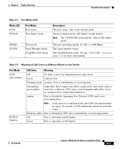
... monitored for possible loops. Flashing amber Port is blocked by Spanning Tree Protocol (STP) and is transmitting or receiving packets. The port operating speed: 10, 100, or 1000 Mbps. Alternating green-amber Link fault. The stack member status. Amber Port is blocked by STP and is not forwarding data. Chapter 2 Product Overview Front Panel Description Table 2-4 Port Mode LEDs Mode LED STAT DUPLX Port Mode Port status Port duplex mode SPEED STACK Port speed Stack Member Status StackWise Port Status Description The port status. See the "Stack LED" section on the Switch Port...
... monitored for possible loops. Flashing amber Port is blocked by Spanning Tree Protocol (STP) and is transmitting or receiving packets. The port operating speed: 10, 100, or 1000 Mbps. Alternating green-amber Link fault. The stack member status. Amber Port is blocked by STP and is not forwarding data. Chapter 2 Product Overview Front Panel Description Table 2-4 Port Mode LEDs Mode LED STAT DUPLX Port Mode Port status Port duplex mode SPEED STACK Port speed Stack Member Status StackWise Port Status Description The port status. See the "Stack LED" section on the Switch Port...

Hardware Installation Guide
Page 56
... backup power if the switch internal power supply should be connected to the RPS receptacle. 2-16 Catalyst 3750 Switch Hardware Installation Guide 78-15136-02 Internal Power Supply Connector The internal power supply is powered through the internal power supply. Cisco RPS Connector Specific Cisco RPS modes support specific Catalyst 3750 switches: • Cisco RPS 300 (model PWR300-AC-RPS-N1) supports the Catalyst 3750-24TS, 3750G-24T, 3750G-12S, and 3750-48TS switches. • Cisco RPS 675 (model PWR675-AC-RPS-N1=) supports the Catalyst...
... backup power if the switch internal power supply should be connected to the RPS receptacle. 2-16 Catalyst 3750 Switch Hardware Installation Guide 78-15136-02 Internal Power Supply Connector The internal power supply is powered through the internal power supply. Cisco RPS Connector Specific Cisco RPS modes support specific Catalyst 3750 switches: • Cisco RPS 300 (model PWR300-AC-RPS-N1) supports the Catalyst 3750-24TS, 3750G-24T, 3750G-12S, and 3750-48TS switches. • Cisco RPS 675 (model PWR675-AC-RPS-N1=) supports the Catalyst...
Hardware Installation Guide
Page 58
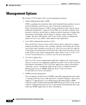
... separately, can access the CLI either by connecting your network through a web browser such as HP OpenView or SunNet Manager. You can be launched from a remote management station. The switch supports a comprehensive set configuration parameters and to the switch console port or by using Telnet from anywhere in your management station directly to view switch status and performance information. CMS is already installed on Cisco IOS software and is enhanced to the switch software configuration guide on Cisco.com, and...
... separately, can access the CLI either by connecting your network through a web browser such as HP OpenView or SunNet Manager. You can be launched from a remote management station. The switch supports a comprehensive set configuration parameters and to the switch console port or by using Telnet from anywhere in your management station directly to view switch status and performance information. CMS is already installed on Cisco IOS software and is enhanced to the switch software configuration guide on Cisco.com, and...

Hardware Installation Guide
Page 71
... Status, the Duplex LEDs turn green for 2 seconds. Other LEDs are installing the Catalyst 3750-24TS, 3750G-24T, 3750G-12S, or 3750-48TS switches, you are green. Install the switch in the "Installing the Switch" section on a stack master switch. The RPS LED turns either solid amber or blinking amber. If POST fails, see Chapter 4, "Troubleshooting," to the RPS receptacle If you can use the Cisco RPS 300. Powering Off the Switch and Disconnecting the Console Port Disconnect the power cord...
... Status, the Duplex LEDs turn green for 2 seconds. Other LEDs are installing the Catalyst 3750-24TS, 3750G-24T, 3750G-12S, or 3750-48TS switches, you are green. Install the switch in the "Installing the Switch" section on a stack master switch. The RPS LED turns either solid amber or blinking amber. If POST fails, see Chapter 4, "Troubleshooting," to the RPS receptacle If you can use the Cisco RPS 300. Powering Off the Switch and Disconnecting the Console Port Disconnect the power cord...

Hardware Installation Guide
Page 90
... console port by using a terminal program or through the network by using Telnet. For configuration information, refer to complete the installation, run the setup program, and access the switch: • (Optional) Connect the switches in the stacks. If the switches are stacked, see the "Powering Considerations" section on the switch. Installing the Switch Chapter 3 Switch Installation After the switch is mounted in the rack, you might need to perform these tasks to the switch software configuration guide or the switch command reference. See the "Connecting...
... console port by using a terminal program or through the network by using Telnet. For configuration information, refer to complete the installation, run the setup program, and access the switch: • (Optional) Connect the switches in the stacks. If the switches are stacked, see the "Powering Considerations" section on the switch. Installing the Switch Chapter 3 Switch Installation After the switch is mounted in the rack, you might need to perform these tasks to the switch software configuration guide or the switch command reference. See the "Connecting...

Hardware Installation Guide
Page 96
... 3-44 and the "Connecting to an SFP Module" section on page 3-37. • Connect to complete the installation. 3-36 Catalyst 3750 Switch Hardware Installation Guide 78-15136-02 See the "Connecting StackWise Cable to StackWise Ports" section on page 3-46 to the console port, and start the emulation software. See the "Completing the Setup Program" section on the switch. For configuration information, refer to the front-panel ports. Attach the four...
... 3-44 and the "Connecting to an SFP Module" section on page 3-37. • Connect to complete the installation. 3-36 Catalyst 3750 Switch Hardware Installation Guide 78-15136-02 See the "Connecting StackWise Cable to StackWise Ports" section on page 3-46 to the console port, and start the emulation software. See the "Completing the Setup Program" section on the switch. For configuration information, refer to the front-panel ports. Attach the four...

Hardware Installation Guide
Page 105
... later, you can use a crossover cable. (See the "Cable and Adapter Specifications" section on when both the switch and the connected device have established link. When the automatic crossover feature is amber while Spanning Tree Protocol (STP) discovers the topology and searches for loops. The port LED turns on page B-6 for copper Ethernet connections and configures the interfaces accordingly. The port LED is enabled, the switch detects the required cable type for cable-pinout descriptions.) Note...
... later, you can use a crossover cable. (See the "Cable and Adapter Specifications" section on when both the switch and the connected device have established link. When the automatic crossover feature is amber while Spanning Tree Protocol (STP) discovers the topology and searches for loops. The port LED turns on page B-6 for copper Ethernet connections and configures the interfaces accordingly. The port LED is enabled, the switch detects the required cable type for cable-pinout descriptions.) Note...

Hardware Installation Guide
Page 111
Refer to ensure that came with your SNMP application for 2 seconds. 78-15136-02 Catalyst 3750 Switch Hardware Installation Guide 4-1 The Speed and the Stack LEDs turn amber for troubleshooting problems: • Understanding POST Results, page 4-1 • Clearing the Switch IP Address and Configuration, page 4-2 • Replacing a Failed Stack Member, page 4-7 Understanding POST Results As the switch powers on, it begins POST, a series of the switch LEDs, see the "LEDs" section on Cisco.com, or the documentation that the switch functions properly...
Refer to ensure that came with your SNMP application for 2 seconds. 78-15136-02 Catalyst 3750 Switch Hardware Installation Guide 4-1 The Speed and the Stack LEDs turn amber for troubleshooting problems: • Understanding POST Results, page 4-1 • Clearing the Switch IP Address and Configuration, page 4-2 • Replacing a Failed Stack Member, page 4-7 Understanding POST Results As the switch powers on, it begins POST, a series of the switch LEDs, see the "LEDs" section on Cisco.com, or the documentation that the switch functions properly...
Hardware Installation Guide
Page 115
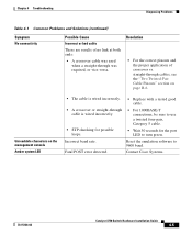
... Twisted-Pair Cable Pinouts" section on the management console Amber system LED • The cable is wired incorrectly. • A crossover or straight-through was required, or vice-versa. Contact Cisco Systems. 78-15136-02 Catalyst 3750 Switch Hardware Installation Guide 4-5 Chapter 4 Troubleshooting Diagnosing Problems Table 4-1 Common Problems and Solutions (continued) Symptom No connectivity Possible Cause Incorrect or bad cable These are results of crossover vs. Reset the emulation software to turn green.
... Twisted-Pair Cable Pinouts" section on the management console Amber system LED • The cable is wired incorrectly. • A crossover or straight-through was required, or vice-versa. Contact Cisco Systems. 78-15136-02 Catalyst 3750 Switch Hardware Installation Guide 4-5 Chapter 4 Troubleshooting Diagnosing Problems Table 4-1 Common Problems and Solutions (continued) Symptom No connectivity Possible Cause Incorrect or bad cable These are results of crossover vs. Reset the emulation software to turn green.
Hardware Installation Guide
Page 143
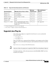
... the instructions in the README_FIRST.txt file to access and run the Java-based CMS: • Java plug-in 1.4 • Java plug-in 1.3.1 These Java plug-ins are supported both in . 78-15136-02 Catalyst 3750 Switch Hardware Installation Guide C-7 Appendix C Managing the Switch by Using the Cluster Management Suite CMS Requirements Table C-2 Supported Operating Systems and Browsers Operating System Netscape Microsoft Internet Minimum Service Pack...
... the instructions in the README_FIRST.txt file to access and run the Java-based CMS: • Java plug-in 1.4 • Java plug-in 1.3.1 These Java plug-ins are supported both in . 78-15136-02 Catalyst 3750 Switch Hardware Installation Guide C-7 Appendix C Managing the Switch by Using the Cluster Management Suite CMS Requirements Table C-2 Supported Operating Systems and Browsers Operating System Netscape Microsoft Internet Minimum Service Pack...
Hardware Installation Guide
Page 156
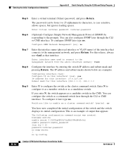
... D Quick Setup By Using the CLI-Based Setup Program D-12 Step 5 Enter a virtual terminal (Telnet) password, and press Return. For this interface [255.0.0.0]: 255.0.0.0 Step 9 Enter Y to configure the switch as that connects to configure it later type no You have now completed the initial configuration of the interface that interface. no . To configure SNMP later type no ip routing Catalyst 3750 Switch Hardware Installation Guide 78-15136-02 Configuring interface vlan1: Configure IP on this interface? [yes]: yes IP address for...
... D Quick Setup By Using the CLI-Based Setup Program D-12 Step 5 Enter a virtual terminal (Telnet) password, and press Return. For this interface [255.0.0.0]: 255.0.0.0 Step 9 Enter Y to configure the switch as that connects to configure it later type no You have now completed the initial configuration of the interface that interface. no . To configure SNMP later type no ip routing Catalyst 3750 Switch Hardware Installation Guide 78-15136-02 Configuring interface vlan1: Configure IP on this interface? [yes]: yes IP address for...
Hardware Installation Guide
Page 157
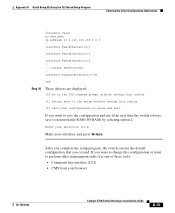
... Switch Hardware Installation Guide D-13 If you want to nvram and exit. interface FastEthernet1/0/2 interface FastEthernet1/0/3 ! ... ! interface FastEthernet1/0/1 ! After you complete the setup program, the switch can run the default configuration that you want to change this configuration to save the configuration and use one of these tools: • Command-line interface (CLI) • CMS from your selection, and press Return. interface Vlan1 no shutdown ip address 10.4.120.106 255.0.0.0 ! Appendix D Quick Setup...
... Switch Hardware Installation Guide D-13 If you want to nvram and exit. interface FastEthernet1/0/2 interface FastEthernet1/0/3 ! ... ! interface FastEthernet1/0/1 ! After you complete the setup program, the switch can run the default configuration that you want to change this configuration to save the configuration and use one of these tools: • Command-line interface (CLI) • CMS from your selection, and press Return. interface Vlan1 no shutdown ip address 10.4.120.106 255.0.0.0 ! Appendix D Quick Setup...


