
Hardware Installation Guide
Page 9
... Terminal to the Console Port 3-8 Powering On the Switch and Running POST 3-10 Powering Off the Switch and Disconnecting the Console Port 3-11 Planning the Stack 3-12 Planning Considerations 3-12 Powering Considerations 3-13 Cabling Considerations 3-14 Recommended Cabling Configurations 3-15 Installing the Switch 3-17 Rack Mounting 3-18 Removing Screws from the...
... Terminal to the Console Port 3-8 Powering On the Switch and Running POST 3-10 Powering Off the Switch and Disconnecting the Console Port 3-11 Planning the Stack 3-12 Planning Considerations 3-12 Powering Considerations 3-13 Cabling Considerations 3-14 Recommended Cabling Configurations 3-15 Installing the Switch 3-17 Rack Mounting 3-18 Removing Screws from the...

Hardware Installation Guide
Page 10
... to 1000BASE-T SFP Modules 3-48 Where to Go Next 3-50 4 C H A P T E R Troubleshooting 4-1 Understanding POST Results 4-1 Clearing the Switch IP Address and Configuration 4-2 Diagnosing Problems 4-3 Replacing a Failed Stack Member 4-7 A A P P E N D I X Technical Specifications A-1 B A P P E N D I X Connector and Cable Specifications B-1 Connector Specifications B-1 10/100/1000 Ports B-1 Connecting to 1000BASE-T Devices B-2 10/100 Ports B-3 SFP Module Ports B-5 Console Port...
... to 1000BASE-T SFP Modules 3-48 Where to Go Next 3-50 4 C H A P T E R Troubleshooting 4-1 Understanding POST Results 4-1 Clearing the Switch IP Address and Configuration 4-2 Diagnosing Problems 4-3 Replacing a Failed Stack Member 4-7 A A P P E N D I X Technical Specifications A-1 B A P P E N D I X Connector and Cable Specifications B-1 Connector Specifications B-1 10/100/1000 Ports B-1 Connecting to 1000BASE-T Devices B-2 10/100 Ports B-3 SFP Module Ports B-5 Console Port...

Hardware Installation Guide
Page 11
... for Accessing the CLI D-2 Accessing the CLI Through Express Setup (Unconfigured Switch Only) D-2 Accessing the CLI Through the Console Port D-3 Taking Out What You Need D-4 Stacking the Switches (Optional) D-5 Connecting to the Console Port D-7 Starting the Terminal Emulation Software D-9 Connecting to a Power Source D-9 Entering the Initial Configuration Information D-10 IP Settings...
... for Accessing the CLI D-2 Accessing the CLI Through Express Setup (Unconfigured Switch Only) D-2 Accessing the CLI Through the Console Port D-3 Taking Out What You Need D-4 Stacking the Switches (Optional) D-5 Connecting to the Console Port D-7 Starting the Terminal Emulation Software D-9 Connecting to a Power Source D-9 Entering the Initial Configuration Information D-10 IP Settings...

Hardware Installation Guide
Page 12
Contents E A P P E N D I X INDEX Translated Safety Warnings E-1 Attaching the Cisco RPS (model PWR300-AC-RPS-N1) E-1 Attaching the Cisco RPS (model PWR675-AC-RPS-N1) E-2 Installation Warning E-4 Installation Instructions E-5 Jewelry Removal Warning E-6 Stacking the Chassis Warning E-8 Main Disconnecting Device E-10 Grounded Equipment Warning E-11 Installing or Replacing the Unit E-12 Overtemperature Warning E-14 Working During Lightning...
Contents E A P P E N D I X INDEX Translated Safety Warnings E-1 Attaching the Cisco RPS (model PWR300-AC-RPS-N1) E-1 Attaching the Cisco RPS (model PWR675-AC-RPS-N1) E-2 Installation Warning E-4 Installation Instructions E-5 Jewelry Removal Warning E-6 Stacking the Chassis Warning E-8 Main Disconnecting Device E-10 Grounded Equipment Warning E-11 Installing or Replacing the Unit E-12 Overtemperature Warning E-14 Working During Lightning...
Hardware Installation Guide
Page 29
... of the switch to determine the release. For quick setup instructions for a standalone switch or a switch stack. If you are installing a new switch, refer to the Cisco IOS release label on switches running releases earlier than Cisco IOS Release 12.1(14)EA1, go to Go Next, page 1-12 78-15136-02 Catalyst 3750... D, "Quick Setup By Using the CLI-Based Setup Program." CH A P T E R 1 Using Express Setup This chapter provides a quick, step-by-step setup procedure for switches running Cisco IOS Release 12.1(14)EA1 or later.
... of the switch to determine the release. For quick setup instructions for a standalone switch or a switch stack. If you are installing a new switch, refer to the Cisco IOS release label on switches running releases earlier than Cisco IOS Release 12.1(14)EA1, go to Go Next, page 1-12 78-15136-02 Catalyst 3750... D, "Quick Setup By Using the CLI-Based Setup Program." CH A P T E R 1 Using Express Setup This chapter provides a quick, step-by-step setup procedure for switches running Cisco IOS Release 12.1(14)EA1 or later.
Hardware Installation Guide
Page 30
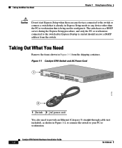
... Need Remove the items shown in Figure 1-1 from the switch. Figure 1-1 Catalyst 3750 Switch and AC Power Cord 1 SYST RPS MASTR STAT 1X DUPLX SPEED STACK MODE 2X 11X 13X 12X 14X 23X Catalyst 3750 SERIES 24X 97175 2 1 Switch 2 AC power cord You also need to provide an Ethernet (Category 5) straight...
... Need Remove the items shown in Figure 1-1 from the switch. Figure 1-1 Catalyst 3750 Switch and AC Power Cord 1 SYST RPS MASTR STAT 1X DUPLX SPEED STACK MODE 2X 11X 13X 12X 14X 23X Catalyst 3750 SERIES 24X 97175 2 1 Switch 2 AC power cord You also need to provide an Ethernet (Category 5) straight...

Hardware Installation Guide
Page 31
Figure 1-3 Connecting the Power 1 STACK 1 STACK 2 CONSOLE 1.2A-100R>06A-A2T4,IN05GV0-~60 HZ DSCPIENPCPO+IUWF1T2IEESvDRFISO@NUR1MP3RPAAELNYMUOATLE 97176 1 Switch 2 2 AC power cord 78-15136-02 Catalyst 3750 Switch Hardware Installation Guide 1-3 Chapter 1 Using Express Setup Figure 1-2 Ethernet Cable Powering On the Switch 89887 Powering On the Switch Complete these steps to power on the switch: Step 1 Connect one end of the AC power cord to the power connector on the switch rear panel, as shown in Figure 1-3.
Figure 1-3 Connecting the Power 1 STACK 1 STACK 2 CONSOLE 1.2A-100R>06A-A2T4,IN05GV0-~60 HZ DSCPIENPCPO+IUWF1T2IEESvDRFISO@NUR1MP3RPAAELNYMUOATLE 97176 1 Switch 2 2 AC power cord 78-15136-02 Catalyst 3750 Switch Hardware Installation Guide 1-3 Chapter 1 Using Express Setup Figure 1-2 Ethernet Cable Powering On the Switch 89887 Powering On the Switch Complete these steps to power on the switch: Step 1 Connect one end of the AC power cord to the power connector on the switch rear panel, as shown in Figure 1-3.

Hardware Installation Guide
Page 32
... SYST and STAT LEDs are any devices connected to local routers and the Internet. If the POST fails, see the "Understanding POST Results" section on a stack master switch. Starting Express Setup Express Setup is also required if you can connect to the switch. For information about troubleshooting a POST failure, see Chapter...
... SYST and STAT LEDs are any devices connected to local routers and the Internet. If the POST fails, see the "Understanding POST Results" section on a stack master switch. Starting Express Setup Express Setup is also required if you can connect to the switch. For information about troubleshooting a POST failure, see Chapter...

Hardware Installation Guide
Page 33
... on the front panel of the LEDs begin to the switch. This takes approximately 3 seconds. Figure 1-4 Starting Express Setup SYST RPS MASTR STAT DUPLX SPEED STACK MODE 97173 1 1 Mode button Step 3 Release the Mode button. Press and hold the Mode button, as shown in Figure 1-4, until the four LEDs above the...
... on the front panel of the LEDs begin to the switch. This takes approximately 3 seconds. Figure 1-4 Starting Express Setup SYST RPS MASTR STAT DUPLX SPEED STACK MODE 97173 1 1 Mode button Step 3 Release the Mode button. Press and hold the Mode button, as shown in Figure 1-4, until the four LEDs above the...

Hardware Installation Guide
Page 34
... 10.0.0.1, as shown in Figure 1-6, and press Enter. Figure 1-5 Connecting the Switch and PC or Workstation Ethernet Ports 1 SYST RPS MASTR STAT 1X DUPLX SPEED STACK MODE 2X 11X 13X 12X 14X 23X Catalyst 3750 SERIES 24X 2 97174 3 1 Switch 2 Ethernet cable 3 PC or workstation Step 5 Step 6 Step 7 Connect the other than...
... 10.0.0.1, as shown in Figure 1-6, and press Enter. Figure 1-5 Connecting the Switch and PC or Workstation Ethernet Ports 1 SYST RPS MASTR STAT 1X DUPLX SPEED STACK MODE 2X 11X 13X 12X 14X 23X Catalyst 3750 SERIES 24X 2 97174 3 1 Switch 2 Ethernet cable 3 PC or workstation Step 5 Step 6 Step 7 Connect the other than...

Hardware Installation Guide
Page 42
... speed and duplex settings - For 10/100/1000 ports, autonegotiates the speed and supports only full-duplex mode • The Catalyst 3750 switches support stacking. Catalyst 3750G-12S-12 SFP module slots • The switches support these SFP modules: - 1000BASE-SX - 1000BASE-LX - 1000BASE-T Note When.... Catalyst 3750G-24T-24 10/100/1000 Ethernet ports - Catalyst 3750 Switch Hardware Installation Guide 2-2 78-15136-02 Connection for optional Cisco RPS 300 redundant power system that operates on AC input and supplies backup DC power output to nine switches in half-duplex mode at...
... speed and duplex settings - For 10/100/1000 ports, autonegotiates the speed and supports only full-duplex mode • The Catalyst 3750 switches support stacking. Catalyst 3750G-12S-12 SFP module slots • The switches support these SFP modules: - 1000BASE-SX - 1000BASE-LX - 1000BASE-T Note When.... Catalyst 3750G-24T-24 10/100/1000 Ethernet ports - Catalyst 3750 Switch Hardware Installation Guide 2-2 78-15136-02 Connection for optional Cisco RPS 300 redundant power system that operates on AC input and supplies backup DC power output to nine switches in half-duplex mode at...

Hardware Installation Guide
Page 43
... family of the pair (port 1) is above the second member (port 2) on . Figure 2-1 Catalyst 3750-24TS Front Panel 86541 SYST RPS MASTR STAT DUPLX SPEED STACK MODE 12 1X 34 56 78 9 10 11 12 11X 2X 12X 13 14 13X 15 16 17 18 19 20 21 22 23 24.../100 ports 2 SFP module ports The 10/100/1000 ports on the left, as shown in pairs. Chapter 2 Product Overview Front Panel Description Note The Cisco RPS 300 does not support the Catalyst 3750G-24TS switch. - The first member of Catalyst 3750 switches. In Figure 2-3 the SFP port are grouped in...
... family of the pair (port 1) is above the second member (port 2) on . Figure 2-1 Catalyst 3750-24TS Front Panel 86541 SYST RPS MASTR STAT DUPLX SPEED STACK MODE 12 1X 34 56 78 9 10 11 12 11X 2X 12X 13 14 13X 15 16 17 18 19 20 21 22 23 24.../100 ports 2 SFP module ports The 10/100/1000 ports on the left, as shown in pairs. Chapter 2 Product Overview Front Panel Description Note The Cisco RPS 300 does not support the Catalyst 3750G-24TS switch. - The first member of Catalyst 3750 switches. In Figure 2-3 the SFP port are grouped in...

Hardware Installation Guide
Page 44
The ports are numbered 1 through 12. Front Panel Description Figure 2-2 Catalyst 3750G-24T Front Panel SYST RPS MASTR STAT DUPLX SPEED STACK MODE 12 1X 34 56 78 9 10 11 12 11X 2X 12X 13 14 13X 15 16 17 18 19 20 21 22 23 24 ... 24X 1 Catalyst 3750 SERIES 1 10/100/1000 ports Figure 2-3 Catalyst 3750G-24TS Front Panel Chapter 2 Product Overview 86543 86544 SYST RPS MASTR STAT DUPLX SPEED STACK MODE 12 1X 34 56 78 9 10 11 12 11X 2X 12X 13 14 13X 15 16 17 18 19 20 21 22 23 24...
The ports are numbered 1 through 12. Front Panel Description Figure 2-2 Catalyst 3750G-24T Front Panel SYST RPS MASTR STAT DUPLX SPEED STACK MODE 12 1X 34 56 78 9 10 11 12 11X 2X 12X 13 14 13X 15 16 17 18 19 20 21 22 23 24 ... 24X 1 Catalyst 3750 SERIES 1 10/100/1000 ports Figure 2-3 Catalyst 3750G-24TS Front Panel Chapter 2 Product Overview 86543 86544 SYST RPS MASTR STAT DUPLX SPEED STACK MODE 12 1X 34 56 78 9 10 11 12 11X 2X 12X 13 14 13X 15 16 17 18 19 20 21 22 23 24...

Hardware Installation Guide
Page 45
... above port 4, and so on . The ports are numbered 1 through 48. Figure 2-5 Catalyst 3750-48TS Front Panel 86542 SYST RPS MASTR STAT DUPLX SPEED STACK MODE 12 1X 2X 34 56 78 9 10 11 12 13 14 15 16 17 18 15X 17X 16X 18X 19 20 21 22 23... Catalyst 3750 Switch Hardware Installation Guide 2-5 Chapter 2 Product Overview Figure 2-4 Catalyst 3750G-12S Front Panel Front Panel Description 97166 SYST RPS MASTR STAT DUPLX SPEED STACK MODE 1 2 3 4 5 6 7 8 9 10 Catalyst 3750 SERIES 11 12 1 1 SFP module ports The Catalyst 3750-48TS 10/100 ports are grouped in Figure 2-1. The first ...
... above port 4, and so on . The ports are numbered 1 through 48. Figure 2-5 Catalyst 3750-48TS Front Panel 86542 SYST RPS MASTR STAT DUPLX SPEED STACK MODE 12 1X 2X 34 56 78 9 10 11 12 13 14 15 16 17 18 15X 17X 16X 18X 19 20 21 22 23... Catalyst 3750 Switch Hardware Installation Guide 2-5 Chapter 2 Product Overview Figure 2-4 Catalyst 3750G-12S Front Panel Front Panel Description 97166 SYST RPS MASTR STAT DUPLX SPEED STACK MODE 1 2 3 4 5 6 7 8 9 10 Catalyst 3750 SERIES 11 12 1 1 SFP module ports The Catalyst 3750-48TS 10/100 ports are grouped in Figure 2-1. The first ...

Hardware Installation Guide
Page 48
... and switch clusters. All of the port modes. Figure 2-6 Catalyst 3750 LEDs SYST RPS MASTR STAT DUPLX SPEED STACK MODE 12345678 9 12 1X 34 56 78 9 10 11 12 11X 2X 12X 1 Mode button 2 Stack LED 3 Speed LED 4 Duplex LED 5 Status LED 6 Master LED 7 RPS LED 8 System LED 9 Port LED 86545 Catalyst...
... and switch clusters. All of the port modes. Figure 2-6 Catalyst 3750 LEDs SYST RPS MASTR STAT DUPLX SPEED STACK MODE 12345678 9 12 1X 34 56 78 9 10 11 12 11X 2X 12X 1 Mode button 2 Stack LED 3 Speed LED 4 Duplex LED 5 Status LED 6 Master LED 7 RPS LED 8 System LED 9 Port LED 86545 Catalyst...

Hardware Installation Guide
Page 50
... 3750 Switch Hardware Installation Guide 78-15136-02 When you press the Mode button on the stack master to interpret the port LED colors in the stack change to the Cisco RPS 300 Redundant Power System Hardware Installation Guide. These port LEDs, as a group or individually..., display information about the switch and about the Cisco RPS 300, refer to display the same selected mode. An error occurred when the switch was selecting the stack master switch or a stack error. Table 2-3 Master LED Port Mode Off Green Amber Description Switch ...
... 3750 Switch Hardware Installation Guide 78-15136-02 When you press the Mode button on the stack master to interpret the port LED colors in the stack change to the Cisco RPS 300 Redundant Power System Hardware Installation Guide. These port LEDs, as a group or individually..., display information about the switch and about the Cisco RPS 300, refer to display the same selected mode. An error occurred when the switch was selecting the stack master switch or a stack error. Table 2-3 Master LED Port Mode Off Green Amber Description Switch ...
Hardware Installation Guide
Page 51
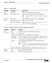
... ports operate only in full duplex. 78-15136-02 Catalyst 3750 Switch Hardware Installation Guide 2-11 The StackWise port status. See the "Stack LED" section on the Switch Port Mode STAT (port status) DUPLX (duplex) LED Color Meaning Off No link, or port was administratively...Chapter 2 Product Overview Front Panel Description Table 2-4 Port Mode LEDs Mode LED STAT DUPLX Port Mode Port status Port duplex mode SPEED STACK Port speed Stack Member Status StackWise Port Status Description The port status. This is transmitting or receiving data. Table 2-5 Meaning of LED Colors in ...
... ports operate only in full duplex. 78-15136-02 Catalyst 3750 Switch Hardware Installation Guide 2-11 The StackWise port status. See the "Stack LED" section on the Switch Port Mode STAT (port status) DUPLX (duplex) LED Color Meaning Off No link, or port was administratively...Chapter 2 Product Overview Front Panel Description Table 2-4 Port Mode LEDs Mode LED STAT DUPLX Port Mode Port status Port duplex mode SPEED STACK Port speed Stack Member Status StackWise Port Status Description The port status. This is transmitting or receiving data. Table 2-5 Meaning of LED Colors in ...

Hardware Installation Guide
Page 52
... are amber when the ports are solid green, as these represent the member numbers of other switches in a stack. When the stack LED is operating at 100 Mbps. STACK Off No stack member corresponding to nine switches can operate at 10, 100, or 1000 Mbps in full-duplex mode or in ..., the port LED 8 flashes green because this represents the member number of other port LEDs are off because there are no more members in a stack. The first nine port LEDs show the status for StackWise ports 1 and 2, respectively. 2-12 Catalyst 3750 Switch Hardware Installation Guide 78-15136-02 ...
... are amber when the ports are solid green, as these represent the member numbers of other switches in a stack. When the stack LED is operating at 100 Mbps. STACK Off No stack member corresponding to nine switches can operate at 10, 100, or 1000 Mbps in full-duplex mode or in ..., the port LED 8 flashes green because this represents the member number of other port LEDs are off because there are no more members in a stack. The first nine port LEDs show the status for StackWise ports 1 and 2, respectively. 2-12 Catalyst 3750 Switch Hardware Installation Guide 78-15136-02 ...

Hardware Installation Guide
Page 53
...and 12 on all the switches in the stack, the stack is not operating at full bandwidth (32 Gbps). Figure 2-7 Stack LED SYST RPS MASTR STAT DUPLX SPEED STACK MODE SYST RPS MASTR STAT DUPLX SPEED STACK MODE SYST RPS MASTR STAT DUPLX SPEED STACK MODE 12 1X 2X 12 1X 2X 12...3750 SERIES 1 2 3 48X 4 7 47 48 8 9 Catalyst 3750 SERIES 47X 1 2 3 48X 4 47 48 47X Catalyst 3750 SERIES 1 2 10 3 48X 4 11 12 13 1 2 3 86686 1 Stack member 8 2 Stack member 3 3 Stack member 4 78-15136-02 Catalyst 3750 Switch Hardware Installation Guide 2-13 Note If both the port LEDs are not green, the...
...and 12 on all the switches in the stack, the stack is not operating at full bandwidth (32 Gbps). Figure 2-7 Stack LED SYST RPS MASTR STAT DUPLX SPEED STACK MODE SYST RPS MASTR STAT DUPLX SPEED STACK MODE SYST RPS MASTR STAT DUPLX SPEED STACK MODE 12 1X 2X 12 1X 2X 12...3750 SERIES 1 2 3 48X 4 7 47 48 8 9 Catalyst 3750 SERIES 47X 1 2 3 48X 4 47 48 47X Catalyst 3750 SERIES 1 2 10 3 48X 4 11 12 13 1 2 3 86686 1 Stack member 8 2 Stack member 3 3 Stack member 4 78-15136-02 Catalyst 3750 Switch Hardware Installation Guide 2-13 Note If both the port LEDs are not green, the...

Hardware Installation Guide
Page 54
...-45 console port, and two StackWise ports. (See Figure 2-8 and Figure 2-9.) Figure 2-8 Catalyst 3750-24TS, 3750G-24T, 3750G-12S, and 3750-48TS Rear Panel 86548 STACK 1 STACK 2 CONSOLE 1.6A-100R>09A-A2T0,IN05GV0-~60 HZ [email protected] 1 23 4 5 1 StackWise ports 2 RJ-45 console port 3 Fan exhaust 4 AC power connector 5 RPS...
...-45 console port, and two StackWise ports. (See Figure 2-8 and Figure 2-9.) Figure 2-8 Catalyst 3750-24TS, 3750G-24T, 3750G-12S, and 3750-48TS Rear Panel 86548 STACK 1 STACK 2 CONSOLE 1.6A-100R>09A-A2T0,IN05GV0-~60 HZ [email protected] 1 23 4 5 1 StackWise ports 2 RJ-45 console port 3 Fan exhaust 4 AC power connector 5 RPS...