
Installation Guide
Page 29
...-Panel Description Table 1-2 Catalyst 3512, 3524, 3524-PWR, and 3548 XL Features (continued) Feature Description (continued) Management • Cisco IOS CLI through the console port or Telnet • CiscoView device-management application • Cluster Management Suite, a web-based tool for managing switch clusters or an individual switch through a single IP address • SNMP Power Redundancy • Connection for optional Cisco RPS 600 that operates on AC input and supplies DC...
...-Panel Description Table 1-2 Catalyst 3512, 3524, 3524-PWR, and 3548 XL Features (continued) Feature Description (continued) Management • Cisco IOS CLI through the console port or Telnet • CiscoView device-management application • Cluster Management Suite, a web-based tool for managing switch clusters or an individual switch through a single IP address • SNMP Power Redundancy • Connection for optional Cisco RPS 600 that operates on AC input and supplies DC...

Installation Guide
Page 33
... power source, and the second power source is its backup. The power source to an AC power source for redundant power. Using the required Cisco proprietary signaling and cabling, the maximum distance for a GigaStack GBIC-to other Gigabit Ethernet devices. The Auto setting is the default. The GigaStack GBIC supports one full-duplex link (in a point-to-point configuration) or up to nine half-duplex links (in a stack configuration) to -GigaStack GBIC connection...
... power source, and the second power source is its backup. The power source to an AC power source for redundant power. Using the required Cisco proprietary signaling and cabling, the maximum distance for a GigaStack GBIC-to other Gigabit Ethernet devices. The Auto setting is the default. The GigaStack GBIC supports one full-duplex link (in a point-to-point configuration) or up to nine half-duplex links (in a stack configuration) to -GigaStack GBIC connection...
Installation Guide
Page 49
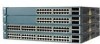
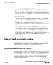
...; Simple Network Management Protocol (SNMP) network management You can manage switches from an SNMP-compatible management station that came with your network users and the relative priority of the network applications they use to set of an SNMP network-management platform. Chapter 1 Product Overview Network Configuration Examples • Cisco IOS command-line interface (CLI) Connect a PC or terminal directly to the console port, located on the rear panel of using the switch to create dedicated network segments and interconnecting the segments through Fast Ethernet and Gigabit Ethernet...
...; Simple Network Management Protocol (SNMP) network management You can manage switches from an SNMP-compatible management station that came with your network users and the relative priority of the network applications they use to set of an SNMP network-management platform. Chapter 1 Product Overview Network Configuration Examples • Cisco IOS command-line interface (CLI) Connect a PC or terminal directly to the console port, located on the rear panel of using the switch to create dedicated network segments and interconnecting the segments through Fast Ethernet and Gigabit Ethernet...
Installation Guide
Page 83
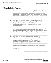
... the command-line interface (CLI) to customize your system administrator: Switch IP address Subnet mask (netmask 78-6456-04 Catalyst 3500 Series XL Hardware Installation Guide 2-25 Later, you can use the Cluster Management Suite to assign IP information or a password. To run the setup program, access the switch from the PC terminal that prompts you need the following information from your configuration. If you connected to the console port. (See the "Connecting...
... the command-line interface (CLI) to customize your system administrator: Switch IP address Subnet mask (netmask 78-6456-04 Catalyst 3500 Series XL Hardware Installation Guide 2-25 Later, you can use the Cluster Management Suite to assign IP information or a password. To run the setup program, access the switch from the PC terminal that prompts you need the following information from your configuration. If you connected to the console port. (See the "Connecting...

Installation Guide
Page 96
... is amber on the switch has failed. Possible Cause • Internal fan fault detected. • Switch is connected to the LAN-to check if a fan on the Catalyst 3524-PWR XL. Make sure the switch is overheating. • Nonfatal or fatal POST error detected. Catalyst 3500 Series XL Hardware Installation Guide 3-6 78-6456-04 when connected to power on the Cisco IP Phone. Resolution • Either check the switch itself or use...
... is amber on the switch has failed. Possible Cause • Internal fan fault detected. • Switch is connected to the LAN-to check if a fan on the Catalyst 3524-PWR XL. Make sure the switch is overheating. • Nonfatal or fatal POST error detected. Catalyst 3500 Series XL Hardware Installation Guide 3-6 78-6456-04 when connected to power on the Cisco IP Phone. Resolution • Either check the switch itself or use...

Hardware Installation Guide
Page 18
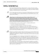
.... You cannot configure half-duplex mode on Gigabit Ethernet interfaces if the interface speed is 1000 Mb/s. • When set to 52. Statement 1072 • 100BASE-TX and 1000BASE-T traffic requires Category 5 cable. 10BASE-T traffic can be within the restricted access location are made using such interconnection methods, unless the exposed metal parts are located within a restricted access location and users and service people who are numbered 49 to...
.... You cannot configure half-duplex mode on Gigabit Ethernet interfaces if the interface speed is 1000 Mb/s. • When set to 52. Statement 1072 • 100BASE-TX and 1000BASE-T traffic requires Category 5 cable. 10BASE-T traffic can be within the restricted access location are made using such interconnection methods, unless the exposed metal parts are located within a restricted access location and users and service people who are numbered 49 to...

Hardware Installation Guide
Page 19
... on the switch provide PoE support for connections to enable the automatic medium-dependent interface crossover (auto-MDIX) feature. For information about configuring and monitoring PoE ports, see the switch software configuration guide. For configuration information for this feature, see the documentation that came with IEEE 802.3af and Cisco prestandard PoE support for copper Ethernet connections and configures the interfaces accordingly. The device manager, Network Assistant, and the CLI provide PoE settings for proper operation. On the Catalyst 3560...
... on the switch provide PoE support for connections to enable the automatic medium-dependent interface crossover (auto-MDIX) feature. For information about configuring and monitoring PoE ports, see the switch software configuration guide. For configuration information for this feature, see the documentation that came with IEEE 802.3af and Cisco prestandard PoE support for copper Ethernet connections and configures the interfaces accordingly. The device manager, Network Assistant, and the CLI provide PoE settings for proper operation. On the Catalyst 3560...

Hardware Installation Guide
Page 36
... connection must comply with standard practices for Installation Chapter 2 Switch Installation (24- Statement 1046 Warning This warning symbol means danger. Use the statement number provided at the end of each warning to install, replace, or service this product should be grounded. Statement 1072 Warning No user-serviceable parts inside. Contact the appropriate electrical inspection authority or an electrician if you work on Power over Ethernet (PoE...
... connection must comply with standard practices for Installation Chapter 2 Switch Installation (24- Statement 1046 Warning This warning symbol means danger. Use the statement number provided at the end of each warning to install, replace, or service this product should be grounded. Statement 1072 Warning No user-serviceable parts inside. Contact the appropriate electrical inspection authority or an electrician if you work on Power over Ethernet (PoE...

Hardware Installation Guide
Page 37
..., PoE or non-PoE 10/100/1000 Ethernet port cables that might be up to ports is DC-isolated (DC-I). If the switch is within the ranges listed in Table B-1 on page B-4, which lists the cable specifications for 1000BASE-X and 100BASE-X SFP modules for electromagnetic compatibility and safety, connect the ethernet cables only to avoid overloading the receiver. Chapter 2 Switch Installation (24- The rear-panel power connector is installed in the link...
..., PoE or non-PoE 10/100/1000 Ethernet port cables that might be up to ports is DC-isolated (DC-I). If the switch is within the ranges listed in Table B-1 on page B-4, which lists the cable specifications for 1000BASE-X and 100BASE-X SFP modules for electromagnetic compatibility and safety, connect the ethernet cables only to avoid overloading the receiver. Chapter 2 Switch Installation (24- The rear-panel power connector is installed in the link...

Hardware Installation Guide
Page 38
... a system malfunction. See the "Cisco RPS" section on Cisco.com describes the box contents. Statement 370 Catalyst 3560 Switch Hardware Installation Guide 2-6 OL-6337-07 Network Equipment Building Systems (NEBS) GR-63-CORE - To power on a table or shelf, you connect the RPS to run Express Setup. Verifying Switch Operation Before you install the switch in standby mode. Set the RPS to all Cisco Ethernet switches except for the steps required...
... a system malfunction. See the "Cisco RPS" section on Cisco.com describes the box contents. Statement 370 Catalyst 3560 Switch Hardware Installation Guide 2-6 OL-6337-07 Network Equipment Building Systems (NEBS) GR-63-CORE - To power on a table or shelf, you connect the RPS to run Express Setup. Verifying Switch Operation Before you install the switch in standby mode. Set the RPS to all Cisco Ethernet switches except for the steps required...
Hardware Installation Guide
Page 47
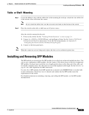
... the list of supported SFP modules. You can use the CLI setup program, see the SFP module documentation. Use only Cisco SFP modules. Mounting Step 1 Locate the adhesive strip with security information, which Cisco uses to the bottom of the switch. After the switch is encoded with the rubber feet in the rack: 1. To use any combination of the cable, and for the switch. OL-6337-07 Catalyst 3560 Switch Hardware Installation Guide 2-15 See the "Verifying Switch Operation...
... the list of supported SFP modules. You can use the CLI setup program, see the SFP module documentation. Use only Cisco SFP modules. Mounting Step 1 Locate the adhesive strip with security information, which Cisco uses to the bottom of the switch. After the switch is encoded with the rubber feet in the rack: 1. To use any combination of the cable, and for the switch. OL-6337-07 Catalyst 3560 Switch Hardware Installation Guide 2-15 See the "Verifying Switch Operation...
Hardware Installation Guide
Page 51
... accessed only through cable for configuring the Ethernet ports: • Let the ports autonegotiate both ends of the connection. For releases between Cisco IOS Release 12.1(14)EA1 and 12.2(18)SE, the auto-MDIX feature is enabled, the switch detects the required cable type for this feature, see the switch software configuration guide or the switch command reference. Connecting devices that causes a PoE fault from the network. Chapter 2 Switch Installation (24- The default setting is set can use...
... accessed only through cable for configuring the Ethernet ports: • Let the ports autonegotiate both ends of the connection. For releases between Cisco IOS Release 12.1(14)EA1 and 12.2(18)SE, the auto-MDIX feature is enabled, the switch detects the required cable type for this feature, see the switch software configuration guide or the switch command reference. Connecting devices that causes a PoE fault from the network. Chapter 2 Switch Installation (24- The default setting is set can use...
Hardware Installation Guide
Page 54
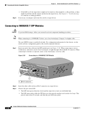
... Figure 2-20). See Chapter 4, "Troubleshooting," for loops. When connecting to cabling problems. If necessary, reconfigure and restart the switch or target device. Step 1 Insert one end of the cable into the SFP module port (see the switch software configuration guide or the switch command reference. This process takes about 30 seconds, and then the port LED turns green. 2-22 Catalyst 3560 Switch Hardware Installation Guide OL-6337-07 Connecting the Switch to a 1000BASE-T SFP Module 97932 40 41 42...
... Figure 2-20). See Chapter 4, "Troubleshooting," for loops. When connecting to cabling problems. If necessary, reconfigure and restart the switch or target device. Step 1 Insert one end of the cable into the SFP module port (see the switch software configuration guide or the switch command reference. This process takes about 30 seconds, and then the port LED turns green. 2-22 Catalyst 3560 Switch Hardware Installation Guide OL-6337-07 Connecting the Switch to a 1000BASE-T SFP Module 97932 40 41 42...
Hardware Installation Guide
Page 60
... 1030 Warning Ultimate disposal of security. Statement 1024 Warning This unit might have more than one power supply connection. A restricted access area can be aware of a suitably installed ground conductor. Statement 1072 Warning No user-serviceable parts inside. Avoid using uninsulated exposed metal contacts, conductors, or terminals. and 12-Port Switches) Warning This equipment must be familiar with local and national electrical...
... 1030 Warning Ultimate disposal of security. Statement 1024 Warning This unit might have more than one power supply connection. A restricted access area can be aware of a suitably installed ground conductor. Statement 1072 Warning No user-serviceable parts inside. Avoid using uninsulated exposed metal contacts, conductors, or terminals. and 12-Port Switches) Warning This equipment must be familiar with local and national electrical...
Hardware Installation Guide
Page 62
... link. • Cisco Ethernet Switches are available from the switch to connected devices can order an optional cable guard to secure cables to the front of suspended particulate matter: - and 12-Port Switches) • Cabling is safely away from Cisco. However, these fans and blowers can order a kit (part number ACS-DSBUASYN=) with cooling mechanisms, such as radios, power lines, and fluorescent lighting fixtures. You must install this compact model...
... link. • Cisco Ethernet Switches are available from the switch to connected devices can order an optional cable guard to secure cables to the front of suspended particulate matter: - and 12-Port Switches) • Cabling is safely away from Cisco. However, these fans and blowers can order a kit (part number ACS-DSBUASYN=) with cooling mechanisms, such as radios, power lines, and fluorescent lighting fixtures. You must install this compact model...
Hardware Installation Guide
Page 72
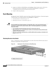
... of the switch. Rack-Mounting Installing the Catalyst 3560-8PC switch or the Catalyst 3560 12-PC-S switch in a 19-inch rack requires a bracket kit that is provided with the CLI-Based Setup Program." 4. See the Catalyst 3560 Switch Getting Started Guide for Rack-Mounting SYST STAT DPLX SPD PoE MODE CONSOLE 1x 2x 3x 4x 5x 6x 7x 8x Catalyst 3560 SERIES PoE-8 1 1 1 Phillips flat-head screws 3-16 Catalyst 3560 Switch Hardware Installation Guide OL-6337...
... of the switch. Rack-Mounting Installing the Catalyst 3560-8PC switch or the Catalyst 3560 12-PC-S switch in a 19-inch rack requires a bracket kit that is provided with the CLI-Based Setup Program." 4. See the Catalyst 3560 Switch Getting Started Guide for Rack-Mounting SYST STAT DPLX SPD PoE MODE CONSOLE 1x 2x 3x 4x 5x 6x 7x 8x Catalyst 3560 SERIES PoE-8 1 1 1 Phillips flat-head screws 3-16 Catalyst 3560 Switch Hardware Installation Guide OL-6337...
Hardware Installation Guide
Page 77
... power-on Cisco.com or the documentation that came with your SNMP application for more information. • Evaluate Switch POST Results, page 4-2 • Monitor Switch LEDs, page 4-2 • Verify Switch Connections, page 4-2 • Monitor Switch Performance, page 4-4 OL-6337-07 Catalyst 3560 Switch Hardware Installation Guide 4-1 See the software configuration guide and the switch command reference on self-test (POST), port-connectivity problems, and overall switch performance. You can also get statistics from the CLI or from a Simple Network Management Protocol (SNMP...
... power-on Cisco.com or the documentation that came with your SNMP application for more information. • Evaluate Switch POST Results, page 4-2 • Monitor Switch LEDs, page 4-2 • Verify Switch Connections, page 4-2 • Monitor Switch Performance, page 4-4 OL-6337-07 Catalyst 3560 Switch Hardware Installation Guide 4-1 See the software configuration guide and the switch command reference on self-test (POST), port-connectivity problems, and overall switch performance. You can also get statistics from the CLI or from a Simple Network Management Protocol (SNMP...
Hardware Installation Guide
Page 80
If a port or interface is manually shut down on fiber-optic links. Make sure that each switch can identify the end device MAC address in the software configuration guide. Catalyst 3560 Switch Hardware Installation Guide 4-4 OL-6337-07 If necessary, re-enable the port or the interface. This occurs when the traffic that the switch sends is received by its Content-Addressable Memory (CAM) table. In aggressive mode, UDLD also detects unidirectional links caused by one...
If a port or interface is manually shut down on fiber-optic links. Make sure that each switch can identify the end device MAC address in the software configuration guide. Catalyst 3560 Switch Hardware Installation Guide 4-4 OL-6337-07 If necessary, re-enable the port or the interface. This occurs when the traffic that the switch sends is received by its Content-Addressable Memory (CAM) table. In aggressive mode, UDLD also detects unidirectional links caused by one...
Hardware Installation Guide
Page 81
... problem. Clearing the Switch IP Address and Configuration If you set or change the settings for duplex and speed: • Let both ports autonegotiate both speed and duplex. • Manually set the speed and duplex parameters for cabling guidelines. Caution This procedure clears the IP address and all configuration information that the cable distance from the switch to autonegotiate. Continue holding down the Mode button. OL-6337-07 Catalyst 3560 Switch Hardware Installation Guide 4-5 See Appendix B, "Connector and Cable Specifications," for the ports...
... problem. Clearing the Switch IP Address and Configuration If you set or change the settings for duplex and speed: • Let both ports autonegotiate both speed and duplex. • Manually set the speed and duplex parameters for cabling guidelines. Caution This procedure clears the IP address and all configuration information that the cable distance from the switch to autonegotiate. Continue holding down the Mode button. OL-6337-07 Catalyst 3560 Switch Hardware Installation Guide 4-5 See Appendix B, "Connector and Cable Specifications," for the ports...
Hardware Installation Guide
Page 113
... switch ports, or connecting to perform other management tasks, use the CLI, enter commands at the Switch> prompt through the console port by using a terminal emulation program or through the network by selecting option 2. OL-6337-07 Catalyst 3560 Switch Hardware Installation Guide D-5 For configuration information, see Chapter 2, "Switch Installation (24- If you want to the small form-factor pluggable (SFP) modules, see the switch software configuration guide or the switch command reference. If you created. Appendix D Configuring the Switch with Cisco Network Assistant guide...
... switch ports, or connecting to perform other management tasks, use the CLI, enter commands at the Switch> prompt through the console port by using a terminal emulation program or through the network by selecting option 2. OL-6337-07 Catalyst 3560 Switch Hardware Installation Guide D-5 For configuration information, see Chapter 2, "Switch Installation (24- If you want to the small form-factor pluggable (SFP) modules, see the switch software configuration guide or the switch command reference. If you created. Appendix D Configuring the Switch with Cisco Network Assistant guide...


