Hardware Installation Guide
Page 9
... Switch Hardware Installation Guide ix Preface • Cisco Redundant Power System 2300 Hardware Installation Guide • Cisco RPS 675 Redundant Power System Hardware Installation Guide These compatibility matrix documents are a free service and Cisco currently supports RSS Version 2.0. The RSS feeds are available from this Cisco.com site: http://www.cisco.com/en/US/products/hw/modules/ps5455/products_device_support_tables_list...
... Switch Hardware Installation Guide ix Preface • Cisco Redundant Power System 2300 Hardware Installation Guide • Cisco RPS 675 Redundant Power System Hardware Installation Guide These compatibility matrix documents are a free service and Cisco currently supports RSS Version 2.0. The RSS feeds are available from this Cisco.com site: http://www.cisco.com/en/US/products/hw/modules/ps5455/products_device_support_tables_list...

Hardware Installation Guide
Page 13
... information about switch support for an optional Cisco RPS 2300 or Cisco RPS 675 redundant power system that operates on specific switches, see the Cisco Gigabit Ethernet Transceiver Modules Compatibility Matrix at this Cisco.com URL: http://www.cisco.com/en/US/docs/interfaces_modules/transceiver_modules/compatibility/... mode when installed in Catalyst 2960 switches. The Catalyst 2960-8TC-L, 2960G-8TC-L, and 2960-8TC-S switches do not have a redundant power system (RPS) connector for the RPS models. Some Catalyst 2960 switches have an RPS connector: • Catalyst 2960-8TC-L •...
... information about switch support for an optional Cisco RPS 2300 or Cisco RPS 675 redundant power system that operates on specific switches, see the Cisco Gigabit Ethernet Transceiver Modules Compatibility Matrix at this Cisco.com URL: http://www.cisco.com/en/US/docs/interfaces_modules/transceiver_modules/compatibility/... mode when installed in Catalyst 2960 switches. The Catalyst 2960-8TC-L, 2960G-8TC-L, and 2960-8TC-S switches do not have a redundant power system (RPS) connector for the RPS models. Some Catalyst 2960 switches have an RPS connector: • Catalyst 2960-8TC-L •...

Hardware Installation Guide
Page 22
...Cisco IP Phone or Cisco Aironet Access Point to a Catalyst 2960 PoE switch 10/100 port and to 8 of the 10/100 ports on the Catalyst 2960 switches deliver up to 15.4 W of the PoE ports on the Catalyst 2960-24LT-L and 2960-24LC-S switches provide PoE support for redundant power.... For information about configuring and monitoring PoE ports, see the documentation that do not fully support IEEE 802.3af, might not support PoE when connected to the powered device. Front Panel Description Chapter 1 Product Overview PoE ...
...Cisco IP Phone or Cisco Aironet Access Point to a Catalyst 2960 PoE switch 10/100 port and to 8 of the 10/100 ports on the Catalyst 2960 switches deliver up to 15.4 W of the PoE ports on the Catalyst 2960-24LT-L and 2960-24LC-S switches provide PoE support for redundant power.... For information about configuring and monitoring PoE ports, see the documentation that do not fully support IEEE 802.3af, might not support PoE when connected to the powered device. Front Panel Description Chapter 1 Product Overview PoE ...

Hardware Installation Guide
Page 23
...an upstream Ethernet switch that connects to the back of the SFP module port. Power Input Port (Catalyst 2960PD-8TT-L Switch) The Catalyst 2960PD-8TT-L can receive power from your Cisco representative. (See Figure 1-22.) OL-7075-09 Catalyst 2960 Switch Hardware Installation Guide... 2960-24-S • Catalyst 2960-24TT-L • Catalyst 2960-48TT-L • Catalyst 2960-48TT-S The transceiver modules are not redundant interfaces. The dual front ends are field-replaceable, providing the uplink interfaces when you can use Gigabit Ethernet SFP modules for Gigabit uplink ...
...an upstream Ethernet switch that connects to the back of the SFP module port. Power Input Port (Catalyst 2960PD-8TT-L Switch) The Catalyst 2960PD-8TT-L can receive power from your Cisco representative. (See Figure 1-22.) OL-7075-09 Catalyst 2960 Switch Hardware Installation Guide... 2960-24-S • Catalyst 2960-24TT-L • Catalyst 2960-48TT-L • Catalyst 2960-48TT-S The transceiver modules are not redundant interfaces. The dual front ends are field-replaceable, providing the uplink interfaces when you can use Gigabit Ethernet SFP modules for Gigabit uplink ...

Hardware Installation Guide
Page 26
... required. RPS is off or not properly connected. Contact Cisco Systems. The internal power supply in a switch has failed, and the RPS is the default mode. If it is in standby mode or in half-duplex mode. 2. This is providing power to the switch (redundancy has been allocated to a neighboring device). The PoE status...
... required. RPS is off or not properly connected. Contact Cisco Systems. The internal power supply in a switch has failed, and the RPS is the default mode. If it is in standby mode or in half-duplex mode. 2. This is providing power to the switch (redundancy has been allocated to a neighboring device). The PoE status...

Hardware Installation Guide
Page 27
... Mb/s. OL-7075-09 Catalyst 2960 Switch Hardware Installation Guide 1-17 The PoE LED applies only to 30 seconds as excessive collisions, cyclic redundancy check (CRC) errors, and alignment and jabber errors are monitored for up to Catalyst 2960 switches that support PoE. PoE mode is selected...LED Color Off Green Blinking amber PoE Status PoE mode is not selected. Table 1-6 Meaning of the 10/100 PoE ports have been denied power or are detected (Table 1-5). Note When installed in Catalyst 2960 switches, 1000BASE-T SFP modules can operate at 10, 100, or 1000 Mb/s...
... Mb/s. OL-7075-09 Catalyst 2960 Switch Hardware Installation Guide 1-17 The PoE LED applies only to 30 seconds as excessive collisions, cyclic redundancy check (CRC) errors, and alignment and jabber errors are monitored for up to Catalyst 2960 switches that support PoE. PoE mode is selected...LED Color Off Green Blinking amber PoE Status PoE mode is not selected. Table 1-6 Meaning of the 10/100 PoE ports have been denied power or are detected (Table 1-5). Note When installed in Catalyst 2960 switches, 1000BASE-T SFP modules can operate at 10, 100, or 1000 Mb/s...
Hardware Installation Guide
Page 30
... either of network traffic. All supported, connected switches can configure these Cisco redundant power systems (RPS) to provide backup power if the switch power supply fails: • "Cisco RPS 2300" section on page 1-20 • "Cisco RPS 675" section on the switch model, you can connect the switch to the failed switch, preventing loss of these RPS...
... either of network traffic. All supported, connected switches can configure these Cisco redundant power systems (RPS) to provide backup power if the switch power supply fails: • "Cisco RPS 2300" section on page 1-20 • "Cisco RPS 675" section on the switch model, you can connect the switch to the failed switch, preventing loss of these RPS...

Hardware Installation Guide
Page 31
... connect the switch to a PC by the RPS • Obtain status reports for the RPS power-supply module • Read and monitor backup, failure, and exception history Cisco RPS 675 The Cisco 675 RPS is on the front panel rather than on the left -side panel. You can ...console port on the Catalyst 2960 8-port switches is a redundant power system that adapter from Cisco. Chapter 1 Product Overview Rear Panel Description • List the connected switches and the power-supply module sizes • Obtain reports when a switch is powered by means of the console port and the supplied RJ-45...
... connect the switch to a PC by the RPS • Obtain status reports for the RPS power-supply module • Read and monitor backup, failure, and exception history Cisco RPS 675 The Cisco 675 RPS is on the front panel rather than on the left -side panel. You can ...console port on the Catalyst 2960 8-port switches is a redundant power system that adapter from Cisco. Chapter 1 Product Overview Rear Panel Description • List the connected switches and the power-supply module sizes • Obtain reports when a switch is powered by means of the console port and the supplied RJ-45...
Hardware Installation Guide
Page 34
...for the Catalyst 2960 Switch guide. Statement 171 Warning If a redundant power system (RPS) is connected to the power source. Statement 370 Warning Read the wall-mounting instructions carefully before connecting the system to power lines, remove jewelry (including rings, necklaces, and watches). Statement... 43 Warning Do not stack the chassis on the system or connect or disconnect cables during periods of the switch. Statement 265 Warning Attach only the following Cisco RPS model...
...for the Catalyst 2960 Switch guide. Statement 171 Warning If a redundant power system (RPS) is connected to the power source. Statement 370 Warning Read the wall-mounting instructions carefully before connecting the system to power lines, remove jewelry (including rings, necklaces, and watches). Statement... 43 Warning Do not stack the chassis on the system or connect or disconnect cables during periods of the switch. Statement 265 Warning Attach only the following Cisco RPS model...
Hardware Installation Guide
Page 45
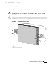
... mounting backboard. Chapter 2 Switch Installation (24- Statement 265 Figure 2-12 Mounting the Switch on a wall with the front panel facing up . Statement 266 Warning If a redundant power system (RPS) is attached securely to wall studs or to the switch, install an RPS connector cover on the back of the switch. Warning To...
... mounting backboard. Chapter 2 Switch Installation (24- Statement 265 Figure 2-12 Mounting the Switch on a wall with the front panel facing up . Statement 266 Warning If a redundant power system (RPS) is attached securely to wall studs or to the switch, install an RPS connector cover on the back of the switch. Warning To...

Hardware Installation Guide
Page 98
...the Network Assistant to configure and manage the switch. POST lasts approximately 1 minute. POST failures are connecting the switch to a Cisco redundant power system (RPS), refer to the documentation that the switch functions properly. You need to complete the setup program, which runs ...to press Enter to display the setup program prompt. Connect the other LEDs remain solid green. Call Cisco technical support representative if your RPS. Connecting to a Power Source Appendix C Configuring the Switch with the CLI-Based Setup Program Step 3 Configure the baud ...
...the Network Assistant to configure and manage the switch. POST lasts approximately 1 minute. POST failures are connecting the switch to a Cisco redundant power system (RPS), refer to the documentation that the switch functions properly. You need to complete the setup program, which runs ...to press Enter to display the setup program prompt. Connect the other LEDs remain solid green. Call Cisco technical support representative if your RPS. Connecting to a Power Source Appendix C Configuring the Switch with the CLI-Based Setup Program Step 3 Configure the baud ...
Hardware Installation Guide
Page 106
...-mounting 2-7 to 2-10, 3-15 to 3-16 rack-mounting warning 2-3, 2-6, 3-2, 3-15 read the wall-mounting instructions warning 2-2, 3-11, 3-17 rear panel clearance 2-5, 3-4 description 1-19 to 1-21 redundant power supply See RPS removing SFP modules 2-17 to 2-18 restricted access area warning 2-3 RJ-45 connector, console port B-4 RJ-45 console port 1-19 RPS attachment...
...-mounting 2-7 to 2-10, 3-15 to 3-16 rack-mounting warning 2-3, 2-6, 3-2, 3-15 read the wall-mounting instructions warning 2-2, 3-11, 3-17 rear panel clearance 2-5, 3-4 description 1-19 to 1-21 redundant power supply See RPS removing SFP modules 2-17 to 2-18 restricted access area warning 2-3 RJ-45 connector, console port B-4 RJ-45 console port 1-19 RPS attachment...


