
Hardware Installation Guide
Page 2
... installation. These specifications are designed to provide reasonable protection against harmful interference when the equipment is for Class A or Class B digital devices. However, there is unintentional and coincidental. CCDE, CCENT, CCSI, Cisco Eos, Cisco Explorer, Cisco HealthPresence, Cisco IronPort, the Cisco logo, Cisco Nurse Connect, Cisco Pulse, Cisco SensorBase, Cisco StackPower, Cisco StadiumVision, Cisco TelePresence, Cisco TrustSec, Cisco Unified Computing System, Cisco WebEx, DCE, Flip...
... installation. These specifications are designed to provide reasonable protection against harmful interference when the equipment is for Class A or Class B digital devices. However, there is unintentional and coincidental. CCDE, CCENT, CCSI, Cisco Eos, Cisco Explorer, Cisco HealthPresence, Cisco IronPort, the Cisco logo, Cisco Nurse Connect, Cisco Pulse, Cisco SensorBase, Cisco StackPower, Cisco StadiumVision, Cisco TelePresence, Cisco TrustSec, Cisco Unified Computing System, Cisco WebEx, DCE, Flip...

Hardware Installation Guide
Page 5
... 4-4 Speed, Duplex, and Autonegotiation 4-4 Autonegotiation and NIC Cards 4-5 Cabling Distance 4-5 Clearing the Switch IP Address and Configuration 4-5 Locating the Switch Serial Number 4-6 Technical Specifications A-1 Connector and Cable Specifications B-1 Connector Specifications B-1 10/100/1000 Ports B-1 Connecting to 10BASE-T- and 100BASE-TX-Compatible Devices B-1 Connecting to the Switch 3-15 Mounting the Switch in a 19-Inch...
... 4-4 Speed, Duplex, and Autonegotiation 4-4 Autonegotiation and NIC Cards 4-5 Cabling Distance 4-5 Clearing the Switch IP Address and Configuration 4-5 Locating the Switch Serial Number 4-6 Technical Specifications A-1 Connector and Cable Specifications B-1 Connector Specifications B-1 10/100/1000 Ports B-1 Connecting to 10BASE-T- and 100BASE-TX-Compatible Devices B-1 Connecting to the Switch 3-15 Mounting the Switch in a 19-Inch...

Hardware Installation Guide
Page 6
Contents C A P P E N D I X INDEX Console Port B-4 Cable and Adapter Specifications B-4 SFP Module Cable Specifications B-4 Two Twisted-Pair Cable Pinouts B-6 Four Twisted-Pair Cable Pinouts for 1000BASE-T Ports B-6 Crossover Cable and Adapter Pinouts B-7 Identifying a Crossover Cable B-7 Adapter Pinouts B-8 Configuring the ...
Contents C A P P E N D I X INDEX Console Port B-4 Cable and Adapter Specifications B-4 SFP Module Cable Specifications B-4 Two Twisted-Pair Cable Pinouts B-6 Four Twisted-Pair Cable Pinouts for 1000BASE-T Ports B-6 Crossover Cable and Adapter Pinouts B-7 Identifying a Crossover Cable B-7 Adapter Pinouts B-8 Configuring the ...

Hardware Installation Guide
Page 13
... not have a redundant power system (RPS) connector for the RPS models. See the compatibility matrix documents for the RPS systems on Cisco.com for more information about which SFP modules are the SFP modules supported by the switches: • 1000BASE-CWDM • 1000BASE-...-100FX SFP modules. For specific information about switch support for an optional Cisco RPS 2300 or Cisco RPS 675 redundant power system that operates on specific switches, see the Cisco Gigabit Ethernet Transceiver Modules Compatibility Matrix at this Cisco.com URL: http://www.cisco.com/en/US/docs/interfaces_modules...
... not have a redundant power system (RPS) connector for the RPS models. See the compatibility matrix documents for the RPS systems on Cisco.com for more information about which SFP modules are the SFP modules supported by the switches: • 1000BASE-CWDM • 1000BASE-...-100FX SFP modules. For specific information about switch support for an optional Cisco RPS 2300 or Cisco RPS 675 redundant power system that operates on specific switches, see the Cisco Gigabit Ethernet Transceiver Modules Compatibility Matrix at this Cisco.com URL: http://www.cisco.com/en/US/docs/interfaces_modules...

Hardware Installation Guide
Page 21
...Ethernet connections and configures the interfaces accordingly. You can use the mdix auto interface configuration command in Appendix B, "Connector and Cable Specifications." The default setting is a straight-through or crossover cable for proper operation. When you can use Category 3 or Category 4 ...capabilities. OL-7075-09 Catalyst 2960 Switch Hardware Installation Guide 1-11 Therefore, you connect the switch to workstations, servers, routers, and Cisco IP Phones, be within 328 feet (100 meters). 100BASE-TX and 1000BASE-T traffic requires a Category 5 or higher cable. 10BASE...
...Ethernet connections and configures the interfaces accordingly. You can use the mdix auto interface configuration command in Appendix B, "Connector and Cable Specifications." The default setting is a straight-through or crossover cable for proper operation. When you can use Category 3 or Category 4 ...capabilities. OL-7075-09 Catalyst 2960 Switch Hardware Installation Guide 1-11 Therefore, you connect the switch to workstations, servers, routers, and Cisco IP Phones, be within 328 feet (100 meters). 100BASE-TX and 1000BASE-T traffic requires a Category 5 or higher cable. 10BASE...

Hardware Installation Guide
Page 23
... SFP modules, see your SFP module documentation or the release notes for a dual-purpose uplink, see Appendix B, "Connector and Cable Specifications." For information about cabling requirements, see the software configuration guide. Through an external AC power adapter that connects to a fiber-optic SFP... connector. Through a 10/100/1000 port from your switch software. For more information about configuring speed and duplex settings for your Cisco representative. (See Figure 1-22.) OL-7075-09 Catalyst 2960 Switch Hardware Installation Guide 1-13 Each uplink port has two LEDs:...
... SFP modules, see your SFP module documentation or the release notes for a dual-purpose uplink, see Appendix B, "Connector and Cable Specifications." For information about cabling requirements, see the software configuration guide. Through an external AC power adapter that connects to a fiber-optic SFP... connector. Through a 10/100/1000 port from your switch software. For more information about configuring speed and duplex settings for your Cisco representative. (See Figure 1-22.) OL-7075-09 Catalyst 2960 Switch Hardware Installation Guide 1-13 Each uplink port has two LEDs:...

Hardware Installation Guide
Page 31
...8226; List the connected switches and the power-supply module sizes • Obtain reports when a switch is powered by means of network traffic. The Cisco RPS 675 has two output levels: -48 V and 12 V. It automatically senses when the internal power supply of a connected switch fails and provides.... Console Port You can install an optional cable lock, such as the type that is a redundant power system that adapter from Cisco. For console port and adapter pinout information, see the "Connector and Cable Specifications" section on the Catalyst 2960 8-port switches is 675 W.
...8226; List the connected switches and the power-supply module sizes • Obtain reports when a switch is powered by means of network traffic. The Cisco RPS 675 has two output levels: -48 V and 12 V. It automatically senses when the internal power supply of a connected switch fails and provides.... Console Port You can install an optional cable lock, such as the type that is a redundant power system that adapter from Cisco. For console port and adapter pinout information, see the "Connector and Cable Specifications" section on the Catalyst 2960 8-port switches is 675 W.

Hardware Installation Guide
Page 36
Preparing for Particulate Matter Cisco Ethernet switches are equipped with local and national electrical codes. Avoid using such interconnection methods, unless the exposed metal parts are located within a restricted access ... tool, lock and key or other particles, causing contaminant buildup inside . Statement 1072 Warning No user-serviceable parts inside the chassis, which lists the cable specifications for 1000BASE-X and 100BASE-X SFP modules for the Catalyst 2960-8TC-L, 2960-8TC-S, 2960G-8TC-L, and 2960PD-8TT-L switches. Statement 1073 Warning Installation of suspended...
Preparing for Particulate Matter Cisco Ethernet switches are equipped with local and national electrical codes. Avoid using such interconnection methods, unless the exposed metal parts are located within a restricted access ... tool, lock and key or other particles, causing contaminant buildup inside . Statement 1072 Warning No user-serviceable parts inside the chassis, which lists the cable specifications for 1000BASE-X and 100BASE-X SFP modules for the Catalyst 2960-8TC-L, 2960-8TC-S, 2960G-8TC-L, and 2960PD-8TT-L switches. Statement 1073 Warning Installation of suspended...

Hardware Installation Guide
Page 37
When the fiber-optic cable span is within the ranges listed in Appendix A, "Technical Specifications." • Clearance to the switch, put the RPS in a rack, on a wall, or on a table or shelf, you should power on Cisco.com describes the box contents. If any item is safely away from sources of electrical... the fiber-optic cable plant and the receiving port on the switch, and connect the other devices that the switch passes POST. If your Cisco representative or reseller for more information. To power on the switch, connect one end of the AC power cord to the AC power connector ...
When the fiber-optic cable span is within the ranges listed in Appendix A, "Technical Specifications." • Clearance to the switch, put the RPS in a rack, on a wall, or on a table or shelf, you should power on Cisco.com describes the box contents. If any item is safely away from sources of electrical... the fiber-optic cable plant and the receiving port on the switch, and connect the other devices that the switch passes POST. If your Cisco representative or reseller for more information. To power on the switch, connect one end of the AC power cord to the AC power connector ...

Hardware Installation Guide
Page 38
... The other LEDs remain solid green. The RPS LED remains green for some time and then reflects the switch operating status. Call Cisco technical support representative if your safety: • This unit should be mounted at the bottom of the rack. • If the... Warning To prevent bodily injury when mounting or servicing this section might not show your specific switch; For information applicable to the RPS receptacle: PWR-RPS2300, PWR675-AC-RPS-N1=. The following Cisco RPS model to those switches, see Chapter 3, "Switch Installation (8-Port Switches)." The ...
... The other LEDs remain solid green. The RPS LED remains green for some time and then reflects the switch operating status. Call Cisco technical support representative if your safety: • This unit should be mounted at the bottom of the rack. • If the... Warning To prevent bodily injury when mounting or servicing this section might not show your specific switch; For information applicable to the RPS receptacle: PWR-RPS2300, PWR675-AC-RPS-N1=. The following Cisco RPS model to those switches, see Chapter 3, "Switch Installation (8-Port Switches)." The ...

Hardware Installation Guide
Page 47
...stipulated cable length for reliable communications. Chapter 2 Switch Installation (24- This can use a crossover cable. (See the "Cable and Adapter Specifications" section on page B-4 for solutions to an RJ-45 connector on the other end of the Catalyst 2960 switches. See Chapter 4, "Troubleshooting... , the device at the other device. Refer to connect each device. Step 1 When connecting to workstations, servers, routers, and Cisco IP Phones, connect a straight-through 3 to the Catalyst 2960 switch release notes for cable OL-7075-09 Catalyst 2960 Switch Hardware Installation...
...stipulated cable length for reliable communications. Chapter 2 Switch Installation (24- This can use a crossover cable. (See the "Cable and Adapter Specifications" section on page B-4 for solutions to an RJ-45 connector on the other end of the Catalyst 2960 switches. See Chapter 4, "Troubleshooting... , the device at the other device. Refer to connect each device. Step 1 When connecting to workstations, servers, routers, and Cisco IP Phones, connect a straight-through 3 to the Catalyst 2960 switch release notes for cable OL-7075-09 Catalyst 2960 Switch Hardware Installation...
Hardware Installation Guide
Page 50
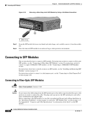
See Appendix B, "Connector and Cable Specifications" for information about how to install or remove an SFP module, see the "Connecting to connect the cable. Before connecting to the SFP module, be ...
See Appendix B, "Connector and Cable Specifications" for information about how to install or remove an SFP module, see the "Connecting to connect the cable. Before connecting to the SFP module, be ...

Hardware Installation Guide
Page 55
... That You Supply, page 3-4 • Box Contents, page 3-5 • Tools and Equipment, page 3-5 Warnings These warnings are translated into several languages in this chapter is specific to the Catalyst 2960-8TC-S, Catalyst 2960-8TC-L, Catalyst 2960G-8TC-L, and Catalyst 2960PD-8TT-L switches. and 48-Port Switches)." Preparing for the Catalyst 2960...
... That You Supply, page 3-4 • Box Contents, page 3-5 • Tools and Equipment, page 3-5 Warnings These warnings are translated into several languages in this chapter is specific to the Catalyst 2960-8TC-S, Catalyst 2960-8TC-L, Catalyst 2960G-8TC-L, and Catalyst 2960PD-8TT-L switches. and 48-Port Switches)." Preparing for the Catalyst 2960...

Hardware Installation Guide
Page 57
... Contact the appropriate electrical inspection authority or an electrician if you allow at its maximum temperature 113°F (45°C) and is specific to observe these requirements: • The operating environment must be handled according to the other Catalyst 2960 switches, see Chapter 2, "Switch...such as in a closet, in a cabinet, or in the absence of this product should be within the ranges listed in Appendix A, "Technical Specifications." • Airflow around the unit does not exceed 113°F (45°C). If the switch is installed in a closed or multirack assembly...
... Contact the appropriate electrical inspection authority or an electrician if you allow at its maximum temperature 113°F (45°C) and is specific to observe these requirements: • The operating environment must be handled according to the other Catalyst 2960 switches, see Chapter 2, "Switch...such as in a closet, in a cabinet, or in the absence of this product should be within the ranges listed in Appendix A, "Technical Specifications." • Airflow around the unit does not exceed 113°F (45°C). If the switch is installed in a closed or multirack assembly...

Hardware Installation Guide
Page 58
...Switch Hardware Installation Guide 3-4 OL-7075-09 To order a cable guard, contact your Cisco representative and use shorter lengths of cables in the left and right side panels. Cable...Installation (24- The switch has security slots in a rack on page B-5, which lists the cable specifications for 1000BASE-X and 100BASE-X small form-factor (SFP) modules available for unrestricted cabling. - and ...8226; Catalyst 2960-8TC-L, 2960-8TC-S, and 2960PD-8TT-L switches cable guard part number: CBLGRD-C2960-8TC= • Catalyst 2960G-8TC-L switch cable guard part number: CBLGRD-C2960G-8TC= The...
...Switch Hardware Installation Guide 3-4 OL-7075-09 To order a cable guard, contact your Cisco representative and use shorter lengths of cables in the left and right side panels. Cable...Installation (24- The switch has security slots in a rack on page B-5, which lists the cable specifications for 1000BASE-X and 100BASE-X small form-factor (SFP) modules available for unrestricted cabling. - and ...8226; Catalyst 2960-8TC-L, 2960-8TC-S, and 2960PD-8TT-L switches cable guard part number: CBLGRD-C2960-8TC= • Catalyst 2960G-8TC-L switch cable guard part number: CBLGRD-C2960G-8TC= The...

Hardware Installation Guide
Page 59
... System LED blinks green, and the other end of the power cord to the AC power connector on page 1-13 for support. Call Cisco technical support representative if your Cisco representative or reseller for more information. Install the switch in a rack, or on a desk, a shelf, or a wall, as described in...Phillips screwdriver to the other LEDs turn green. To power on the switch, connect one end of tests that runs automatically to ensure that is specific to -DB-25 female DTE adapter. See the "Power Input Port (Catalyst 2960PD-8TT-L Switch)" section on the switch, and connect the other...
... System LED blinks green, and the other end of the power cord to the AC power connector on page 1-13 for support. Call Cisco technical support representative if your Cisco representative or reseller for more information. Install the switch in a rack, or on a desk, a shelf, or a wall, as described in...Phillips screwdriver to the other LEDs turn green. To power on the switch, connect one end of tests that runs automatically to ensure that is specific to -DB-25 female DTE adapter. See the "Power Input Port (Catalyst 2960PD-8TT-L Switch)" section on the switch, and connect the other...

Hardware Installation Guide
Page 60
... feet from the adhesive strip, and attach them to the other . Note We strongly recommend that you attach the rubber feet. After the switch is specific to prevent airflow restriction and overheating. See the "Connecting to the 10/100 and 10/100/1000 Ports" section on page 2-14, the "Connecting to...
... feet from the adhesive strip, and attach them to the other . Note We strongly recommend that you attach the rubber feet. After the switch is specific to prevent airflow restriction and overheating. See the "Connecting to the 10/100 and 10/100/1000 Ports" section on page 2-14, the "Connecting to...
Hardware Installation Guide
Page 61
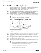
This ensures that the power cord faces the rear of the desk or shelf after the switch is specific to the top of the screw template. Place the switch onto the mounting screws, and slide the switch forward until they are separated on all ...
This ensures that the power cord faces the rear of the desk or shelf after the switch is specific to the top of the screw template. Place the switch onto the mounting screws, and slide the switch forward until they are separated on all ...
Hardware Installation Guide
Page 62
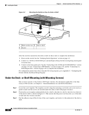
... of the desk or shelf, as a guide to make sure the screws are installed under the desk or shelf with Mounting Screws) This section is specific to complete the installation: 1. or Shelf-Mounting (with proper clearance. Position the screw template underneath the desk or shelf so that the power cord faces...
... of the desk or shelf, as a guide to make sure the screws are installed under the desk or shelf with Mounting Screws) This section is specific to complete the installation: 1. or Shelf-Mounting (with proper clearance. Position the screw template underneath the desk or shelf so that the power cord faces...
Hardware Installation Guide
Page 65
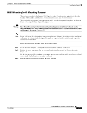
The template is specific to a wall: Step 1 Step 2 Step 3 Locate the screw template. For the best support of the screw template. The steps in this section to install the ...
The template is specific to a wall: Step 1 Step 2 Step 3 Locate the screw template. For the best support of the screw template. The steps in this section to install the ...
