
Hardware Installation Guide
Page 2
...ARE PROVIDED "AS IS" WITH ALL FAULTS. CCDE, CCENT, CCSI, Cisco Eos, Cisco Explorer, Cisco HealthPresence, Cisco IronPort, the Cisco logo, Cisco Nurse Connect, Cisco Pulse, Cisco SensorBase, Cisco StackPower, Cisco StadiumVision, Cisco TelePresence, Cisco TrustSec, Cisco Unified Computing System, Cisco WebEx, DCE, Flip Channels, Flip for Good, Flip Mino, Flipshare ...USE OR INABILITY TO USE THIS MANUAL, EVEN IF CISCO OR ITS SUPPLIERS HAVE BEEN ADVISED OF THE POSSIBILITY OF SUCH DAMAGES. Operation of the FCC rules. THE SPECIFICATIONS AND INFORMATION REGARDING THE PRODUCTS IN THIS MANUAL ARE ...
...ARE PROVIDED "AS IS" WITH ALL FAULTS. CCDE, CCENT, CCSI, Cisco Eos, Cisco Explorer, Cisco HealthPresence, Cisco IronPort, the Cisco logo, Cisco Nurse Connect, Cisco Pulse, Cisco SensorBase, Cisco StackPower, Cisco StadiumVision, Cisco TelePresence, Cisco TrustSec, Cisco Unified Computing System, Cisco WebEx, DCE, Flip Channels, Flip for Good, Flip Mino, Flipshare ...USE OR INABILITY TO USE THIS MANUAL, EVEN IF CISCO OR ITS SUPPLIERS HAVE BEEN ADVISED OF THE POSSIBILITY OF SUCH DAMAGES. Operation of the FCC rules. THE SPECIFICATIONS AND INFORMATION REGARDING THE PRODUCTS IN THIS MANUAL ARE ...

Hardware Installation Guide
Page 5
... Switch Performance 4-4 Speed, Duplex, and Autonegotiation 4-4 Autonegotiation and NIC Cards 4-5 Cabling Distance 4-5 Clearing the Switch IP Address and Configuration 4-5 Locating the Switch Serial Number 4-6 Technical Specifications A-1 Connector and Cable Specifications B-1 Connector Specifications B-1 10/100/1000 Ports B-1 Connecting to 1000BASE-T Devices B-2 SFP Module Ports B-3 Dual-Purpose Ports B-3 Catalyst 2960 Switch Hardware Installation Guide v
... Switch Performance 4-4 Speed, Duplex, and Autonegotiation 4-4 Autonegotiation and NIC Cards 4-5 Cabling Distance 4-5 Clearing the Switch IP Address and Configuration 4-5 Locating the Switch Serial Number 4-6 Technical Specifications A-1 Connector and Cable Specifications B-1 Connector Specifications B-1 10/100/1000 Ports B-1 Connecting to 1000BASE-T Devices B-2 SFP Module Ports B-3 Dual-Purpose Ports B-3 Catalyst 2960 Switch Hardware Installation Guide v

Hardware Installation Guide
Page 6
Contents C A P P E N D I X INDEX Console Port B-4 Cable and Adapter Specifications B-4 SFP Module Cable Specifications B-4 Two Twisted-Pair Cable Pinouts B-6 Four Twisted-Pair Cable Pinouts for 1000BASE-T Ports B-6 Crossover Cable and Adapter Pinouts B-7 Identifying a Crossover Cable B-7 Adapter Pinouts B-8 Configuring the ...
Contents C A P P E N D I X INDEX Console Port B-4 Cable and Adapter Specifications B-4 SFP Module Cable Specifications B-4 Two Twisted-Pair Cable Pinouts B-6 Four Twisted-Pair Cable Pinouts for 1000BASE-T Ports B-6 Crossover Cable and Adapter Pinouts B-7 Identifying a Crossover Cable B-7 Adapter Pinouts B-8 Configuring the ...

Hardware Installation Guide
Page 13
... and 10/100/1000 ports autonegotiate speed and support full-duplex or half-duplex mode. For specific information about switch support for an optional Cisco RPS 2300 or Cisco RPS 675 redundant power system that operates on AC input and supplies backup DC power to the... switch. Chapter 1 Product Overview Features These are supported on specific switches, see the Cisco Gigabit Ethernet Transceiver Modules Compatibility Matrix at this Cisco.com URL: http://www.cisco.com/en/US/docs/interfaces_modules/transceiver_modules/compatibility/matrix/ OL_6981.html The 1000BASE-T SFP ...
... and 10/100/1000 ports autonegotiate speed and support full-duplex or half-duplex mode. For specific information about switch support for an optional Cisco RPS 2300 or Cisco RPS 675 redundant power system that operates on AC input and supplies backup DC power to the... switch. Chapter 1 Product Overview Features These are supported on specific switches, see the Cisco Gigabit Ethernet Transceiver Modules Compatibility Matrix at this Cisco.com URL: http://www.cisco.com/en/US/docs/interfaces_modules/transceiver_modules/compatibility/matrix/ OL_6981.html The 1000BASE-T SFP ...

Hardware Installation Guide
Page 21
...TX traffic requires a Category 5 or higher cable. 10BASE-T traffic can use the mdix auto interface configuration command in Appendix B, "Connector and Cable Specifications." In all cases, the attached device must be within 328 feet (100 meters). 100BASE-TX and 1000BASE-T traffic requires a Category 5 or ...switch port negotiates the best connection (that the cable is autonegotiate. When you connect the switch to workstations, servers, routers, and Cisco IP Phones, be sure to use the mdix auto interface configuration command in full-duplex or half-duplex mode. Pinouts for proper ...
...TX traffic requires a Category 5 or higher cable. 10BASE-T traffic can use the mdix auto interface configuration command in Appendix B, "Connector and Cable Specifications." In all cases, the attached device must be within 328 feet (100 meters). 100BASE-TX and 1000BASE-T traffic requires a Category 5 or ...switch port negotiates the best connection (that the cable is autonegotiate. When you connect the switch to workstations, servers, routers, and Cisco IP Phones, be sure to use the mdix auto interface configuration command in full-duplex or half-duplex mode. Pinouts for proper ...

Hardware Installation Guide
Page 23
...media-type interface configuration command to a fiber-optic SFP module. For information about cabling requirements, see Appendix B, "Connector and Cable Specifications." Chapter 1 Product Overview Front Panel Description SFP Module Slots The Catalyst 2960 switches (other switches. You can use Gigabit Ethernet SFP... modules for Gigabit uplink connections and 100-Megabit SFP modules for your Cisco representative. (See Figure 1-22.) OL-7075-09 Catalyst 2960 Switch Hardware Installation Guide 1-13 However, you insert an SFP ...
...media-type interface configuration command to a fiber-optic SFP module. For information about cabling requirements, see Appendix B, "Connector and Cable Specifications." Chapter 1 Product Overview Front Panel Description SFP Module Slots The Catalyst 2960 switches (other switches. You can use Gigabit Ethernet SFP... modules for Gigabit uplink connections and 100-Megabit SFP modules for your Cisco representative. (See Figure 1-22.) OL-7075-09 Catalyst 2960 Switch Hardware Installation Guide 1-13 However, you insert an SFP ...

Hardware Installation Guide
Page 31
...the RPS • Obtain status reports for the RPS power-supply module • Read and monitor backup, failure, and exception history Cisco RPS 675 The Cisco 675 RPS is a redundant power system that supports six network devices and provides power to the failed switch, preventing loss of network ...8226; Obtain reports when a switch is powered by means of the switch. For console port and adapter pinout information, see the "Connector and Cable Specifications" section on the left -side panel. You can order a kit (part number ACS-DSBUASYN=) containing that is used to secure a laptop computer...
...the RPS • Obtain status reports for the RPS power-supply module • Read and monitor backup, failure, and exception history Cisco RPS 675 The Cisco 675 RPS is a redundant power system that supports six network devices and provides power to the failed switch, preventing loss of network ...8226; Obtain reports when a switch is powered by means of the switch. For console port and adapter pinout information, see the "Connector and Cable Specifications" section on the left -side panel. You can order a kit (part number ACS-DSBUASYN=) containing that is used to secure a laptop computer...

Hardware Installation Guide
Page 36
... replacing the unit, the ground connection must be no longer than 328 feet (100 meters). • The cables meet the specifications in Table B-1 on Power over Ethernet (PoE) circuits if interconnections are made first and disconnected last. These standards provide guidelines ...Installation (8-Port Switches)." Statement 1072 Warning No user-serviceable parts inside the chassis, which lists the cable specifications for 1000BASE-X and 100BASE-X SFP modules for Particulate Matter Cisco Ethernet switches are made aware of security. When you determine where to place the switch, be sure...
... replacing the unit, the ground connection must be no longer than 328 feet (100 meters). • The cables meet the specifications in Table B-1 on Power over Ethernet (PoE) circuits if interconnections are made first and disconnected last. These standards provide guidelines ...Installation (8-Port Switches)." Statement 1072 Warning No user-serviceable parts inside the chassis, which lists the cable specifications for 1000BASE-X and 100BASE-X SFP modules for Particulate Matter Cisco Ethernet switches are made aware of security. When you determine where to place the switch, be sure...

Hardware Installation Guide
Page 37
... front and rear panels meets these conditions: - See Chapter 3, "Switch Installation (8-Port Switches)," and see the Cisco RPS documentation for unrestricted cabling. - If your Cisco representative or reseller for support. Note When you should insert a 5-decibel (dB) or 10-dB inline optical ...When you use shorter lengths of single-mode fiber cable, you should power on Cisco.com describes the box contents. When the fiber-optic cable span is installed in Appendix A, "Technical Specifications." • Clearance to rack-mount the switch. Chapter 2 Switch Installation (24...
... front and rear panels meets these conditions: - See Chapter 3, "Switch Installation (8-Port Switches)," and see the Cisco RPS documentation for unrestricted cabling. - If your Cisco representative or reseller for support. Note When you should insert a 5-decibel (dB) or 10-dB inline optical ...When you use shorter lengths of single-mode fiber cable, you should power on Cisco.com describes the box contents. When the fiber-optic cable span is installed in Appendix A, "Technical Specifications." • Clearance to rack-mount the switch. Chapter 2 Switch Installation (24...

Hardware Installation Guide
Page 38
...the system remains stable. Statement 1006 Catalyst 2960 Switch Hardware Installation Guide 2-6 OL-7075-09 and 48-port switches. The following Cisco RPS model to ensure that the switch functions properly. LEDs can blink during the test. When the switch begins POST, the System...switch operating status. The RPS LED remains green for some time and then reflects the switch operating status. Call Cisco technical support representative if your specific switch; For information applicable to all switches except the Catalyst 8-port switches. and 48-Port Switches) Warning ...
...the system remains stable. Statement 1006 Catalyst 2960 Switch Hardware Installation Guide 2-6 OL-7075-09 and 48-port switches. The following Cisco RPS model to ensure that the switch functions properly. LEDs can blink during the test. When the switch begins POST, the System...switch operating status. The RPS LED remains green for some time and then reflects the switch operating status. Call Cisco technical support representative if your specific switch; For information applicable to all switches except the Catalyst 8-port switches. and 48-Port Switches) Warning ...

Hardware Installation Guide
Page 47
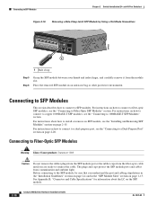
...and laser receive (RX). Each SFP module must not exceed the stipulated cable length for reliable communications. See the "SFP Module Cable Specifications" section on when both the switch and the connected device have established link. For configuration information for the list of the same type ...2960 Switch Hardware Installation Guide 2-15 You can take up to connect each device. Step 1 When connecting to workstations, servers, routers, and Cisco IP Phones, connect a straight-through 3 to 30 seconds, and then the port LED turns green. Installing and Removing SFP Modules SFP ...
...and laser receive (RX). Each SFP module must not exceed the stipulated cable length for reliable communications. See the "SFP Module Cable Specifications" section on when both the switch and the connected device have established link. For configuration information for the list of the same type ...2960 Switch Hardware Installation Guide 2-15 You can take up to connect each device. Step 1 When connecting to workstations, servers, routers, and Cisco IP Phones, connect a straight-through 3 to 30 seconds, and then the port LED turns green. Installing and Removing SFP Modules SFP ...
Hardware Installation Guide
Page 50
... Hardware Installation Guide OL-7075-09 Place the removed SFP module in the "SFP Module Slots" section on page 2-15. See Appendix B, "Connector and Cable Specifications" for information about how to install or remove an SFP module, see the "Connecting to SFP Modules Chapter 2 Switch Installation (24- The plugs and caps...
... Hardware Installation Guide OL-7075-09 Place the removed SFP module in the "SFP Module Slots" section on page 2-15. See Appendix B, "Connector and Cable Specifications" for information about how to install or remove an SFP module, see the "Connecting to SFP Modules Chapter 2 Switch Installation (24- The plugs and caps...

Hardware Installation Guide
Page 55
... the other Catalyst 2960 switches, see Chapter 2, "Switch Installation (24- Warning To prevent the switch from overheating, do not operate it in this chapter is specific to the switch, see Chapter 2, "Switch Installation (24- Preparing for Installation This section covers these topics: • Warnings, page 3-1 • Installation Guidelines, page 3-3 • Equipment...
... the other Catalyst 2960 switches, see Chapter 2, "Switch Installation (24- Warning To prevent the switch from overheating, do not operate it in this chapter is specific to the switch, see Chapter 2, "Switch Installation (24- Preparing for Installation This section covers these topics: • Warnings, page 3-1 • Installation Guidelines, page 3-3 • Equipment...

Hardware Installation Guide
Page 57
... equipment is installed, the following ports must be connected through the vents must be within the ranges listed in Appendix A, "Technical Specifications." • Airflow around the switch and through an approved network termination unit with local and national electrical codes. Statement 1040. Statement...if the switch is operating at its maximum temperature 113°F (45°C) and is in an environment that suitable grounding is specific to the other Catalyst 2960 switches, see Chapter 2, "Switch Installation (24- Statement 1044 Warning When installing or replacing the unit,...
... equipment is installed, the following ports must be connected through the vents must be within the ranges listed in Appendix A, "Technical Specifications." • Airflow around the switch and through an approved network termination unit with local and national electrical codes. Statement 1040. Statement...if the switch is operating at its maximum temperature 113°F (45°C) and is in an environment that suitable grounding is specific to the other Catalyst 2960 switches, see Chapter 2, "Switch Installation (24- Statement 1044 Warning When installing or replacing the unit,...

Hardware Installation Guide
Page 58
...such as radios, power lines, and fluorescent lighting fixtures. To order a cable guard, contact your Cisco representative and use to manage a large number of cables in the rack. • Do not...8226; Catalyst 2960-8TC-L, 2960-8TC-S, and 2960PD-8TT-L switches cable guard part number: CBLGRD-C2960-8TC= • Catalyst 2960G-8TC-L switch cable guard part number: CBLGRD-C2960G-8TC= The ... attenuator in the link to avoid overloading the receiver. When the fiber-optic cable span is specific to the Catalyst 2960 8-port switches. and 48-Port Switches)." Preparing for Installation Chapter 3 ...
...such as radios, power lines, and fluorescent lighting fixtures. To order a cable guard, contact your Cisco representative and use to manage a large number of cables in the rack. • Do not...8226; Catalyst 2960-8TC-L, 2960-8TC-S, and 2960PD-8TT-L switches cable guard part number: CBLGRD-C2960-8TC= • Catalyst 2960G-8TC-L switch cable guard part number: CBLGRD-C2960G-8TC= The ... attenuator in the link to avoid overloading the receiver. When the fiber-optic cable span is specific to the Catalyst 2960 8-port switches. and 48-Port Switches)." Preparing for Installation Chapter 3 ...

Hardware Installation Guide
Page 59
.... You can power the Catalyst 2960PD-8TT-L switch through a 10/100/1000 uplink port, which can receive power from Cisco. Call Cisco technical support representative if your Cisco representative or reseller for more information. or Shelf-Mounting (without Mounting Screws), page 3-6 • Desk- When the switch...that is not included with Mounting Screws), page 3-7 OL-7075-09 Catalyst 2960 Switch Hardware Installation Guide 3-5 The kit part number is specific to rack-mount the switch. LEDs can order a kit (part number ACS-DSBUASYN=) with that adapter from the switch. You can...
.... You can power the Catalyst 2960PD-8TT-L switch through a 10/100/1000 uplink port, which can receive power from Cisco. Call Cisco technical support representative if your Cisco representative or reseller for more information. or Shelf-Mounting (without Mounting Screws), page 3-6 • Desk- When the switch...that is not included with Mounting Screws), page 3-7 OL-7075-09 Catalyst 2960 Switch Hardware Installation Guide 3-5 The kit part number is specific to rack-mount the switch. LEDs can order a kit (part number ACS-DSBUASYN=) with that adapter from the switch. You can...

Hardware Installation Guide
Page 60
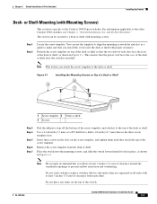
... strongly recommend that you allow at least 3 inches (7.6 cm) of a desk or shelf with the rubber feet in the accessory kit. After the switch is specific to complete the installation: 1. Power on the bottom of the unit. Connect to the front-panel ports. See the switch getting started guide for instructions...
... strongly recommend that you allow at least 3 inches (7.6 cm) of a desk or shelf with the rubber feet in the accessory kit. After the switch is specific to complete the installation: 1. Power on the bottom of the unit. Connect to the front-panel ports. See the switch getting started guide for instructions...
Hardware Installation Guide
Page 61
... power cord faces the rear of the switch. Do not place any items on the top of the desk or shelf after the switch is specific to drill a 1/2-inch (12.7 mm) hole in Figure 3-1. Chapter 3 Switch Installation (8-Port Switches) Installing the Switch Desk-
... power cord faces the rear of the switch. Do not place any items on the top of the desk or shelf after the switch is specific to drill a 1/2-inch (12.7 mm) hole in Figure 3-1. Chapter 3 Switch Installation (8-Port Switches) Installing the Switch Desk-
Hardware Installation Guide
Page 62
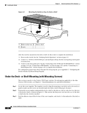
... CLI setup program, go to Appendix C, "Configuring the Switch with Mounting Screws) This section is also used to align the mounting screw holes and is specific to the underside of a Desk or Shelf SYST STAT DPLX SPD MODE CONSOLE 1x 2x 3x 4x 5x 6x 7x 8x Catalyst 296S0eries 1 1 3 204626 2 1 Slides...
... CLI setup program, go to Appendix C, "Configuring the Switch with Mounting Screws) This section is also used to align the mounting screw holes and is specific to the underside of a Desk or Shelf SYST STAT DPLX SPD MODE CONSOLE 1x 2x 3x 4x 5x 6x 7x 8x Catalyst 296S0eries 1 1 3 204626 2 1 Slides...
Hardware Installation Guide
Page 65
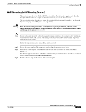
The template is specific to the system. For the best support of the screw template. The steps in this section to install the switch to follow the correct procedures ...
The template is specific to the system. For the best support of the screw template. The steps in this section to install the switch to follow the correct procedures ...
